Table of Contents
Advertisement
Quick Links
Excelsior
Flueless Inset
Fuel Effect Gas Fire
Manual or Remote control
INSTALLATION A A ND U U SER
INSTRUCTIONS
All i i nstructions m m ust b b e h h anded t t o u u ser f f or s s afekeeping
Revision B - 08/04
Country(s) of destination - GB/IE
Focal Point Fires plc, Avon Trading Park, Christchurch, Dorset BH23 2BT
Tel: 01202 499330
Fax: 01202 499326
www.focalpoint.co.uk
e-mail: sales@focalpointfires.co.uk
Advertisement
Table of Contents

Related Manuals for FocalPoint Excelsior


Summary of Contents for FocalPoint Excelsior
- Page 1 Excelsior Flueless Inset Fuel Effect Gas Fire Manual or Remote control INSTALLATION A A ND U U SER INSTRUCTIONS All i i nstructions m m ust b b e h h anded t t o u u ser f f or s s afekeeping...
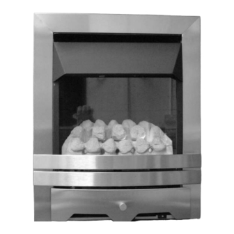
- Page 2 Elegance Blenheim Lulworth Appliance is shown in a variety of styles and finishes...
- Page 3 INST T ALLAT T ION I I NST T RUCT T IONS P P r r e e l l i i m m i i n n a a r r y y N N o o t t e e s s B B e e f f o o r r e e I I n n s s t t a a l l l l a a t t i i o o n n This is a High Efficiency, Flueless, Inset Live Fuel Effect appliance.
-
Page 4: Table Of Contents
Sec c tion Contents s Pag g e N N o. Sec c tion Contents s Pag g e N N o. Important N N otes 8.1 Cable Fixing Appliance D D ata Fuel B B ed Installation R R equirements 10.0 Fitting D D ecorative H H ood/Frame 3.1 Room Sizing... -
Page 5: Appliance D D Ata
APPLIANCE D D ATA Gas Group G20 Natural Gas CAT I2H Inlet Pressure 20 mbar Max Energy Input Gross 2.6 kW 2.35 kW Max Gas Rate 0.25 m3/h Min Energy Input Gross 1.5 kW 1.35 kW Pilot Energy Input Gross 166 W 150 W Setting Pressure... -
Page 6: Ventilation
SITE REQUIREMENTS (continued) Opening DEPTH must be 145 mm or greater. Opening DEPTH includes any plaster, cement or infill/back pan- els that form part of the installation. In the event that the fire is sited in a disused or unserviceable fireplace served by a natural draught flue, any exist- ing under grate draught device should be sealed off to prevent loss of heat or creation of draughts. -
Page 7: Unpacking T T He A A Ppliance
UNPACKING T T HE A A PPLIANCE Stand the carton the right way up, cut the strapping bands and remove the top endcap. Read ALL these instruc- tions before continuing to unpack or install this appliance. Remove the box containing the cast front fret, and the box containing the ceramic coals and other ceramic firebed components. -
Page 8: Installation Method 1
GAS S S UPPLY R R OUTES The gas supply may enter the fire over the hearth or by concealed connection behind the fire. Following preparation of the fixing method, the concealed gas supply (if required), can now be installed. When the opening is ready for installation the gas supply can be routed (examples are shown in the following dia- gram). - Page 9 INSTALLATION M M ETHOD 2 2 ( ( recessing i i nto a a n n on-c c ombustible w w all) This s m m ethod a a llows s f f or i i ns s tallation o o f t t he a a pplianc c e w w ith t t he r r ear p p art r r ec c es s s s ed i i nto t t he i i nner l l eaf o o f a a c c avity w w all. This s s s hould e e nable a a s s tandard f f ire s s urround a a nd b b ac c k p p anel/hearth s s et t t o b b e f f itted t t o t t he w w all w w ith t t he f f ire p p re- s s ented n n aturally i i n a a f f lus s h f f itted m m anner.
- Page 10 INSTALLATION M M ETHOD 3 3 ( ( timber f f ramed b b uildings) Where removal of any part of a timber frame is undertaken the structural integrity of the wall must be retained. The advice of your local building control officer should be sought. If the property is under any NHBC warranty it is also advised that their advice on this kind of modification is sought.
-
Page 11: Installation Method
INSTALLATION METHOD 3 3 ( ( continued) 50mm Rockwool to Insulate Cavity Superlux Box: 12mm thick, External Fireplace Backpanel, Dims; Height 670mm, Width non-combustible 529mm, Depth 207mm Rockwool Insulation 50mm Cavity Box sides and rear 100mm top Inner cavity Leaf Outer Cavity Leaf Ins s tallation a a s s p p er m m ethod 2 2 ( ( rec c es s s s ing g i i nto a a w w all) ) When setting the appliance into the wall find a suitable position between frame timbers and open up the hole. -
Page 12: Cable Fixing
CABLE F F IXING When using this method for fixing, the minimum depth of the open- ing must be increased from 145 mm to 175 mm. This is to allow for the eyebolts and a space for the cable tensioning. 380 mm Drill four holes as shown in the diagram and fit the fibre rawlplugs. -
Page 13: Fitting D D Ecorative H H Ood/Frame
FUEL BED (continued) Fit the glass door assembly with the 4 screws provide in the posi- tions indicated. Ensure that the screws are tightened so as to achieve a good seal between the glass frame gasket and the fire- box. The fire is designed to operate correctly with the supplied com- ponents according to the instructions. -
Page 14: Spark Failure
11.2 OPERATING T T HE F F IRE ( ( remote c c ontrol v v ersions) The gas valve has two control knobs ; Turn the main burner control (shown on left hand side of control valve) knob fully anti-clockwise. Turn ignition knob (shown on right hand side of control valve) slightly left towards the ignition posi- tion until reaching the stop, press down and hold... -
Page 15: Setting Pressure
11.5 SETTING P P RESSURE(continued) The burner pressure should be in accordance with the figures stated in the data section of these instruc- tions. The fire is factory set to achieve these pressures and any significant variation could indicate a supply problem. -
Page 16: Pilot Assembly
13.2 SERVICING T T HE B B URNER T T RAY A A ND G G AS A A SSEMBLY Firstly, remove the hood and front fret, the glass panel and ceramics, and disconnect the gas connection at the isolator elbow. Remove the burner tray by removing the 2 securing screws through the legs. The gas connec- tions to the gas valve can now be released. -
Page 17: Catalytic Converter
13.4 CATALYTIC CONVERTER ( ( continued) Now divide the concentration of carbon monoxide (CO) expressed in percent by the concentration of carbon dioxide (CO2) to obtain the appliance combustion ratio. CO (%) CO2 (%) = ratio The c c ombustion r r atio o o f t t he g g asses e e mitted b b y t t he c c atalytic c c onvertor s s hould n n ot e e xceed 0 0 .0015. If replacing the catalytic converter, remove the hood and front fret, then the glass panel. - Page 18 14.0 TROUBLESHOOTING G G UIDE ( ( continued) Pilot f f lame s s hrinks s w w hen f f ire i i s s o o n h h ig g h Poor gas flow to fire - check pressure with fire on high. If pressure is low - remove any restriction in pipework or valve.
- Page 19 USER I I NSTRUCTIONS Sec c tion Content Pag g e N N o Important Notes Fire Front Clearances to Combustibles Ventilation and Room Size Operating Instructions Combustion Spillage Monitoring System Cleaning Ceramics Servicing 10.0 List of Replacement Parts IMPORTANT N N OTES The installation and Servicing of this fire MUST only be carried out by a competent person (such as a CORGI registered fitter) in accordance with the Gas Safety (Installation and Use) Regulations 1998, the relevant British Standards, Codes of Practice, the Building Regulations and the manufacturer's instructions.
- Page 20 FIREFRONT This fire is supplied with a particular style of fire front. Use of the fire front will ensure an adequate airflow under the firebox for the correct functioning of this appliance. Compliance with safety standards cannot be guaranteed when another style of front is used. CLEARANCES T T O C C OMBUSTIBLES A non-combustible shelf may be fitted to within 100mm of the top edge of the fire frame.
- Page 21 OPERATING T T HE F F IRE ( ( remote c c ontrol v v ersions) The gas valve has two control knobs ; Turn the main burner control (shown on left hand side of control valve) knob fully anti-clockwise. Turn ignition knob (shown on right hand side of control valve) slightly left towards the ignition posi- tion until reaching the stop, press down and hold...
- Page 22 CERAMICS Refer to the relevant section of the Installation section of this booklet for instructions on cleaning and replacing the ceramics. SERVICING The fire should be checked on an annual basis to ensure it is working safely and that there is no excessive build up of soot.
Need help?
Do you have a question about the Excelsior and is the answer not in the manual?
Questions and answers