Table of Contents
Advertisement
Quick Links
INSTALLATION & USER INSTRUCTIONS
Focal Point Fires plc.
Christchurch, Dorset BH23 2BT
Tel: 01202 499330
Fax: 01202 499326
www.focalpointfires.co.uk
e : sales@focalpointfires.co.uk
Questions or problems with your appliance?
Don't take it back to the store
01202 588601
just give us a call on
lines open between 9am and 5pm, Monday to Friday
IN THE UK ALWAYS USE A GAS SAFE REGISTERED ENGINEER TO INSTALL, REPAIR OR SERVICE THIS APPLIANCE
Please note : Except where otherwise stated, all rights,
including copyright in the text, images and layout of this
booklet is owned by Focal Point Fires plc. You are not per-
mitted to copy or adapt any of the content without the
prior written permission of Focal Point Fires plc.
INSET FLUELESS GAS FIRE
MODELS COVERED BY THESE INSTRUCTIONS
PI27 BLENHEIM
PI27 ENVY
P127 HORIZON
P127 LULWORTH
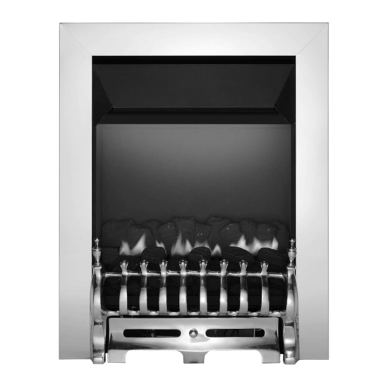
MODEL SHOWN: BLENHEIM INSET FLUELESS
we're here to help
The products covered by this booklet are protected under
patent GB2275331C.
All instructions must be handed to the user for
Revision G - 02/13
1
BS EN 14829 : 2007
safekeeping.
©
2013 Focal Point Fires plc.
GB IE
KM579167
Advertisement
Table of Contents

Related Manuals for FocalPoint PI27 BLENHEIM


Summary of Contents for FocalPoint PI27 BLENHEIM
- Page 1 INSTALLATION & USER INSTRUCTIONS INSET FLUELESS GAS FIRE GB IE MODELS COVERED BY THESE INSTRUCTIONS PI27 BLENHEIM PI27 ENVY Focal Point Fires plc. P127 HORIZON Christchurch, Dorset BH23 2BT P127 LULWORTH Tel: 01202 499330 Fax: 01202 499326 www.focalpointfires.co.uk e : sales@focalpointfires.co.uk...
-
Page 2: Table Of Contents
I N S T A L L A T I O N I N S T R U C T I O N S GB IE Section Contents Page No. Section Contents Page No. Important Notes 7.1 Cable Fixing Appliance Data 7.2 Checking the Burner &... -
Page 3: Appliance Data
2.0 APPLIANCE DATA GB IE Operating/Inlet Pressure Max Energy Input (kW) Min Energy Input (kW) Destination (±2.0 mbar) Model Country Gross Gross I 2H PI27 - Natural Gas GB - IE 1.15 Please see Data Badge affixed to appliance for current data. This appliance is for use only with the gas type, and at the pressure stated on the appliance Data Badge. - Page 4 4.0 SITE REQUIREMENTS GB IE - CONTINUED Dimension: Blenheim & Euphoria models Envy models ‘a’ minimum ‘b’ ‘a’ maximum ‘b’ minimum ‘b’ maximum ‘c’ minimum ‘c’ maximum None None ‘a’ ‘d’ minimum ‘e’ minimum ‘c’ ‘f ’ minimum ‘g’ minimum ‘g’...
-
Page 5: Ventilation
4.0 SITE REQUIREMENTS - GB IE CONTINUED Clearances to the sides of the appliance are 100mm (4”). Clearance to the front of the appliance is 500mm (20”). The sides and back of the appliance may be installed directly onto a non-combustible surfaces. A non combustible shelf of any depth may be positioned above the appliance provided it is no closer than 200 mm from the top of the appliance glass panel and the wall above the appliance is non combustible. -
Page 6: Appliance Installation
6.0 APPLIANCE INSTALLATION GB IE Note: Ensure that the gas supply is isolated before commencing installation of the appliance. The fireplace opening and environment must be in compliance with specifications laid down in the appropriate sections of these instructions. 6.1 PREPARING THE APPLIANCE Remove the appliance from its carton as described previously and stand on a dustsheet. - Page 7 6.4 INSTALLATION METHOD 2 GB IE (recessing into a non-combustible wall) This method allows for installation of the appliance with the rear of the firebox recessed into the inner leaf of a cavity wall.This should enable a standard fire surround and back panel/hearth set to be fitted to the wall with the fire presented naturally in a flush fitted manner.The structural integrity of the wall must be maintained.
-
Page 8: Installation Method
6.5 INSTALLATION METHOD 3 GB IE (timber framed buildings) Where removal of any part of a timber frame is undertaken the structural integrity of the wall must be retained. The advice of your local building control officer should be sought. If the property is under any NHBC warranty it is also advised that their advice on this kind of modification is sought. -
Page 9: Installation Method
6.6 INSTALLATION METHOD 4 GB IE This method allows for a ‘hole in the wall’ installation of the appliance with the rear part recessed into the inner leaf of a cavity wall.The structural integrity of the wall must be maintained.The wall must be non-combustible. Figure 10 All dimensions in mm Figure 11... -
Page 10: Checking The Burner & Spark Gap
7.2 CHECKING THE BURNER AND SPARK GAP GB IE Envy models only : There are no imitation fuel bed components to install. The appli- ance features a ribbon burner which is designed to produce a continuous band of flame Figure 13 over it’s length. -
Page 11: Fitting Decorative Hood/Frame
7.4 FITTING THE DECORATIVE FRAME AND HOOD GB IE Figure 17 The appliance is supplied with a decorative frame and hood. Attach the hoo d using two M6 screws as shown in figure 17. Blenheim & Horizon models : Remove all protective film from the frame. -
Page 12: Briefing The Customer
8.3 BRIEFING THE CUSTOMER GB IE All instructions must be handed to the user for safekeeping. Show the customer how to light and control the fire. After commissioning the appliance, the customer should be instructed on the safe use of the appliance and the need for regular servicing. -
Page 13: Pilot Assembly
9.3 PILOT ASSEMBLY GB IE Clean the pilot assembly with a soft brush and blow through. Check the aeration holes are free of any dirt or lint. Clean thoroughly internally, the connection can be removed from the base of the pilot unit using two spanners to make cleaning easier. -
Page 14: Troubleshooting Guide
10.0 TROUBLESHOOTING GUIDE GB IE • No gas to fire, check isolators are open and gas supply is on. Fire sparks but pilot does not light • Pipework blockage, clean out. • Air not fully purged, re purge supply or wait longer. •... - Page 15 U S E R I N S T R U C T I O N S GB IE Section Contents Page No Important Notes Fire Front Clearances Ventilation and Room Size Fire Guards Operating Instructions Combustion Monitoring System Fitting the Fuel Bed (Blenheim & Horizon) Cleaning 10.0 Servicing...
- Page 16 3.0 CLEARANCES GB IE Clearances to non-combustibles Non combustible surfaces are defined as brick, metal, marble, concrete etc. and also a number of man-made materials impervious to flame. If in doubt refer to the material manufacturer for further information before proceeding with installation. The wall/back panel for the opening must always be non-combustible.
-
Page 17: Figure
5.0 FIRE GUARDS GB IE The fireguards specified in BS 8423 are intended to protect people from falling into a fire, prevent burns and reduce the risk of injury, particularly to young children and the infirm. In addition it is intended to reduce the risk of fire resulting from clothing and/or other flammable materials coming into contact with, or in proximity to, burning fuel and/or hot surfaces. - Page 18 8.0 FITTING THE FUEL BED (Blenheim & Horizon models) GB IE Figure 4 The appliance features a coal style fuel effect. 1. Place the rear coal strip onto the shelf behind the burner as shown in figure 4. Ensure that the four protruding screw heads engage the hollow areas on the underside of the piece.
-
Page 19: Service History
12.0 INSTALLATION DETAILS GB IE Name & contact details of installer : Supplied by : Installer GAS SAFE registration No : Model : Fire serial No. : Date installed : 13.0 SERVICE HISTORY Date of service Serviced by (name): GAS SAFE No. : Contact details of Engineer 14.0 GUARANTEE - TERMS AND CONDITIONS The 3 year guarantee only covers products purchased on or after 1st February 2009.
Need help?
Do you have a question about the PI27 BLENHEIM and is the answer not in the manual?
Questions and answers