Table of Contents
Advertisement
INSTALLATION & USER INSTRUCTIONS
Focal Point Fires plc.
Christchurch, Dorset BH23 2BT
Tel: 01202 499330
Fax: 01202 499326
www.focalpointfires.co.uk
e : sales@focalpointfires.co.uk
Questions or problems with your appliance?
Don't take it back to the store
01202 588601
just give us a call on
lines open between 9am and 5pm, Monday to Friday
IN THE UK ALWAYS USE A GAS SAFE REGISTERED ENGINEER TO INSTALL, REPAIR OR SERVICE THIS APPLIANCE
Please note : Except where otherwise stated, all rights, including
copyright in the text, images and layout of this booklet is owned by
Focal Point Fires plc. You are not permitted to copy or adapt any of
the content without the prior written permission of Focal Point Fires
plc.
MULTIFLUE/INSET GAS FIRE
MODELS COVERED BY THESE INSTRUCTIONS
BLENHEIM MULTIFLUE
LULWORTH MULTIFLUE
EXCELSIOR MULTIFLUE
VOGUE
*
AURA MULTIFLUE
FINSBURY MULTIFLUE
SOHO MULTIFLUE
BI-FLAME
*
HORIZON MULIFLUE
LANGHAM MULTIFLUE
* AVAILABLE WITH MANUAL CONTROL ONLY
† AVAILABLE WITH MANUAL OR SLIDE CONTROL
† † AVAILABLE WITH MANUAL OR REMOTE CONTROL
** AVAILABLE WITH MANUAL, SLIDE CONTROL OR REMOTE CONTROL
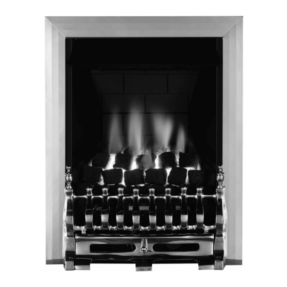
MODEL SHOWN: BLENHEIM MULTIFLUE
we're here to help
**
† †
*
*
**
†
† †
† †
All instructions must be handed to the user for
1
safekeeping.
Revision F - 06/14
© 2014 Focal Point Fires plc.
GB IE
Advertisement
Chapters
Table of Contents


Need help?
Do you have a question about the Blenheim Multiflue and is the answer not in the manual?
Questions and answers