BKI LGF-F Service Manual
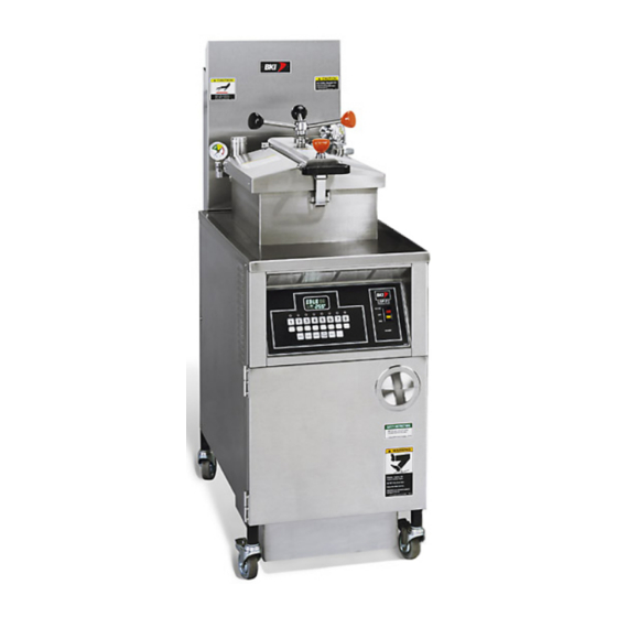
Gas pressure fryer
Hide thumbs
Also See for LGF-F:
- Operation manual (45 pages) ,
- Service manual (60 pages) ,
- Installation and operation manual (56 pages)

Related Manuals for BKI LGF-F


Summary of Contents for BKI LGF-F
- Page 1 Gas Pressure Fryer MODELS LGF-F, & LGF-FC Service Manual Serial Numbers 137733 and higher...
- Page 2 Warranty Information LIMITED ONE YEAR WARRANTY BKI (The "Company") warrants to the original purchaser that at time of shipment from the Company factory, this equipment will be free from defect in materials and workmanship. Written notice of a claim under this warranty must be received by the Company within ONE YEAR from the date of installation, but no longer than ONE YEAR AND THREE MONTHS from date of shipment from the factory.
-
Page 3: Table Of Contents
Operation ..............................12 Controls and Indicators........................... 12 Care of the Shortening..........................15 LGF-F Operation............................. 16 Start-Up (LGF-F) ..........................16 Cooking with the LGF-F ........................17 LGF-FC Operation ..........................19 Computer Programming ........................19 Product Programming ........................21 Start-Up (LGF-FC)..........................24 Cooking with the LGF-FC........................ -
Page 4: Introduction
PERFECTION IN PRESSURE FRYING! The BKI name and trademark on this unit assures you of the finest in design and engineering -- that it has been built with care and dedication -- using the best materials available. Attention to the operating instructions regarding proper installation, operation, and maintenance will result in long lasting dependability to insure the highest profitable return on your investment. -
Page 5: Specific Precautions
These sparks could cause serious injury, damage, or fire. BKI provides an Equipotential ground terminal for the connection of a bonding conductor after the installation of the appliance per lEC60417-1. This terminal is located on the inside of the Power Entry Supply box near the Earth connection and is marked with this symbol. -
Page 6: Safe Work Practices
Gas Pressure Fryer Introduction Safe Work Practices Do Not Store Or Use Anything Flammable Near The Fryer Your pressure fryer utilizes either Natural or LP gas and an open flame. Do not store flammable liquids or allow flammable vapors near this appliance. Flammable materials burn easily. Allowing flammable liquid or vapor near the fryer could cause an explosion and/or fire. - Page 7 Gas Pressure Fryer Introduction Keep The Area Around Your Fryer Uncluttered Make sure to keep the area around your fryer clear of any obstacles. Serious injury can occur if you trip or fall near the fryer. You could be burned by hot shortening that splashes out of the fryer or by falling against the hot metal of the fryer.
- Page 8 If you lose or damage your mitts, you can buy new ones at your local restaurant equipment supply store or from your local BKI Distributor. Always wear non-skid shoes when working around the fryer or any other equipment that uses shortening.
- Page 9 Gas Pressure Fryer Introduction Never Loosen The Spin Handle Until The Pressure Gauge Is At Zero Serious Injury may result as Hot Shortening and Steam may escape suddenly if you loosen the spin handle before the gauge is at zero. After the pressure gauge is at zero, wait 5 seconds.
- Page 10 Gas Pressure Fryer Introduction Keep Safety Labels Clean and in Good Condition Do not remove or cover any safety labels on your equipment. Keep all safety labels clean and in good condition. Replace any damaged or missing safety labels. Refer to the Safety Labels section for illustration and location of safety labels on this unit.
-
Page 11: Safety Labels
Gas Pressure Fryer Introduction Safety Labels... - Page 12 Gas Pressure Fryer Introduction...
-
Page 13: Installation
Gas Pressure Fryer Installation Installation For installation information, refer to Gas Pressure Fryer, MODELS LGF-F & LGF-FC, Installation Manual LI0298. -
Page 14: Operation
Gas Pressure Fryer Operation Operation Controls and Indicators Refer to the figure and table below for an explanation of the fryer’s controls and indicators. - Page 15 Gas Pressure Fryer Operation Item Description Function Pressure Gauge Indicates the pressure inside the pot. Spin Handle Used to tighten the lid to the pot once it is latched. Pop Safety Valve lever Used to release pressure periodically to prevent the seat from sticking.
- Page 16 Gas Pressure Fryer Operation Item Description Function A, B, C, D preset These buttons are used to save and recall preset cycle and alarm buttons times, saving operator time and minimizing error when changing interval cycle times and alarm times. To save the current interval and alarm times into one of the preset locations, press and hold the A, B, C, or D preset button for 2 seconds and the controller will double chirp to indicate the times have been saved.
-
Page 17: Care Of The Shortening
DO NOT HOLD SHORTENING AT HIGH TEMPERATURE when the fryer is not in use. If you expect an elapsed time of one hour or more between cooking, close the lid and press the “0” button on the LGF-FC model. On Models LGF and LGF-F, set the thermostat to 150º F. •... -
Page 18: Lgf-F Operation
Do not use any shortening other than what is specified in this manual and do not overfill the fryer pot. The LGF/LGF-F fryer has a maximum temperature setting of 375º F (190º C). Do not use oil/shortening with a flashpoint less than 554º F (290º C) Use only high-quality shortening that has low moisture content, a high smoke point and no additives. -
Page 19: Cooking With The Lgf-F
7. The shortening will heat and begin to reach the fill mark inside the pot. Add more shortening as required to reach the fill mark. Cooking with the LGF-F Do not open the drain valve or the fill valve while the fryer is under pressure. - Page 20 Gas Pressure Fryer Operation 9. At the end of the frying cycle, the digital timer beeper will sound and the fryer will automatically release pressure into the baffle box. Press the START/STOP button. 10. When the pointer on the pressure gauge is at zero, wait 5 seconds then slowly turn the spin handle counterclockwise to break the seal around the lid.
-
Page 21: Lgf-Fc Operation
Gas Pressure Fryer Operation LGF-FC Operation Computer Programming Use the following figure and table to set options that apply to each product program. Figure 1. System Programming Sequence... - Page 22 Gas Pressure Fryer Operation Table 1. System Programming Procedure STEP ACTION DISPLAY COMMENTS Press the FILTER/OFF/FRY switch to FRY. Press PROG on the keypad. PROGRAM CODE Input 1712 and ENTER. PROGRAM SYSTEM Press ENTER. PROGRAM DEGREES This command allows you to °F choose the temperature scale option you want to use.
-
Page 23: Product Programming
Gas Pressure Fryer Operation Product Programming Use the following figure and table to set a maximum of eight product programs. The product programs must be set before cooking can begin. Figure 2. Product Programming Sequence... - Page 24 Gas Pressure Fryer Operation Table 2. Product Programming Procedure STEP ACTION DISPLAY COMMENTS Press the FILTER/OFF/FRY switch to FRY. Press PROG on the keypad. PROGRAM CODE Input 1724 and press ENTER. PROGRAM PRODUCT Select the program product PROGRAM PRODUCT X refers to the program number (1-8).
- Page 25 Gas Pressure Fryer Operation STEP ACTION DISPLAY COMMENTS Repeat steps 5-12 when The time and temperature of programming stages 2, 3, 4 each stage has to be less than and 5 for Electric and Gas the preceding stage. appliance types. Repeat steps 5-10 when programming stages 2, 3, 4 and 5 for an ALF appliance...
-
Page 26: Start-Up (Lgf-Fc)
Gas Pressure Fryer Operation Start-Up (LGF-FC) 1. Make sure the main drain valve is closed. 2. Fill pot with shortening to about one inch below the mark. Risk of fire exists if the oil level drops below the minimum oil level. The level of oil within the pot must not fall below 5mm of the maximum oil level. - Page 27 Gas Pressure Fryer Operation 4. Carefully drop the chicken in the shortening one piece at a time starting with thighs and drumsticks, followed by breast and wings. The fryer will accommodate 32 pieces of chicken. Failure to use the insulated mitts will result in severe injury. Always use the insulated mitts when handling the hot fry basket.
-
Page 28: Operation After Gas Or Power Outage
Gas Pressure Fryer Operation Operation After Gas or Power Outage The fryer may shut off automatically if the gas supply is interrupted or the power goes out. If either of these conditions occur you should perform the following procedure: For your safety, if the gas supply stops, or, if the power goes out, make sure to wait for at least five minutes before restarting your fryer. - Page 29 Gas Pressure Fryer Operation Fresh Chicken Use fresh 8 or 9-piece cut chicken. Use 2-1/2 to 3 pounds for best results. 1. Rinse product under cold water. 2. Bread each piece with Imperial breading. 3. Place product into fryer basket. 4.
- Page 30 Gas Pressure Fryer Operation Milanese It is best to use 5 to 7 ounce beef steaks. 1. Season and bread each steak as desired. 2. Place steaks into fryer basket. 3. Close cover to begin pressure frying. 4. Cook for 5 to 6 minutes at 325°F depending on size. Fresh Shrimp 1.
-
Page 31: Maintenance
Gas Pressure Fryer Maintenance Maintenance For maintenance information, refer to Gas Pressure Fryer, MODELS LGF-F & LGF-FC, Operation Manual LI0293. -
Page 32: Replacement Parts
Use the information in this section to identify replacement parts. To order replacement parts, call your local BKI sales and service representative. Before calling, please note the serial number, model number and voltage on the rating tag affixed to the unit. - Page 33 Gas Pressure Fryer Replacement Parts Figure 3. Lid/Arm Assembly, AN3211350S (Sheet 1 of 4)
- Page 34 Gas Pressure Fryer Replacement Parts Figure 3. Lid/Arm Assembly, AN3211350S (Sheet 2 of 4)
- Page 35 Gas Pressure Fryer Replacement Parts Figure 3. Lid/Arm Assembly, AN3211350S (Sheet 3 of 4)
- Page 36 Gas Pressure Fryer Replacement Parts Figure 3. Lid/Arm Assembly, AN3211350S (Sheet 4 of 4)
- Page 37 Gas Pressure Fryer Replacement Parts Table 3. Lid/Arm Assembly (AN3211350S) Parts ITEM # PART # DESCRIPTION Figure 3 (sheet 1) AN3211350S LID/ARM ASSY Figure 3 (sheet 2) H0157 HANDLE, SPIN FOR FRYERS FT0332 STUD, 5.5” TIGHTEN DN HN K0003 KNOB, BLACK #85C K0020 HUB, TIGHTEN DOWN K0043...
- Page 38 Gas Pressure Fryer Replacement Parts Figure 4. Dead Weight & Pressure Gauge Assembly...
- Page 39 Gas Pressure Fryer Replacement Parts Table 4. Dead Weight & Pressure Gauge Assembly Parts ITEM # PART # DESCRIPTION C0657 COVER, DEAD WEIGHT VALVE FKM W0201 WEIGHT, VALVE FKM 12# O0001 ORIFICE, SS FT0414 NIPPLE, 1/2 X 3 3/4 SS SCH 80 B0965 BODY, DEAD WEIGHT VALVE LGF SS FT0232...
- Page 40 Gas Pressure Fryer Replacement Parts Figure 5. Drain/Motor/Piping Assembly...
- Page 41 Gas Pressure Fryer Replacement Parts Table 5. Drain/Motor/Piping Assembly Parts ITEM # PART # DESCRIPTION TU0205 TUBING, 12" 1/2" ID FT0536 COUPLING, 5/8 45¦ FLARE TO M0053 MOTOR, LEESON LESS CORD/PUMP P0070 PUMP ONLY FOR HAIGHT MOTOR FT0538 TEE, 1/2 X 1/2 X 3/8 BLK FT0507 CONNECTOR, MALE 10FBU-S NKL PLTD FT0412...
- Page 42 Gas Pressure Fryer Replacement Parts Figure 6. Burner Tray Assembly (Sheet 1 of 2)
- Page 43 Gas Pressure Fryer Replacement Parts Figure 6. Burner Tray Assembly (Sheet 2 of 2)
- Page 44 Gas Pressure Fryer Replacement Parts Table 6. Burner Tray Assembly Parts ITEM # PART # DESCRIPTION AN32200100 NATURAL GAS CONVERSION KIT LGFA053 BURNER ORIFICE, NATURAL O0005 N0304 NATURAL GAS DECAL O0007 PILOT ASSEMBLY ORIFICE - 45.900.421-027 SCR336 SCREW, 10-24 X 1 PHIL TRUSS SCR383 SCREW, 10-24 X 1/2"...
- Page 45 Gas Pressure Fryer Replacement Parts Figure 7. Control Panel (AB32200900) LGF-F...
- Page 46 Gas Pressure Fryer Replacement Parts Table 7. Control Panel (AB32200900) LGF-F Parts ITEM # PART # DESCRIPTION B1050 BEZEL, ROBERTSHAW THERMOSTAT K0030 KNOB, T-STAT BLK 400DEG N0572 DECAL, CONTROL LGF-F EXPORT PL0004 PILOT LIGHT, SOLICO S0104 SWITCH, RKR DPDT 15A 250V LAMP S0166 ROCKER SWITCH, MARQUARDT # 18.01.1202...
- Page 47 Gas Pressure Fryer Replacement Parts Figure 8. Control Panel (AB32200700) LGF-FC...
- Page 48 Gas Pressure Fryer Replacement Parts Table 8. Control Panel (AB32200700) LGF-FC Parts ITEM # PART # DESCRIPTION CP0039 CONTROLLER, VFD LESS HARNESS VR081LM61001 N0573 DECAL, CONTROL LGF-FC EXPORT S0165 OVERTEMPERATURE SWITCH, THERMODISC # 36TXE22 PL0004 PILOT LIGHT, SOLICO R0174 RELAY, OMRON # G8P-1C2T-F S0104 SWITCH, RKR DPDT 15A 250V LAMP S0166...
- Page 49 Gas Pressure Fryer Replacement Parts Figure 9. Door Assembly W/Pocket (SB3290)
- Page 50 Gas Pressure Fryer Replacement Parts Table 9. Door Assembly W/Pocket (SB3290) Parts ITEM # PART # DESCRIPTION H0010 HINGE, DOOR, LH, PIN SIDE FRY.DOORS N0059 DECAL, SMALL BRUSH/ N0165 DECAL, NOTICE LOST MANUAL N0169 DECAL, MANUAL GAS SHUT OFF N0527 DECAL, SAFETY INSTR FRYERS N0175 DECAL, SLIPPING ADMONITIONS...
- Page 51 Gas Pressure Fryer Replacement Parts Figure 10. Oil Vat Assembly (AN32112800)
- Page 52 Gas Pressure Fryer Replacement Parts Table 10. Oil Vat Assembly (AN32112800) Parts ITEM # PART # DESCRIPTION AN86208400 FILTER SCREEN ASSY, LGF SB1991 QUIK DISCONNECT BRACKET WELDMENT O0013 O-RING, FLUOROCARBON V680-70 WB86202700 FILTER TUBING/DISCONN ALF LGF LPF SB7659 FILTER SCREEN FITTING SPOTWELD FS0003 FILTER SCREEN, TOP FS0002...
- Page 53 Gas Pressure Fryer Replacement Parts Figure 12. Solenoid Valve Assembly Table 12. Solenoid Valve Assembly Parts ITEM # PART # DESCRIPTION FT0235 NIPPLE, 1/2 X C SS FT0198 TEE, BRASS 1/2" CP SV0004 VALVE, SOLENOID HV-214-761-2 120V FT0413 NIPPLE, 1/2 X 1 3/4 SS FT0414 NIPPLE, 1/2 X 3 3/4 SS FT0067...
- Page 54 Gas Pressure Fryer Replacement Parts Figure 13. Quick Disconnect Assembly (SB1997S) Table 13. Quick Disconnect Assembly (SB1997S) Parts ITEM # PART # DESCRIPTION B0996 BALL, 11/16" STEEL BEARING FT0429 QUICK DISCONNECT, PUMP SIDE FT0500 QUICK DISCONNECT, VAT SIDE FT0536* COUPLING, 5/8 45¦ FLARE TO O0013 O-RING, FLUOROCARBON V680-70 O0014...
- Page 55 Gas Pressure Fryer Replacement Parts Figure 14. Drain Valve & Plugs (SB1999S) Table 14. Drain Valve & Plugs (SB1999S) Parts ITEM # PART # DESCRIPTION MB19101000 DRAIN VALVE REPLACEMENT FT0243 PLUG, 3/8" SQ HEAD PIPE...
-
Page 56: Accessories
Gas Pressure Fryer Replacement Parts Accessories Description Accessory # Figure # Item # BASKET, LGF B0108B Figure 15 HANDLE, TEE STYLE LIFT H0151 Figure 15 BRUSH, DRAIN (LONG WHITE) B0075 Figure 15 BRUSH, LONG #5702 B0051 Figure 15 BRUSH, POT SCRUBBER, WHITE B0049 Figure 15 BRUSH, SHORT #6175... -
Page 57: Components
Gas Pressure Fryer Replacement Parts Components Description Component # Figure # Item # ARM ADJUSTABLE STOP /FKM A0101 Figure 16 CASTER, 2470-DIK-075-R05/22 C0409 Figure 16 CASTER, 2477-DIK-075-R05/22 C0410 Figure 16 FILTER BAG CLIP FI0007 ST0015 Figure 16 FILTER, FKM-F 13.5 X 20.5 FI0007 Figure 16 THERMISTER PROBE, 6.85 X 1... -
Page 58: Wiring Diagrams
Gas Pressure Fryer Wiring Diagrams Wiring Diagrams... - Page 59 Gas Pressure Fryer Wiring Diagrams...
- Page 60 P.O. Box 80400, Simpsonville, S.C. 29680-0400, USA http://www.bkideas.com Made and printed in the U.S.A LI0294/0808...
Need help?
Do you have a question about the LGF-F and is the answer not in the manual?
Questions and answers