BKI ALF-F Service Manual
Automatic lift fryer
Hide thumbs
Also See for ALF-F:
- Installation and operation manual (32 pages) ,
- Installation & operation manual (32 pages)

Related Manuals for BKI ALF-F


Summary of Contents for BKI ALF-F
- Page 1 Automatic Lift Fryer MODELS ALF-F, & ALF-FC Service Manual Serial Numbers 137733 and higher...
-
Page 2: Warranty Information
Warranty Information LIMITED ONE YEAR WARRANTY BKI (The "Company") warrants to the original purchaser that at time of shipment from the Company factory, this equipment will be free from defect in materials and workmanship. Written notice of a claim under this warranty must be received by the Company within ONE YEAR from the date of installation, but no longer than ONE YEAR AND THREE MONTHS from date of shipment from the factory. -
Page 3: Table Of Contents
Wiring... 9 Initial Test and Adjustment ... 10 Operation ... 11 Controls and Indicators... 11 Care of the Shortening... 14 ALF-F Operation ... 14 Start-Up ... 14 Cooking ... 16 ALF-FC Operation ... 17 System Programming ... 17 Product Programming ... 19 Start-Up ... -
Page 4: Introduction
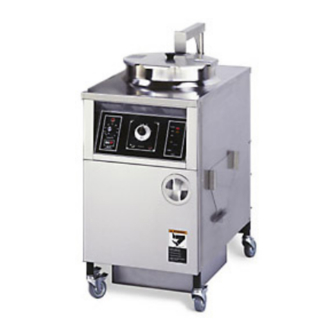
Automatic Lift Fryer The ALF Fryer is compact, attractive and functional in design. It is constructed of a stainless steel fryer pot for cleaning ease. Exclusive BKI patented features and safety devices offer flexibility, efficiency and reliability plus PERFECTION IN FRYING! The BKI name and trademark on this unit assures you of the finest in design and engineering -- that it has been built with care and dedication -- using the best materials available. -
Page 5: Specific Precautions
Follow the oil manufacturers guidelines for the life cycle of oil/shortening. Do not open the drain valve or the fill valve while the fryer is under pressure. Serious burns may result. -
Page 6: Safe Work Practices
Make sure to keep the area around your fryer clear of any obstacles. Serious injury can occur if you trip or fall near the fryer. You could be burned by hot shortening that splashes out of the fryer or by falling against the hot metal of the fryer. - Page 7 Always wear your insulated mitts when handling the fryer basket or touch any hot metal surfaces. You received a pair of insulated mitts with your fryer. If you lose or damage your mitts, you can buy new ones at your local restaurant equipment supply store or from your local BKI Distributor.
-
Page 8: Protect Children
Automatic Lift Fryer Introduction Keep this manual with the Equipment This manual is an important part of your equipment. Always keep it near for easy access. If you need to replace this manual, contact: Technical Services Department P.O. Box 80400 Simpsonville, S.C. -
Page 9: Be Prepared For Emergencies
Automatic Lift Fryer Be Prepared for Emergencies Be prepared for fires, injuries, or other emergencies. Keep a first aid kit and a fire extinguisher near the equipment. You must use a 40-pound Type BC fire extinguisher and keep it within 25 feet of your equipment. -
Page 10: Safety Labels
Automatic Lift Fryer Introduction Safety Labels... -
Page 11: Installation
Attach the spring-loaded hook on the restraining device to the eye-bolt mounted to the fryer then attach the other spring-loaded hook to the wall attachment. 3. Lock the casters so the fryer does not move. Every time the fryer is used, make sure the casters are locked so the fryer cannot move. -
Page 12: Initial Test And Adjustment
The fryer has a maximum temperature setting of 375º F/190º C (for ALF and ALF-F) or 390º F/200º C (for ALF-FC). Do not use oil/shortening with a flashpoint less than 554º F (290º C) Use only high-quality shortening that has low moisture content, a high smoke point and no additives. -
Page 13: Operation
Automatic Lift Fryer Operation Operation Controls and Indicators Refer to the figure and table below for an explanation of the fryer’s controls and indicators. - Page 14 Automatic Lift Fryer Item # Description Computer Momentary Basket Switch Rocker Switch Thermostat Knob Thermostat Light Digital Timer LED indicator TIME SELECT (2 arrow buttons) START/STOP button Function Used to set and activate product programs. UP – Momentarily pushing the switch to this position causes the lift mechanism to rise.
- Page 15 Automatic Lift Fryer Item # Description ALARM button A, B, C, D preset buttons Beeper Display High Limit Reset Switch Drain Lever Fill Lever Rinse Hose Connector Pump Motor Reset Switch Function This button allows the user to set an elapsed time at which the internal alarm will sound during a cycle.
-
Page 16: Care Of The Shortening
The fryer has a maximum temperature setting of 375º F/190º C (for ALF and ALF-F) or 390º F/200º C (for ALF-FC). Do not use oil/shortening with a flashpoint less than 554º F (290º C) Use only high-quality shortening that has low moisture content, a high smoke point and no additives. - Page 17 4. Set the thermostat to the desired cook temperature. The temperature light will go on. When the temperature is reached, the light will go off. The light will continue to cycle on and off as the fryer maintains the set temperature.
-
Page 18: Cooking
9. Remember to filter the shortening at least every third frying cycle load. Refer to the procedure in this manual. Also filter the shortening and clean the fryer at the end of each day. If you do not plan to use the fryer for an hour or more, turn the thermostat down to 150°. -
Page 19: Alf-Fc Operation
Automatic Lift Fryer Operation ALF-FC Operation System Programming Use the following figure and table to set options that apply to each product programs. Figure 1. System Programming Sequence... - Page 20 Automatic Lift Fryer Table 1. System Programming Procedure STEP ACTION Press the FILTER/OFF/FRY switch to FRY. Press PROG on the keypad. Input 1712 and ENTER. Press ENTER. Press TOGGLE/CLEAR until the desired option is displayed. Press ENTER. Press TOGGLE/CLEAR until the desired option is displayed.
-
Page 21: Product Programming
Automatic Lift Fryer Operation Product Programming Use the following figure and table to set a maximum of eight product programs. The product programs must be set before cooking can begin. Figure 2. Product Programming Sequence... - Page 22 The FLEX TIME option will allow the fryer to recover from temperature loss. PROGRAM TEMPCOM1 X refers to the temperature compensation option selected.
- Page 23 Automatic Lift Fryer STEP ACTION Press TOGGLE/CLEAR until the desired option is displayed. Repeat steps 5-12 when programming stages 2, 3, 4 and 5 for Electric and Gas appliance types. Repeat steps 5-10 when programming stages 2, 3, 4 and 5 for an ALF appliance type.
-
Page 24: Start-Up
The fryer has a maximum temperature setting of 375º F/190º C (for ALF and ALF-F) or 390º F/200º C (for ALF-FC). Do not use oil/shortening with a flashpoint less than 554º F (290º C) Use only high-quality shortening that has low moisture content, a high smoke point and no additives. - Page 25 11. Press the 0 button. Idle 255°F will display. This will automatically hold the shortening at a cooler temperature. 12. To escape the idle mode, press the 0 button again and the fryer will heat to its original temperature. 13. When you have finished frying for the day, turn the FILTER/OFF/FRY switch to the OFF position.
-
Page 26: Maintenance
Failure to comply with the maintenance below could result in a serious accident. Your fryer will need periodic maintenance and servicing. We strongly suggest that you use only a service company that is authorized by BKI to do this work. -
Page 27: Filtering Procedure
We recommend the shortening be filtered after every three frying cycle loads. If the shortening starts to show signs of foaming or has a bad taste, do not use it. The fryer pot should be cleaned before refilling with new shortening. Best results for filtering are obtained while the shortening is hot. -
Page 28: Boil-Out Procedure
2. Drain the clean shortening into an adequate storage container. (Allow the shortening to cool to room temperature before attempting storage.) 3. CLOSE the drain and fill the fryer pot with HOT water to the shortening level fill mark. Do not overfill by allowing the water level higher than the fill mark. - Page 29 12. Rinse the pot with hot water, using the pot brush to remove remaining sediment, drain and discard. 13. Close the drain and refill the fryer pot with hot water to the proper level. 14. Add approximately 4 to 6 ounces of distilled (white) vinegar to develop a neutralizing solution. Stir the solution briefly.
-
Page 30: Filter Pad Replacement
Automatic Lift Fryer Filter Pad Replacement The filter pad must be replaced daily. If the shortening has a milky color when it is pumped into the pot, the filter pad should be replaced immediately. If the filter pad is not properly closed, breading crumbs will get through the pad opening and clog the pump. -
Page 31: Troubleshooting
Automatic Lift Fryer Troubleshooting Refer to the table below for troubleshooting information. Problem Shortening Heating Too Slowly Filter System Not Working Computer Hangs Cause Possible Solution Low voltage or improper Contact an authorized BKI service voltage agent for corrective action. -
Page 32: Replacement Parts
Assemblies Description DRAIN VALVE & PLUGS DOOR ASSEMBLY DRAIN/MOTOR/PIPING ASSEMBLY CONTROL PANEL ALF-F (1/3 Phase) CONTROL PANEL ALF-F (3 Phase) CONTROL PANEL ALF-FC (1/3 Phase) CONTROL PANEL ALF-FC (3 Phase) OIL VAT ASSEMBLY QUICK DISCONNECT ASSEMBLY... - Page 33 Automatic Lift Fryer Figure 3. Drain Valve & Plugs (SB1999S) Table 3. Drain Valve & Plugs (SB1999S) Parts ITEM # PART # MB19101000 FT0243 DESCRIPTION DRAIN VALVE REPLACEMENT PLUG, 3/8" SQ HEAD PIPE Replacement Parts...
- Page 34 Automatic Lift Fryer Table 4. Door Assembly (SB1289) Parts ITEM # PART # F0083 H0010 N0165 N0175 N0176 N0527 P0022 RIV172 SB1290 SCR008 SCR075 WLPFA096 H0009 Figure 4. Door Assembly (SB1289) THREAD INSERT 10-24 STEEL HINGE, LH PIN HALF DECAL, NOTICE LOST MANUAL DECAL, SLIPPING ADMONITIONS DECAL, INSTR &...
- Page 35 Automatic Lift Fryer Replacement Parts Figure 5. Drain/Motor/Piping Assembly...
- Page 36 Automatic Lift Fryer Table 5. Drain/Motor/Piping Assembly Parts ITEM # PART # D0060 FT0044 FT0412 SB1314 FT0538 FT0507 FT0536 FT0543 TU0206 TU0205 P0070 F0254 F0255 F0253 SP0014 SP0034 NUT253 FT0022 LZ0130 S0054 LPFFA093 N0277 SCR194 H0214 C0672 SCR006 LPFFA092 C0668...
- Page 37 Automatic Lift Fryer Replacement Parts Figure 6. Control Panel ALF-F...
- Page 38 T0036 R0131 TI0032 S0104 S0127 SB0197 N0424 Table 6. Control Panel ALF-F Parts DESCRIPTION KNOB, S/S STRAT T0075 THERMOSTAT, SOLID STATE FRYER PILOT LIGHT, ROUND 250V RELAY, MERCURY MDI 60NO220A (AN15210700) RELAY, MERCURY MDI 60NO220A (AN15210600) RELAY, 4 POLE 208-240 60 HZ (AN15210700)
- Page 39 Automatic Lift Fryer Replacement Parts Figure 7. Control Panel ALF-FC...
- Page 40 FUSE, 15A 300V SC15 TIME DELAY FUSE HOLDER, 15A 300V HPF-EE THERMOSTAT, HI LIMIT 540 DEG TRANSFORMER ASSY 240V RELAY, X-40, SGL FRYER RELAY. PLUG IN 3PDT 240V COIL SWITCH, RKR DPDT 15A 250V LAMP SWITCH, ROCKER 2P, 3 POS...
- Page 41 Automatic Lift Fryer Replacement Parts Figure 8. Oil Vat Assembly (AN86202800)
- Page 42 Automatic Lift Fryer Table 8. Oil Vat Assembly (AN86202800) Parts ITEM # PART # SB1991 O0013 WB86202700 SB7659 FS0003 FS0002 FS0001 FC0004 WB32112600 FB86202502 N0395 SB2306 DESCRIPTION QUIK DISCONNECT BRACKET WELDMENT O-RING, FLUOROCARBON V680-70 FILTER TUBING/DISCONN ALF LGF LPF FILTER SCREEN FITTING SPOTWELD...
-
Page 43: Components
Automatic Lift Fryer Table 9. Quick Disconnect Assembly Parts ITEM # PART # AB86200700 B0996 FT0429 FT0500 FT0536 O0013 O0014 S0138 SCR453 SB1997S B0996 FT0429 FT0500 O0013 O0014 S0138 Components Description CALROD, 208V 4500W LPF (W) CALROD, 240V 4500W LPF (W) - Page 44 Automatic Lift Fryer Figure 10. Components Replacement Parts...
-
Page 45: Accessories
BRUSH, DRAIN (LONG WHITE) BRUSH, L TIPPED 40152 BRUSH, POT SCRUBBER, WHITE FILTER HOSE, FEMALE SOCKET - option GLOVE, NEOPRENE FILTER, LPF-F 13.5 X 20.5 BASKET, ALF BAIL HANDLE FILTER VAT DOLLY ALF-F- option RESTRAINT STORAGE COVER- option Accessory # B0115B H0151 B0075... - Page 46 Automatic Lift Fryer Figure 12. Storage Cover Assembly (Optional) ITEM # PART # ALFA123 SCR136 N0358 K0044 ALFA122 N0162 SCR007 SCR005 Table 10. Storage Cover Assembly Parts HANGER, FRY POT COVER SCREW, 10-24 X 3/8 SLTD TRUSS DECAL, BLF COVER CAUTION...
-
Page 47: Wiring Diagrams
Automatic Lift Fryer Refer to the table below to find the wiring diagram associated with your unit. Wiring Diagram ALF-F 208V/240V, 3 Phase ALF-F 208V/240V, 1/3 Phase ALF-FC 208V/240V, 1/3 Phase ALF-FC 208V/240V, 3 Phase Wiring Diagrams Diagram # SB15291100... - Page 48 Automatic Lift Fryer Wiring Diagrams Figure 13. ALF-F 208V 3 Phase or ALF-F 240V 3 Phase...
- Page 49 Automatic Lift Fryer Wiring Diagrams Figure 14. ALF-F 208V/240V, 1/3 Phase...
- Page 50 Automatic Lift Fryer Wiring Diagrams Figure 15. ALF-FC 208V 1/3 Phase or ALF-FC 240V 1/3 Phase (Sheet 1 of 3)
- Page 51 Automatic Lift Fryer Wiring Diagrams Figure 15. ALF-FC 208V 1/3 Phase or ALF-FC 240V 1/3 Phase (Sheet 2 of 3)
- Page 52 Automatic Lift Fryer Wiring Diagrams Figure 15. ALF-FC 208V 1/3 Phase or ALF-FC 240V 1/3 Phase (Sheet 3 of 3)
- Page 53 Automatic Lift Fryer Wiring Diagrams Figure 16. ALF-FC 208V/240V/3 Phase (sheet 1 of 3)
- Page 54 Automatic Lift Fryer Wiring Diagrams Figure 16. ALF-FC 208V/240V/3 Phase (sheet 2 of 3)
- Page 55 Automatic Lift Fryer Wiring Diagrams Figure 16. ALF-FC 208V/240V/3 Phase (sheet 3 of 3)
-
Page 56: Notes
Automatic Lift Fryer Notes Notes... - Page 57 Automatic Lift Fryer...
- Page 58 Automatic Lift Fryer...
- Page 59 Automatic Lift Fryer...
- Page 60 P.O. Box 80400, Simpsonville, S.C. 29680-0400, USA http://www.bkideas.com Made and printed in the U.S.A LI0228/0808...
Need help?
Do you have a question about the ALF-F and is the answer not in the manual?
Questions and answers