BKI BLF-F Service Manual
Bki automatic lift fryer service manual
Hide thumbs
Also See for BLF-F:
- Service manual (56 pages) ,
- Installation & operation manual (42 pages) ,
- Installation and operation manual (32 pages)

Subscribe to Our Youtube Channel
Related Manuals for BKI BLF-F


Summary of Contents for BKI BLF-F
- Page 1 Automatic Lift Fryer MODELS BLF-F, & BLF-FC Service Manual Serial Numbers 137733 and higher...
-
Page 2: Warranty Information
Warranty Information LIMITED ONE YEAR WARRANTY BKI (The "Company") warrants to the original purchaser that at time of shipment from the Company factory, this equipment will be free from defect in materials and workmanship. Written notice of a claim under this warranty must be received by the Company within ONE YEAR from the date of installation, but no longer than ONE YEAR AND THREE MONTHS from date of shipment from the factory. -
Page 3: Table Of Contents
Safety Labels... 8 Installation ... 9 Operation ... 10 Controls and Indicators... 10 Care of the Shortening... 13 BLF-F Operation ... 13 Start-Up ... 13 Cooking ... 14 BLF-FC Operation ... 16 System Programming ... 16 Product Programming ... 18 Start-Up ... -
Page 4: Introduction
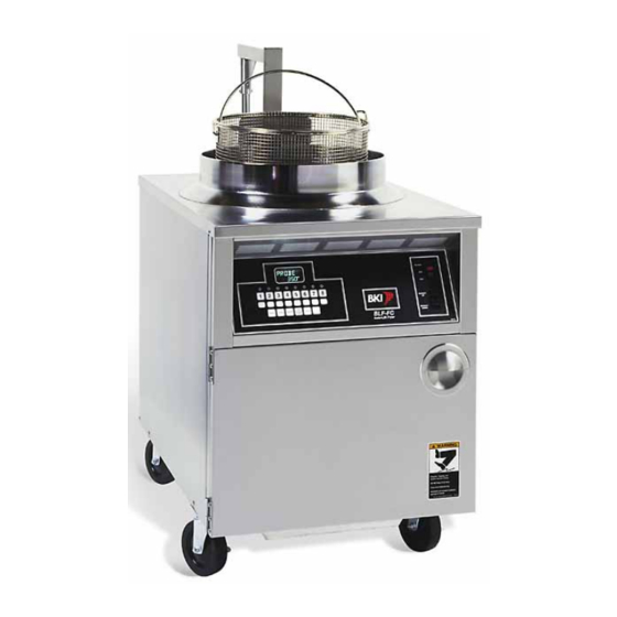
Automatic Lift Fryer The BLF Fryer is compact, attractive and functional in design. It is constructed of a stainless steel fryer pot for cleaning ease. Exclusive BKI patented features and safety devices offer flexibility, efficiency and reliability plus PERFECTION IN FRYING! The BKI name and trademark on this unit assures you of the finest in design and engineering -- that it has been built with care and dedication -- using the best materials available. -
Page 5: Specific Precautions
Follow the oil manufacturers guidelines for the life cycle of oil/shortening. Do not open the drain valve or the fill valve while the fryer is under pressure. Serious burns may result. -
Page 6: Safe Work Practices
Make sure to keep the area around your fryer clear of any obstacles. Serious injury can occur if you trip or fall near the fryer. You could be burned by hot shortening that splashes out of the fryer or by falling against the hot metal of the fryer. - Page 7 Always wear your insulated mitts when handling the fryer basket or touch any hot metal surfaces. You received a pair of insulated mitts with your fryer. If you lose or damage your mitts, you can buy new ones at your local restaurant equipment supply store or from your local BKI Distributor.
-
Page 8: Protect Children
Automatic Lift Fryer Introduction Keep this manual with the Equipment This manual is an important part of your equipment. Always keep it near for easy access. If you need to replace this manual, contact: Technical Services Department P.O. Box 80400 Simpsonville, S.C. -
Page 9: Be Prepared For Emergencies
Automatic Lift Fryer Be Prepared for Emergencies Be prepared for fires, injuries, or other emergencies. Keep a first aid kit and a fire extinguisher near the equipment. You must use a 40-pound Type BC fire extinguisher and keep it within 25 feet of your equipment. -
Page 10: Safety Labels
Automatic Lift Fryer Introduction Safety Labels... -
Page 11: Installation
Automatic Lift Fryer Installation Installation For installation information, refer to Automatic Lift Fryer, MODELS BLF-F, & BLF-FC, Installation and Operation Manual LI0225. -
Page 12: Operation
Automatic Lift Fryer Operation Operation Controls and Indicators Refer to the figure and table below for an explanation of the fryer’s controls and indicators. - Page 13 Automatic Lift Fryer Item # Description Computer Momentary Switch Rocker Switch Thermostat Knob Thermostat Light Digital Timer LED indicator TIME SELECT (2 arrow buttons) START/STOP button Function Used to program the cooking computer and activate the programs. BASKET UP – Momentarily pushing the switch to this position causes the lift mechanism to rise.
- Page 14 Automatic Lift Fryer Item # Description ALARM button A, B, C, D preset buttons Beeper Display High Limit Reset Switch Drain Lever Fill Lever Rinse Hose Connector Pump Motor Reset Switch Function This button allows the user to set an elapsed time at which the internal alarm will sound during a cycle.
-
Page 15: Care Of The Shortening
The fryer has a maximum temperature setting of 375º F/190º C (for BLF and BLF-F) or 390º F/200º C (for BLF-FC). Do not use oil/shortening with a flashpoint less than 554º F (290º C) Use only high-quality shortening that has low moisture content, a high smoke point and no additives. -
Page 16: Cooking
4. Set the thermostat to the desired cook temperature. The temperature light will go on. When the temperature is reached, the light will go off. The light will continue to cycle on and off as the fryer maintains the set temperature. - Page 17 9. Remember to filter the shortening at least every third frying cycle load. Refer to the procedure in this manual. Also filter the shortening and clean the fryer at the end of each day. If you do not plan to use the fryer for an hour or more, turn the thermostat down to 150°.
-
Page 18: Blf-Fc Operation
Automatic Lift Fryer Operation BLF-FC Operation System Programming Use the following figure and table to set options that apply to each product programs. Figure 1. System Programming Sequence... - Page 19 Automatic Lift Fryer Table 1. System Programming Procedure STEP ACTION Press the FILTER/OFF/FRY switch to FRY. Press PROG on the keypad. Input 1712 and ENTER. Press ENTER. Press TOGGLE/CLEAR until the desired option is displayed. Press ENTER. Press TOGGLE/CLEAR until the desired option is displayed.
-
Page 20: Product Programming
Automatic Lift Fryer Operation Product Programming Use the following figure and table to set a maximum of eight product programs. The product programs must be set before cooking can begin. Figure 2. Product Programming Sequence... - Page 21 The FLEX TIME option will allow the fryer to recover from temperature loss. PROGRAM TEMPCOM1 X refers to the temperature compensation option selected.
- Page 22 Automatic Lift Fryer STEP ACTION Press TOGGLE/CLEAR until the desired option is displayed. Repeat steps 5-12 when programming stages 2, 3, 4 and 5 for Electric and Gas appliance types. Repeat steps 5-10 when programming stages 2, 3, 4 and 5 for an ALF appliance type.
-
Page 23: Start-Up
Overfilling the fryer pot with shortening could lead to serious injury. Ensure that the fryer pot is filled with shortening only to the fill mark when shortening is hot. Do not use any shortening other than what is specified in this manual and do not overfill the fryer pot. - Page 24 11. Press the 0 button. Idle 255°F will display. This will automatically hold the shortening at a cooler temperature. 12. To escape the idle mode, press the 0 button again and the fryer will heat to its original temperature. 13. When you have finished frying for the day, turn the FILTER/OFF/FRY switch to the OFF position.
-
Page 25: Maintenance
Automatic Lift Fryer Maintenance Maintenance For maintenance information, refer to Automatic Lift Fryer, MODELS BLF-F, & BLF-FC, Installation and Operation Manual LI0225. -
Page 26: Replacement Parts
Assemblies Description DOOR ASSEMBLY DRAIN VALVE & PLUGS DRAIN/MOTOR/PIPING ASSEMBLY FRONT PANEL BLF-F EUROPE FRONT PANEL BLF-F DOMESTIC FRONT PANEL BLF-FC EUROPE FRONT PANEL BLF-FC DOMESTIC REAR PANEL BLF-F EUROPE REAR PANEL BLF-F DOMESTIC... - Page 27 HANDLE, PULL SS P60-1010 RIVET, 1/8 X 1/4 CS PLT POP INSIDE DOOR POCKET/MAGNET WELD BLF SCREW, 10 X 1/2 PHIL TRUSS HD SCREW, 10-24 X 1/2" PHIL TRUSS HD DOOR, FRYER OUTSIDE WELD HINGE, RH PIN HALF Replacement Parts DESCRIPTION...
- Page 28 Automatic Lift Fryer Replacement Parts Figure 4. Drain Valve & Plugs...
- Page 29 Automatic Lift Fryer ITEM # PART # MB19101000 FT0243 Table 4. Drain Valve & Plugs Parts DRAIN VALVE REPLACEMENT PLUG, 3/8" SQ HEAD PIPE Replacement Parts DESCRIPTION...
- Page 30 Automatic Lift Fryer Replacement Parts Figure 5. Drain/Motor/Piping Assembly...
- Page 31 BUSHING, BLK 1/2 HEYCO SNAP SWITCH, ACT. COVER FKMA247 SWITCH, MICRO BZ-2RW822-A2 HANDLE SUPPORT PLATE DECAL, BLF-F DRAIN HNDL PLATE SCREW, 6-32 X 1 SL RD HD MS HANDLE, DRAIN VALVE BLF COVER, DRAIN HANDLE RED SCREW, 8 X 1/2 PHIL PAN HEAD...
- Page 32 S0104 TI0032 PL0004 T0075 K0040 Figure 6. Front Panel BLF-F Table 6. Front Panel BLF-F Parts DECAL, CTL PNL BLF-F SWITCH, ROCKER 2P,3 POS SWITCH, RKR DPDT 15A 250V LAMP TIMER, 230V DIGITAL 4 BUTTON PILOT LIGHT, ROUND 250V THERMOSTAT, SOLID STATE FRYER...
- Page 33 Automatic Lift Fryer ITEM # PART # N0525 S0127 S0104 CP0039 Figure 7. Front Panel BLF-FC Table 7. Front Panel BLF-FC Parts DECAL, CTL PNL BLF-FC SWITCH, ROCKER 2P, 3 POS SWITCH, RKR DPDT 15A 250V LAMP CONTROLLER, VFD LESS HARNESS...
- Page 34 FH0001 FT0080 FT0277 R0131 Figure 8. Rear Panel BLF-F Table 8. Rear Panel BLF-F Parts THERMOSTAT, HI LIMIT 540 DEG TERM BLOCK 4 CONDUCTOR CTR TERM BLOCK 4 CONDUCTOR W/MTG FOOT TERM BLOCK END PLATE TERM BLOCK JUMPER BAR (not shown)
- Page 35 RELAY, MERCURY MDI 60NO220A TRANSFORMER ASSY 240V TERM BLOCK JUMPER BAR (not shown) BUSHING, BLK 1-3/16 HEYCO SNAP RELAY, X-40, SGL FRYER FUSE, 15A 300V SC15 TIME DELAY BUSHING, BLK 1/2 HEYCO SNAP CLAMP, CABLE 3/16" FUSE HOLDER, 15A 300V HPF-EE CONNECTOR, BOX #7483 1"...
- Page 36 Automatic Lift Fryer Replacement Parts Figure 10. Oil Vat Assembly...
- Page 37 FILTER VAT TUBE WELD, BLF FILTER SCREEN FITTING SPOTWELD FILTER SCREEN, TOP FILTER SCREEN, INTERCEPTOR FILTER SCREEN, BOTTOM NUT SCREEN RETAINING BLF-F & FILTER VAT WELD QUIK DISC COVER, FILTER VAT DECAL, VAT COVER SAFETY WARN CRUMB BASKET WELD Figure 11. Quick Disconnect Assembly BALL, 11/16"...
- Page 38 Automatic Lift Fryer Table 12. Terminal Block Assembly Parts ITEM # PART # TB0044-N TB0049 TB0048 TB0047 TB0046 TB0044-G TB0044-C TB0044-B TB0044-A MA10503700 TB0051 Figure 12. Terminal Block Assembly TERM BLOCK TAGS "N" TERM BLOCK 2 POLE JUMPER TERM BLOCK GROUND BLOCK...
-
Page 39: Accessories
BRUSH, L TIPPED 40152 BRUSH, POT SCRUBBER, WHITE CORD SET, BLF-FC 7' - option FILTER HOSE, FEMALE SOCKET - option FILTER VAT DOLLY BLF-F - option GLOVE, NEOPRENE FILTER, FKM-F 13.5 X 20.5 RESTRAINT POT STIR STICK FOR 75# BLF - option... - Page 40 Automatic Lift Fryer Table 13. Storage Cover Assembly Parts ITEM # PART # FB16009303 SCR136 N0358 K0044 FB16007003 N0162 SCR007 SCR005 Figure 14. Storage Cover Assembly (Optional) DESCRIPTION HANGER, FRY POT COVER BLF SCREW, 10-24 X 3/8 SLTD TRUSS DECAL, BLF COVER CAUTION...
-
Page 41: Components
Automatic Lift Fryer Components Description CALROD, 208V 5675W FKM-F CALROD, 240V 5675W FKM-F CASTER, W/TOP PLATE 5" CAPACITOR, 7.5 MFD 370 VAC WASHER, TEFLON-FRYER CALROD HINGE, SLIP WING RH HINGE, SLIP WING LH BRACKET, CALROD FKMA258 BRACKET BACK PLATE FKMA259... - Page 42 Automatic Lift Fryer Replacement Parts...
-
Page 43: Wiring Diagrams
Automatic Lift Fryer Refer to the table below to find the wiring diagram associated with your unit. Wiring Diagram BLF/BLF-F 208/220V/240V, 3 Phase BLF/BLF-F 220V/380V, 230V/400V, 240V/415V, 3 Phase Domestic BLF-FC 208V/220V/240V European BLF-FC 220V/380V, 230V/400V, 240V/415V Wiring Diagrams Wiring Diagrams... - Page 44 Automatic Lift Fryer Wiring Diagrams Figure 16. BLF/BLF-F 208/220V/240V, 3 Phase...
- Page 45 Automatic Lift Fryer Wiring Diagrams Figure 17. BLF/BLF-F 220V/380V, 230V/400V, 240V/415V, 3 Phase...
- Page 46 Automatic Lift Fryer Wiring Diagrams Figure 18. Domestic BLF-FC 208V/220V/240V (Sheet 1 of 4)
- Page 47 Automatic Lift Fryer Wiring Diagrams Figure 18. Domestic BLF-FC 208V/220V/240V (Sheet 2 of 4)
- Page 48 Automatic Lift Fryer Wiring Diagrams Figure 18. Domestic BLF-FC 208V/220V/240V (Sheet 3 of 4)
- Page 49 Automatic Lift Fryer Wiring Diagrams Figure 18. Domestic BLF-FC 208V/220V/240V (Sheet 4 of 4)
- Page 50 Automatic Lift Fryer Wiring Diagrams Figure 19. European BLF-FC 220V/380V, 230V/400V, 240V/415V (Sheet 1 of 4)
- Page 51 Automatic Lift Fryer Wiring Diagrams Figure 19. European BLF-FC 220V/380V, 230V/400V, 240V/415V (Sheet 2 of 4)
- Page 52 Automatic Lift Fryer Wiring Diagrams Figure 19. European BLF-FC 220V/380V, 230V/400V, 240V/415V (Sheet 3 of 4)
- Page 53 Automatic Lift Fryer Wiring Diagrams Figure 19. European BLF-FC 220V/380V, 230V/400V, 240V/415V (Sheet 4 of 4)
-
Page 54: Notes
Automatic Lift Fryer Notes Notes... - Page 55 Automatic Lift Fryer...
- Page 56 P.O. Box 80400, Simpsonville, S.C. 29680-0400, USA http://www.bkideas.com Made and printed in the U.S.A LI0226/0808...
Need help?
Do you have a question about the BLF-F and is the answer not in the manual?
Questions and answers