
Related Manuals for BKI FKM


Summary of Contents for BKI FKM
- Page 1 Electric Pressure Fryer MODELS FKM, FKM-F, & FKM-FC Service Manual Serial Numbers 137733 and higher...
- Page 2 Warranty Information LIMITED ONE YEAR WARRANTY BKI (The "Company") warrants to the original purchaser that at time of shipment from the Company factory, this equipment will be free from defect in materials and workmanship. Written notice of a claim under this warranty must be received by the Company within ONE YEAR from the date of installation, but no longer than ONE YEAR AND THREE MONTHS from date of shipment from the factory.
-
Page 3: Table Of Contents
Installation ... 10 Operation ... 11 Controls and Indicators... 11 Care of the Shortening... 14 FKM and FKM-F Operation ... 14 Start-Up (FKM and FKM-F) ... 14 Cooking (FKM and FKM-F) ... 16 FKM-FC Operation ... 17 System Programming ... 17 Product Programming ... -
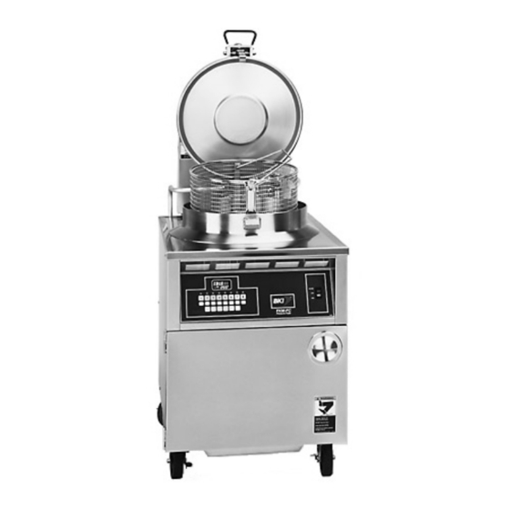
Page 4: Introduction
Electric Pressure Fryer The FKM Pressure Fryer is compact, attractive and functional in design. It is constructed of a stainless steel fryer pot for cleaning ease. Exclusive BKI patented features and safety devices offer flexibility, efficiency and reliability plus PERFECTION IN PRESSURE FRYING! The BKI name and trademark on this unit assures you of the finest in design and engineering -- that it has been built with care and dedication -- using the best materials available. -
Page 5: Specific Precautions
Electric Pressure Fryer Specific Precautions Lids for FKM Pressure Fryers manufactured prior to May 27, 1980 (or units with serial numbers lower than 3613) could be manually opened while under pressure resulting in serious injury or death. If you have one of these units, please contact the BKI Technical Services Department toll-free at 1-800-927-6887 for urgent update information. -
Page 6: Safe Work Practices
Make sure to keep the area around your fryer clear of any obstacles. Serious injury can occur if you trip or fall near the fryer. You could be burned by hot shortening that splashes out of the fryer or by falling against the hot metal of the fryer. - Page 7 Keep Away From The Vent Hot steam escapes from the vent continuously when you are using your fryer. You could be burned if you get too close to the vent. Seal The Safety Valve Properly To seal the safety valve, lift the arm on the side of the valve. Then release it.
- Page 8 After the pressure gauge is at zero, wait 5 seconds. Then loosen the spin handle slowly to open the lid of the fryer. By doing this, the steam will escape slowly and there is less change of being burned.
- Page 9 Electric Pressure Fryer Keep Safety Labels Clean and in Good Condition Do not remove or cover any safety labels on your equipment. Keep all safety labels clean and in good condition. Replace any damaged or missing safety labels. Refer to the Safety Labels section for illustration and location of safety labels on this unit.
-
Page 10: Safety Labels
Electric Pressure Fryer Introduction Safety Labels... - Page 11 Electric Pressure Fryer Introduction...
-
Page 12: Installation
Electric Pressure Fryer Installation Installation For installation information refer to Electric Pressure Fryer, MODELS FKM, FKM-F, & FKM-FC, Installation and Operation Manual LI0102. -
Page 13: Operation
Electric Pressure Fryer Operation Operation Controls and Indicators Refer to the figure and table below for an explanation of the fryer’s controls and indicators. - Page 14 Electric Pressure Fryer Item # Description Spin Handle Pop Safety Valve lever Pressure Gauge Computer Rocker Switch Thermostat Knob Thermostat Light Digital Timer LED indicator TIME SELECT (2 arrow buttons) START/STOP button Function Used to tighten the lid to the pot once it is latched.
- Page 15 Electric Pressure Fryer Item # Description ALARM button A, B, C, D preset buttons Beeper Display High Limit Reset Switch Drain Lever Fill Lever Rinse Hose Connector Pump Motor Reset Switch Function This button allows the user to set an elapsed time at which the internal alarm will sound during a cycle.
-
Page 16: Care Of The Shortening
“0” button on the FKM-FC model. On Models FKM and FKM-F, set the thermostat to 150º F. 7. Shortening changes are determined by the quantity and type of food prepared. Excessive boiling and foaming are definite signs of shortening breakdown. - Page 17 4. Set the thermostat to the desired cook temperature. The temperature light will go on. When the temperature is reached, the light will go off. The light will continue to cycle on and off as the fryer maintains the set temperature.
-
Page 18: Cooking (Fkm And Fkm-F)
8. Activate the timer by pressing the START/STOP button on the digital timer. The timer will begin the count down. 9. At the end of the frying cycle, the digital timer beeper will sound and the fryer will automatically release pressure into the baffle box. Press the START/STOP button. -
Page 19: Fkm-Fc Operation
14. Remember to filter the shortening at least every third frying cycle load. Refer to the procedure in this manual. Also filter the shortening and clean the fryer at the end of each day. If you do not plan to use the fryer for an hour or more, turn the thermostat down to 150 and close the lid. - Page 20 Electric Pressure Fryer Table 1. System Programming Procedure STEP ACTION Press the FILTER/OFF/FRY switch to FRY. Press PROG on the keypad. Input 1712 and ENTER. Press ENTER. Press TOGGLE/CLEAR until the desired option is displayed. Press ENTER. Press TOGGLE/CLEAR until the desired option is displayed.
-
Page 21: Product Programming
Electric Pressure Fryer Operation Product Programming Use the following figure and table to set a maximum of eight product programs. The product programs must be set before cooking can begin. Figure 2. Product Programming Sequence... - Page 22 The FLEX TIME option will allow the fryer to recover from temperature loss. PROGRAM TEMPCOM1 X refers to the temperature compensation option selected.
- Page 23 Electric Pressure Fryer STEP ACTION Press TOGGLE/CLEAR until the desired option is displayed. Repeat steps 5-12 when programming stages 2, 3, 4 and 5 for Electric and Gas appliance types. Repeat steps 5-10 when programming stages 2, 3, 4 and 5 for an ALF appliance type.
-
Page 24: Start-Up (Fkm-Fc)
Do not use any shortening other than what is specified in this manual and do not overfill the fryer pot. The FKM-FC fryer has a maximum temperature setting of 390º F (200º C). Do not use oil/shortening with a flashpoint less than 554º F (290º C) Use only high-quality shortening that has low moisture content, a high smoke point and no additives. - Page 25 For your safety, the lid will not unlock, even at the end of the cook cycle, until the pressure has been fully released.
-
Page 26: Maintenance
Electric Pressure Fryer Maintenance Maintenance For maintenance information refer to Electric Pressure Fryer, MODELS FKM, FKM-F, & FKM-FC, Installation and Operation Manual LI0102. -
Page 27: Replacement Parts
Assemblies Description DEAD WEIGHT ASSEMBLY DOOR ASSEMBLY DRAIN/MOTOR/PIPING ASSEMBLY DRAIN VALVE & PLUGS DOMESTIC FRONT PANEL FKM/FKM-F EUROPEAN FRONT PANEL FKM/FKM-F FRONT PANEL FKM-FC LID/TOP ASSEMBLY OIL VAT ASSEMBLY QUICK DISCONNECT ASSEMBLY DOMESTIC REAR PANEL FKM/FKM-F... - Page 28 ELL, STREET 1/4 90 DEG CP COUPLING, BRASS 1/4 FITTING, COMPRESSION ¾” BUSHING, C110JO 3/4 X 1/2 CP NIPPLE, 1/4 X 1 1/2 SS 304 COVER, DEAD WEIGHT VALVE FKM BODY, DEAD WEIGHT VALVE FKM WEIGHT, VALVE FKM 12# GAUGE, PRESSURE 30 PSI Replacement Parts...
- Page 29 WFKMA178 N0153 H0009 Figure 4. Door Assembly Table 4. Door Assembly Parts THREAD INSERT 10-24 STEEL BRACKET, BRUSH HOLDER FKM, LPF,LGF HINGE, LH PIN HALF DECAL, SMALL BRUSH/ DECAL, NOTICE LOST MANUAL DECAL, SAFETY INSTR FRYERS DECAL, SLIPPING ADMONITIONS DECAL, INSTR & SAFETY MANUAL...
- Page 30 Electric Pressure Fryer Replacement Parts Figure 5. Drain/Motor/Piping Assembly...
- Page 31 BUSHING, BLK 1/2 HEYCO SNAP SWITCH,ACT. COVER FKMA247 SWITCH, MICRO BZ-2RW822-A2 HANDLE SUPPORT PLATE DECAL, FKM-F DRAIN HNDL PLATE SCREW, 6-32 X 1 SL RD HD MS HANDLE, DRAIN VALVE FKM BLF COVER, DRAIN HANDLE RED SCREW, 8 X 1/2 PHIL PAN HEAD...
- Page 32 Electric Pressure Fryer ITEM # PART # MB19101000 FT0243 Figure 6. Drain Valve & Plugs Table 6. Drain Valve & Plugs Parts DRAIN VALVE REPLACEMENT PLUG, 3/8" SQ HEAD PIPE Replacement Parts DESCRIPTION...
- Page 33 Electric Pressure Fryer Figure 7. Domestic/European Front Panel FKM/FKM-F Table 7. Domestic/European Front Panel FKM/FKM-F Parts ITEM # PART # N0522 S0104 TI0032 PL0004 T0075 K0040 DESCRIPTION DECAL, CTL PNL FKM FKMF SWITCH, RKR DPDT 15A 250V LAMP TIMER, 230V DIGITAL 4 BUTTON...
- Page 34 Electric Pressure Fryer Table 8. Front Panel FKM-FC Domestic Parts ITEM # PART # N0524 S0104 CP0039 Figure 8. Front Panel FKM-FC DECAL,CTL PNL FKMFC SWITCH, RKR DPDT 15A 250V LAMP CONTROLLER, VFD LESS HARNESS Replacement Parts DESCRIPTION...
- Page 35 Electric Pressure Fryer Replacement Parts Figure 9. Lid/Top (sheet 1 of 4)
- Page 36 Electric Pressure Fryer Replacement Parts Figure 9. Lid/Top (Sheet 2 of 4)
- Page 37 Electric Pressure Fryer Replacement Parts Figure 9. Lid/Top (Sheet 3 of 4)
- Page 38 Electric Pressure Fryer Replacement Parts Figure 9. Lid/Top (Sheet 4 of 4)
- Page 39 SPRING, HOOK LGF LPF FKM SCREW, 1/4-20 X 1/2 FLAT HD SCREW, 1/4-20 X 1/2 PHIL RD HD BUSHING, BRONZE 1" HANDLE SIDE FOR H0155 FKM LPF LGF WASHER, 5/16 LOCK ZINC PLTD WASHER, 1/4 INT LOCK PLUG, HOLE 3/8" SHORT PRONG...
- Page 40 Electric Pressure Fryer Replacement Parts Figure 10. Oil Vat Assembly...
- Page 41 FILTER VAT TUBE WELD, BLF FILTER SCREEN FITTING SPOTWELD FILTER SCREEN, TOP FILTER SCREEN, INTERCEPTOR FILTER SCREEN, BOTTOM NUT SCREEN RETAINING FKM-F & FILTER VAT WELD QUIK DISC COVER, FILTER VAT DECAL, VAT COVER SAFETY WARN CRUMB BASKET WELD, LG VAT ASSY Figure 11.
- Page 42 Electric Pressure Fryer Figure 12. Domestic/European Rear Panel FKM/FKM-F Table 12. Domestic/European Rear Panel FKM/FKM-F Parts ITEM # PART # T0036 TB0064 TB0065 TB0068 TB0069 R0148 F0158 F0097 R0134 F0154 F0342 FH0001 FT0080 FT0277 DESCRIPTION THERMOSTAT, HI LIMIT 540 DEG...
- Page 43 F0158 F0342 FH0001 FT0080 FT0277 Figure 13. Rear Panel FKM-FC Table 13. Rear Panel FKM-FC Parts THERMOSTAT, HI LIMIT 540 DEG RELAY, 3 POLE 42CF35AG TERM BLOCK 4 CONDUCTOR CTR TERM BLOCK 4 CONDUCTOR W/MTG FOOT TERM BLOCK END PLATE...
- Page 44 Electric Pressure Fryer Table 14. Solenoid Valve Assembly Parts ITEM # PART # FT0249 FT0396 SV0001 FT0563 Figure 14. Solenoid Valve Assembly CONNECTOR, 3/8 STR FLEX LIQUIDTITE PIPE, DEAD WT TO BAFFLE BOX VALVE, SOLENOID HV-214-761-2 240V FITTING, COMPRESSION ¾”...
-
Page 45: Accessories
Electric Pressure Fryer Accessories Description BASKET, LARGE FKM BAIL HANDLE BRUSH, DRAIN (LONG WHITE) BRUSH, L TIPPED 40152 BRUSH, LONG #5702 BRUSH, POT SCRUBBER, WHITE BRUSH, SHORT #6175 CORD SET, FKM-FC 7' FILTER HOSE, FEMALE SOCKET FILTER VAT DOLLY FKM-F INSULATED MITT 13"... -
Page 46: Components
COLLAR, 1/2" SET BRIGHT CONDENSATION PAN WELDMENT DRAIN PIPE, CONDENSATE FKM FILTER, FKM-F 13.5 X 20.5 OUTLET BOX, (ON FKM ONLY FOR POWERING FKF) PROBE ASSEMBLY KIT, COMPUTER SEMI AUTOMATIC HOSE ASSEMBLY (FKM only) SIDE CABINET, L&R FKM/DNF SLIDE, UHMW U-SHAPE .5 X 1/8ID STRIKER PLATE (DOOR CATCH) SWITCH, ACT. - Page 47 Electric Pressure Fryer Replacement Parts...
-
Page 48: Wiring Diagrams
Electric Pressure Fryer Wiring Diagrams Wiring Diagrams Figure 17. FKM-F 208V/220V/240... - Page 49 Electric Pressure Fryer Wiring Diagrams Figure 18. FKM-F 220V/380V, 230V/400V, 240V/415V...
- Page 50 Electric Pressure Fryer Wiring Diagrams Figure 19. FKM-FC 208V/220V/240V (Sheet 1 of 4)
- Page 51 Electric Pressure Fryer Wiring Diagrams Figure 19. FKM-FC 208V/220V/240V (Sheet 2 of 4)
- Page 52 Electric Pressure Fryer Wiring Diagrams Figure 19. FKM-FC 208V/220V/240V (Sheet 3 of 4)
- Page 53 Electric Pressure Fryer Wiring Diagrams Figure 19. FKM-FC 208V/220V/240V (Sheet 4 of 4)
- Page 54 Electric Pressure Fryer Wiring Diagrams Figure 20. FKM-FC 220V/380V, 230V/400V, 240V/415V (Sheet 1 of 4)
- Page 55 Electric Pressure Fryer Wiring Diagrams Figure 20. FKM-FC 220V/380V, 230V/400V, 240V/415V (Sheet 2 of 4)
- Page 56 Electric Pressure Fryer Wiring Diagrams Figure 20. FKM-FC 220V/380V, 230V/400V, 240V/415V (Sheet 3 of 4)
- Page 57 Electric Pressure Fryer Wiring Diagrams Figure 20. FKM-FC 220V/380V, 230V/400V, 240V/415V (Sheet 4 of 4)
-
Page 58: Notes
Electric Pressure Fryer Notes Notes... - Page 59 Electric Pressure Fryer...
- Page 60 P.O. Box 80400, Simpsonville, S.C. 29680-0400, USA http://www.bkideas.com Made and printed in the U.S.A LI0192/0808...
Need help?
Do you have a question about the FKM and is the answer not in the manual?
Questions and answers