Solid State Logic XL-Desk Owner's Manual
The smart dumb analogue console
Hide thumbs
Also See for XL-Desk:
- Installation instructions manual (16 pages) ,
- Owner's manual (40 pages)

Subscribe to Our Youtube Channel
Related Manuals for Solid State Logic XL-Desk


Summary of Contents for Solid State Logic XL-Desk
- Page 1 XL-Desk The smart dumb analogue console Owner’s Manual XL-Desk This is SSL.
- Page 2 Document History 82BMLM01A Initial Release September 2014 Page B XL-Desk – Owner’s Manual...
-
Page 3: Table Of Contents
Power Connection Thermal Considerations Rear Panel Connections Connector Summary D-sub to XLR Breakout Leads 3. Studio Integration Connectivity Example Using XL-Desk Without a Patchbay Using XL-Desk With a Patchbay Patchbay Guidelines Line Level Input/Outputs Mic Inputs 4. Tutorials The VHD preamplifier... - Page 4 Mon Select Mon Source Foldback Bargraph Metering How to track with XL-Desk Example 1 - Recording a small ensemble in a ‘split’ console style. Example 2 - Recording a Full Band and Monitoring Back Via Stems Creating Headphone Mixes for Tracking...
-
Page 5: Introduction
1. Introduction About This User Guide Congratulations on purchasing your Solid State Logic XL-Desk. This User Guide aims to provide you with all the necessary information to operate the console. The Guide is arranged into the following sections: Introduction An overview of XL-Desk’s features. -
Page 6: Overview
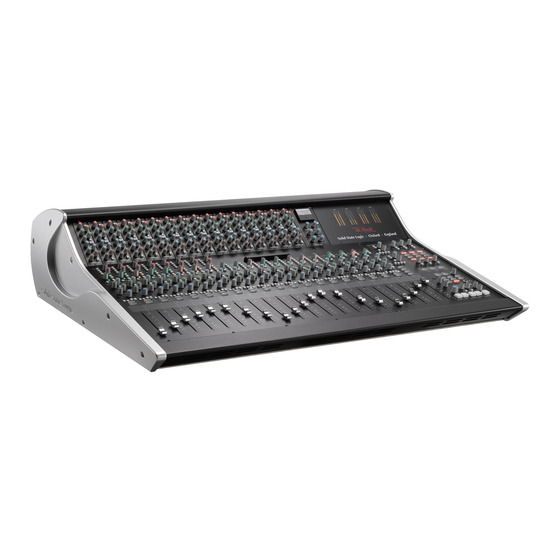
SSL console products have. XL-Desk is in many ways a traditional 24 into 8 analogue console but it packs in an incredible collection of features. It has 20 channel strips: 16 dual input mono (switchable between main input or DAW return) and 4 stereo channels. The first eight channels have VHD mic pre’s. -
Page 7: Workflow
. With 2 insert points on each mono channel you can mix and match rackmount and 500-series processors to make the XL-Desk the hub of your hybrid studio world! Connect your XL-Desk to a patchbay for ultimate flexibility, and use the direct outs from every channel and Bus to print files back into your DAW for easy mix revisions. - Page 8 Mix Insert send for the 4 stereo mix busses MIX A B C D RETURN Mix Insert return for the 4 stereo mix busses MIX A B C D OUT Stereo mix bus outputs AJ and CJ Top secret! Page 4 XL-Desk – Owner’s Manual...
-
Page 9: Installation
When connecting directly to external equipment – amplifiers, effects units, meters etc. – adapter leads that convert the console’s DB25 female connectors into 8 x XLRs are likely to be useful. Refer to the table on page 4 for notes on where these adapter leads might be required. XL-Desk – Owner’s Manual Page 5... - Page 10 Direct Outs Mix Bus Outputs Stereo return Outputs Headphones MP3 Player Foldback Outputs A & B Listen Mic Insert Insert Cue/Aux Stereo Sends Returns Sends Return Input Live Room Outboard FX Outboard Rack Gear (Reverb/Delays) Page 6 XL-Desk – Owner’s Manual...
-
Page 11: Studio Integration
ITHOUT A ATCHBAy If using XL-Desk without an external patchbay, it is necessary to use the 4 included short D-Sub cables (shipped with XL- Desk) to link the following connections on the rear: Send from channel goes to 500 rack slot input... -
Page 12: Using Xl-Desk With A Patchbay
ITH A ATCHBAy For ultimate flexibility, XL-Desk can connect to a standard 25-way D-Sub patchbay. One of the advantages of using a patchbay is that it will allow patching between 500 rack modules. The image below is a suggested layout for console connection using 4 patchrows. -
Page 13: Tutorials
HANNeLS Input Each channel of XL-Desk has two inputs, switchable by pressing the DAW button. The primary input on channels 1-8 is the VHD microphone preamplifier. This is labelled as MIC INPUT 1-8 on the rear panel. Pressing the DAW button will instead source the line-level input labelled DAW INPUT 1-8 on the rear panel. -
Page 14: Trim
INSERT SEND/RETURN. CHOP Makes the direct channel output post-fader, instead of pre-fader POST * Please refer to the 500-series Rack section of this chapter for more information regarding signal flow to and from the rack. Page 10 XL-Desk – Owner’s Manual... -
Page 15: Stereo Cue And Mono Auxes
Stereo Cue and Mono Auxes XL-Desk has a STeReO CUe bus which can be sent to using the green level pot and panned with the blue pot. The Stereo Cue is switchable between pre or post-fader, on a per-channel basis using the POST button. During tracking, the Stereo Cue could be used for an artist’s headphone mix. -
Page 16: Stereo Channels
XL-Desk provides 4 stereo input channels located immediately to the left of the Mix A master bus fader. The stereo channels on XL-Desk differ from the mono in the following ways: • Stereo channels have one stereo input per strip •... -
Page 17: 500-Series Rack
Slots 1–16 Built into the penthouse of XL-Desk is a 500-series rack. This rack is a 16 + 2 slot design. The image shows the rack filled with SSL modules – but of course, this could be a selection of 500-series modules from other manufacturers. -
Page 18: Stereo Sidechain Link For Odd/Even Pairs
Using the 500-series Rack With or Without a Patchbay The rear panel of XL-Desk allows access to the inputs and outputs of the 500-series rack. These D-Subs are labelled: 500 SLOT IN 1-8, 500 SLOT IN 9-16, 500 SLOT OUT 1-8 and 500 SLOT OUT 9-16. -
Page 19: Bus Compressor
Bus Compressor Included with every XL-Desk is the legendary SSL Bus Compressor for 500-series. It is a simple unit with a simple purpose; it makes complete mixes sound bigger, with more power, punch and drive. It brings cohesion and strength to your mix without compromising clarity. The updated design now includes a notched high-pass filter in the sidechain. -
Page 20: Centre Section
Mix B, Mix C, Mix D Master Controls 3 of the XL-Desk’s 4 stereo mix busses are controlled in this section. The controls that apply to Mix B, C and D are identical. Mix Busses B, C and D do not have dedicated 500-series rack slots associated with them. However, by pressing the 500 button, XL-Desk allows each Mix Bus to ‘steal’... -
Page 21: Mix A Master Controls
SIP – XL-Desk’s default soloing mode. When a solo is made, all other channels are CUT. AFL – Press the AFL button to switch XL-Desk into AFL solo mode. When a solo is made, the signal(s) is sent to the AFL bus. The monitoring section will automatically source the AFL bus if a solo is made in this mode. -
Page 22: Monitoring Section
AFL control - Sets the level of the AFL bus. Mon Select XL-Desk allows up to three pairs of stereo monitor speakers to be connected, as well as a dedicated sub speaker. MONO sends the summed Left and Right Stereo signal to both monitor speakers. -
Page 23: Foldback
LISTeN allows the engineer to monitor the incoming Listen microphone signal. The listen microphone is typically set up somewhere near the middle of the live room. (The LISTEN INPUT to XL-Desk is found on the rear panel as a female XLR connection.) The black TALK control sets the gain of the in-built front panel talkback microphone. -
Page 24: How To Track With Xl-Desk
OW TO TRACK WITH There are many different ways in which XL-Desk can be used to record music. If you’re looking for some “tried and tested” industry techniques from the pro’s on how best to operate this desk, then please read on. - Page 25 8) In your DAW record arm the 8 channels for recording. Route the outputs of these tracks into DAW INPUT 9-16 on XL-Desk. 9) Press the DAW button for channels 9-16 and you will see signal coming into the desk.
-
Page 26: Example 2 - Recording A Full Band And Monitoring Back Via Stems
MIC INPUT 1 - 8 1) Plug the first 8 microphones into MIC INPUT 1-8 of XL-Desk (all the drums). (Using the DB25 to 8 XLR female interface lead.) LINE INPUT 9 - 16 DAW INPUT 1 - 8 2) Use external preamplifiers for inputs 9 -16. - Page 27 10) Route the sub-groups out of the DAW into the stereo channels of XL-Desk. Route the click track into the final stereo input on XL-Desk and press the MONO button. Route these channels to Mix Bus A using the A routing button above the CUT button.
-
Page 28: Creating Headphone Mixes For Tracking
Creating Headphone Mixes for Tracking Here is a useful example of how to create headphone mixes during tracking. XL-Desk provides two foldback circuits. Foldback A is fed by the STEREO CUE bus and talkback can be injected using the TALK A button. Foldback B is fed by the Headphone AUX 1 bus and talkback can be injected using the TALK B button. -
Page 29: Using 500-Series Rack Slots 9-16 With Microphone Preamplifiers
Using 500-series Rack Slots 9-16 with Microphone Preamplifiers You may already own 500-series microphone preamplifier modules and ‘500’ Preamplifiers wish to use these with XL-Desk. You can fill 500-series rack slots 9-16 with microphone preamplifier modules and use them by doing the following: 1) Plug the microphone(s) into the microphone preamplifier module(s). - Page 30 This page is intentionally bank. (It’s a tradition) Page 26 XL-Desk – Owner’s Manual...
-
Page 31: Configuration
3) Press the MINI 1 button again to exit the setup mode and return to normal operation. To adjust MINI 2, repeat the process but replace MINI 1 button presses with MINI 2 button presses. XL-Desk – Owner’s Manual Page 27... -
Page 32: Option Dip Switches
Option DIP Switches The rear panel of XL-Desk has 12 DIP switches that can be used to set various functions of the desk. As you face the rear panel of XL-Desk, the left-hand block of 6 DIP switches are options 1-6, the second block of 1-6 are options 7-12. -
Page 33: Appendices
6. Appendices A – S PPeNDIX IGNAL LOCK IAGRAM XL-Desk – Owner’s Manual Page 29... -
Page 34: Appendixb - Console Dimensions
B – C PPeNDIX ONSOLe DIMeNSIONS Page 30 XL-Desk – Owner’s Manual... -
Page 35: Appendix C - Connector Pinouts
0.25” Jack Socket Connector Type: 3.5mm Stereo Skt Description Description Signal Left Signal Left Image shows a male connector viewed from the wiring side Ring Signal Right Ring Signal Right Sleeve 0V (Chassis) Sleeve 0V (Chassis) XL-Desk – Owner’s Manual Page 31... -
Page 36: Appendix D - 500-Series Rack Specifications
- - - Input +4dB Hot Input +4dB Hot Gain Adjustment - - - +16VDC Supply +16VDC Supply Power Ground – 0V ref Power Ground – 0V ref -16VDC Supply -16VDC Supply +48VDC Phantom +48VDC Phantom Page 32 XL-Desk – Owner’s Manual... -
Page 37: Appendix E - Technical & Environmental Specifications
In such cases Solid State Logic will return the unit in a suitable box, which you will be charged for. • Do not include the power cable, manual or any other items – Solid State Logic can not guarantee to return them to you. XL-Desk – Owner’s Manual... -
Page 38: Appendix F - Hardware
OTeS Page 34 XL-Desk – Owner’s Manual... -
Page 39: Notes
OTeS XL-Desk – Owner’s Manual Page 35... - Page 40 No part of this publication may be reproduced in any form or by any means, whether mechanical or electronic, without the written permission of Solid State Logic, Oxford, OX5 1RU, England As research and development is a continual process, Solid State Logic reserves the right to change the features and specifications described herein without notice or obligation.
Need help?
Do you have a question about the XL-Desk and is the answer not in the manual?
Questions and answers