Table of Contents
Advertisement
Quick Links
2595H
7/29/09
10:15 AM
Page 1
®
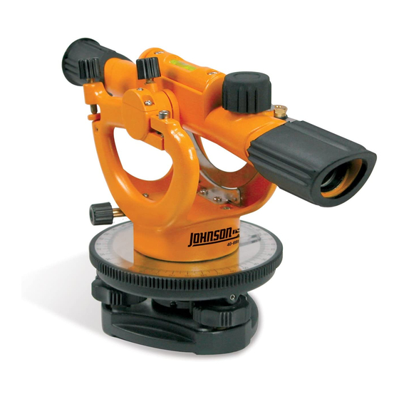
22X Builder's Transit Level
Model No. 40-6910
Instruction Manual
Congratulations on your choice of this 22X Builder's Transit Level. We
suggest you read this instruction manual thoroughly before using
the instrument. Save this instruction manual for future use.
©2009 Johnson Level & Tool Rev.1
1
Advertisement
Table of Contents

Related Manuals for AccuLine 40-6910


Summary of Contents for AccuLine 40-6910
- Page 1 10:15 AM Page 1 ® 22X Builder’s Transit Level Model No. 40-6910 Instruction Manual Congratulations on your choice of this 22X Builder’s Transit Level. We suggest you read this instruction manual thoroughly before using the instrument. Save this instruction manual for future use.
-
Page 2: Table Of Contents
2595H 7/29/09 10:15 AM Page 2 Table of Contents 1. Kit Contents Technical Specifications 2. Features and Functions Care and Handling 3. Location of Parts/Components Product Warranty 4. Operating Instructions Product Registration 5. Calibration 10. Accessories 1. Kit Contents Description Qty. -
Page 3: Location Of Parts/Components
2595H 7/29/09 10:15 AM Page 3 3. Location of Part/Components Focusing knob Leveling Vial Lock Lever Vertical arc Eyepiece Vertical vernier Horizontal graduated circle Horizontal vernier Vertical tangent knob Vertical lock knob Horizontal Telescope tangent knob objective lens Leveling screw Base ©2009 Johnson Level &... -
Page 4: Operating Instructions
2595H 7/29/09 10:15 AM Page 4 4. Operating Instructions IMPORTANT: It is the responsibility of the user to verify the calibration of the instrument before each use. Set-Up the instrument on the tripod When setting up the tripod, make sure the three tripod points are firmly into the ground and the top of the tripod head is as level as possible. - Page 5 2595H 7/29/09 10:15 AM Page 5 Keep about half the length engaged. When the bubble is centered in posi- tion #1, turn the instrument and observe the vial in position #2. Now cen- ter the bubble in position #2 using only screw C. The instrument should now be leveled, but to be certain, double-check.
-
Page 6: Calibration
2595H 7/29/09 10:15 AM Page 6 In the illustration to the right, the index has passed the 44 degree line but has not gone as far as the 45 degree line. In this case, the third vernier line from the index is lined up with one of the lines on the circle. - Page 7 2595H 7/29/09 10:15 AM Page 7 With an adjusting screw “A” facing to the right Bubble level of the bubble and with telescope directly in screws line with two of the three leveling screws, note to which side the bubble is off. If to the left, loosen screw “B”...
- Page 8 2595H 7/29/09 10:15 AM Page 8 5.3 Instrument accuracy adjustment If the error is more than 3/16” at 100’, it is necessary to adjust the instrument. Eyepiece tube When adjusting the instrument: 1. Remove rubber cover to expose the two Eyepiece seat Set Screws calibration set screws.
- Page 9 2595H 7/29/09 10:15 AM Page 9 5.5 Determining difference in elevation Measuring a difference in elevation from one set-up To find the difference of elevation between two points which can be observed from one position, set up and level your instrument about midway between these points.
- Page 10 2595H 7/29/09 10:15 AM Page 10 5.6 Measure the difference in elevation requiring more than one set-up If two points are either too far apart or at too great a difference of elevation to be observed from one set-up, the procedure shown below is recommended.
- Page 11 2595H 7/29/09 10:15 AM Page 11 5.7 Stadia Distance Measuring Distance measuring can be done using the stadia hairs of the reticle. The distance between the upper stadia hair and the lower stadia hair is set at a 1:100 ration. So if the difference is 1 foot, the person holding the grade rod is 100 feet away from the instrument.
- Page 12 2595H 7/29/09 10:15 AM Page 12 instrument over point F in accordance with previous instructions. Rotate the instrument until point E is nearly in line with the vertical crosshair. Turn tangent screw until vertical crosshair is on point E. By hand set the horizontal circle to read zero.
-
Page 13: Technical Specifications
2595H 7/29/09 10:15 AM Page 13 6. Technical Specifications Telescope Erect Magnification Leveling accuracy ± 3/16"/100 ft. (±5mm/30m) Working range Up to 200’ (60m) Minimum focus 4’ (1.2m) Clear objective aperture 22mm Field of view ± 2’/100 ft. (±0.6m/30m) Number of lenses Level vial 4’... -
Page 14: Care And Handling
Do not return this product to the store/retailer or place of purchase. Required repair/calibration must be done by an authorized AccuLine Pro® service center or Johnson Level & Tool's limited warranty, if applicable, will be void and there will be NO WARRANTY. -
Page 15: Product Registration
2595H 7/29/09 10:15 AM Page 15 NOTE: The user is responsible for the proper use and care of the product. It is the responsibility of the user to verify the calibration of the instrument before each use. For further assistance, or if you experience problems with this product that are not addressed in this instruction manual, please contact our Customer Service Department. -
Page 16: Accessories
10. Accessories AccuLine Pro® accessories are available for purchase through authorized AccuLine Pro dealers. Use of non-AccuLine Pro accessories will void any applicable limited warranty and there will be NO WARRANTY. If you need any assistance in locating any accessories, please contact our Customer Service Department.
Need help?
Do you have a question about the 40-6910 and is the answer not in the manual?
Questions and answers