Table of Contents
Advertisement
Quick Links
2260H
6/4/09
11:42 AM
Page 1
®
Manual-Leveling Rotary Laser Level
Model Nos. 40-6502 and 40-6512
Instruction Manual
Congratulations on your choice of this Manual-Leveling Rotary Laser
Level. We suggest you read this instruction manual thoroughly before
using the instrument. Save this instruction manual for future use.
This is a Class IIIa laser tool and is manufactured to comply
with CFR 21, parts 1040.10 and 1040.11 as well as international
safety rule IEC 285.
©2009 Johnson Level & Tool
1
Advertisement
Table of Contents

Subscribe to Our Youtube Channel
Related Manuals for AccuLine 40-6502


Summary of Contents for AccuLine 40-6502
- Page 1 11:42 AM Page 1 ® Manual-Leveling Rotary Laser Level Model Nos. 40-6502 and 40-6512 Instruction Manual Congratulations on your choice of this Manual-Leveling Rotary Laser Level. We suggest you read this instruction manual thoroughly before using the instrument. Save this instruction manual for future use.
-
Page 2: Table Of Contents
12. Product Warranty 5. Location of Parts/Components 13. Product Registration 6. Operating Instructions 14. Accessories 7. Using the Product 1. Kit Contents For Model No. 40-6502 Description Qty. Manual-Leveling Rotary Laser Level “AA” Alkaline Batteries Tinted Glasses Instruction Manual with Warranty Card Soft-sided Carrying Case For Model No. -
Page 3: Features And Functions
2260H 6/4/09 11:42 AM Page 3 2. Features and Functions • Emits a horizontal laser plane. • Emits a vertical laser plane with simultaneous 90º split beam. • Large and small scan modes achieve a chalk line. • Scan line can be moved clockwise or counter-clockwise. •... - Page 4 2260H 6/4/09 11:42 AM Page 4 ATTENTION IMPORTANT • Read all instructions prior to operating this laser tool. Do not remove any labels from tool. • Do not stare directly at the laser beam. • Do not project the laser beam directly into the eyes of others. •...
-
Page 5: Location/Content
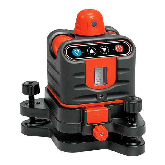
2260H 6/4/09 11:42 AM Page 5 4. Location/Content of Warning Labels ©2009 Johnson Level & Tool... - Page 6 2260H 6/4/09 11:42 AM Page 6 5. Location of Part/Components 90º Split Beam Rotating beam Output Window output window Keypad Z-level Vial Z-vial calibrating hole Base unlock/lock DC 6V outlet knob Y-vial leveling knob X-level Vial Y-level Vial X-vial leveling knob 5/8”...
-
Page 7: Operating Instructions
2260H 6/4/09 11:42 AM Page 7 6. Operating Instructions IMPORTANT: It is the responsibility of the user to verify the calibration of the instrument before each use. 1. Power ON/OFF 2. Power LED 3. Decrease rotation speed/rotate scan clockwise 4. Increase rotation speed/rotate scan counterclockwise 5. - Page 8 2260H 6/4/09 11:42 AM Page 8 DOT: Laser stops rotating and projects a DOT (scan mode LED (5) blinks). 3. UP and Down Keys: In the rotation mode: Press rotation speed increases (Note: when turning the power on, the laser is in its highest rotation speed) Press rotation speed decreases In the scan mode:...
-
Page 9: Using The Product
2260H 6/4/09 11:42 AM Page 9 7. Using the Product Connecting the Laser to its Base Horizontal Base Unlock/Lock Knob Vertical Position the two slots on the laser into the base, tighten the locking knob to secure the base to the laser. The laser can now be secured to a tripod. - Page 10 2260H 6/4/09 11:42 AM Page 10 4. Put the battery cover back into place (rotate the battery compart- ment knob to the lock position). Battery compartment Base Unlock/Lock Knob Level Vial Adjustment: To adjust the laser to center the vial. Z-level Vial X-level Vial X-vial leveling...
- Page 11 2260H 6/4/09 11:42 AM Page 11 Vertical Usage 1. Put 4 “AA” alkaline batteries in the unit. 2. As shown in figure on previous page, place the laser on a flat surface or 5/8” - 11 tripod 3. Adjust the vial leveling knobs to center the bubble inside the Z-vial.
- Page 12 2260H 6/4/09 11:42 AM Page 12 2. Components (a) Structure 1. Holding Cord 2. Signal Indicator 3. Horn 4. Horizontal Vial 5. Detecting Window 6. Reference Front Marker 7. Power Key 8. Back Reference Marker 9. Connection Port 10. Battery Door (b) Display When first turning the detector on, the middle signal indicator turns red first and then turns green.
- Page 13 2260H 6/4/09 11:42 AM Page 13 Note: Take the batteries out when the unit is not in use for a long time. 4. Detecting Methods 1. This unit can detect a red rotating laser beam. 2. Press the Power Key once , the middle signal indicator will quickly turn red first and then turns green.
- Page 14 2260H 6/4/09 11:42 AM Page 14 Horizontal Vial 2. Keep the detecting window facing the rotating laser. 3. Keep the detector still while detecting the laser beam 4. When the laser beam is centered, mark at the front reference marker. 5.
- Page 15 2260H 6/4/09 11:42 AM Page 15 • Connecting to the grade rod The top of the bracket should be level with the back reference marker line 6. Maintenance • When you are done using the detector, return it to its case. •...
-
Page 16: Self-Check And Calibration
2260H 6/4/09 11:42 AM Page 16 8. Self-Check and Calibration IMPORTANT: It is the responsibility of the user to verify the calibration of the instrument before each use. X and Y-direction Vial Self-Check and Calibration L (50’) 1. As shown in the figure above, place the laser at position L 50’ away from the wall (start with the X-vial facing the wall). - Page 17 2260H 6/4/09 11:42 AM Page 17 Use a 2.5 Metric Hex Key to remove the X vial screw in the X level vial calibration aperture. Then using the 2.5 Metric Hex Key, adjust the vial bubble to the middle of the vial as shown below.
-
Page 18: Technical Specifications
2260H 6/4/09 11:42 AM Page 18 9. Technical Specifications Laser Wavelength 635nm±10nm Laser Classification Class IIIa ≤5mW Maximum Power Output Accuracy ±1/4"/100 ft. (±2mm/10m) Interior Range Up to 200 ft. (60m) diameter depending upon light conditions Exterior Range Up to 800 ft. (240m) diameter with detector Power Supply 4 “AA”... -
Page 19: Application Demonstrations
2260H 6/4/09 11:42 AM Page 19 10. Application Demonstrations Ceiling installation Anti-static flooring installation Window installation Baseboard installation Hanging pictures Dormer installation ©2009 Johnson Level & Tool... -
Page 20: Care And Handling
2260H 6/4/09 11:42 AM Page 20 11. Care and Handling This laser unit is a precision tool that must be handled with care. • Avoid exposing unit to shock vibrations and extreme temperatures. • Before moving or transporting the unit, make sure that the unit •... -
Page 21: Product Warranty
2260H 6/4/09 11:42 AM Page 21 Customer Service Department to obtain a Return Material Authorization (RMA) number for return to an authorized service center. Proof of purchase is required. NOTE: The user is responsible for the proper use and care of the product. -
Page 22: Accessories
2260H 6/4/09 11:42 AM Page 22 14. Accessories AccuLine Pro ® accessories are available for purchase through authorized AccuLine Pro dealers. Use of non-AccuLine Pro accessories will void any applicable limited warranty and there will be NO WARRANTY. If you need any assistance in locating any accessories, please contact our Customer Service Department. -
Page 23: Johnson Level & Tool
2260H 6/4/09 11:42 AM Page 23 ©2007 Johnson Level & Tool... - Page 24 2260H 6/4/09 11:42 AM Page 24 ©2007 Johnson Level & Tool...
Need help?
Do you have a question about the 40-6502 and is the answer not in the manual?
Questions and answers