Advertisement
Quick Links
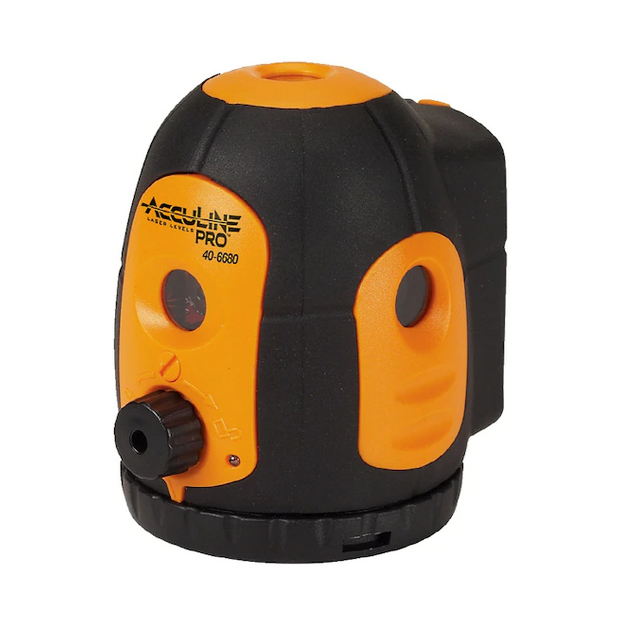
40-6680 5 Beam Laser Pointer
Service Manual
Item
Description
1.0
Introduction
2.0
Overall Instrument Dis-assembly
2.1
Body module Dis-assembly
2.2
Core Module Dis-Assembly
2.3
Baseboard Dis-Assembly
2.4
Bottom Part Dis-Assembly
2.5
Housing Dis-Assembly
3.0
Schematic Diagram
4.0
Calibration
4.1
Initial Set-up
4.2
Quantifying Accuracy Error
4.3
Plumb up and Plumb Down Calibration
4.4
Front, Left, and Right Laser Calibration
4.5
Alarm Calibration
5.0
Troubleshooting Guide
Contents
Pages
2
2
3
4-5
6-7
8
9-10
10
11-16
11-12
12
13-14
15
16
16
Advertisement

Subscribe to Our Youtube Channel
Related Manuals for AccuLine 40-6680


Summary of Contents for AccuLine 40-6680
- Page 1 40-6680 5 Beam Laser Pointer Service Manual Contents Item Description Pages Introduction Overall Instrument Dis-assembly Body module Dis-assembly Core Module Dis-Assembly Baseboard Dis-Assembly Bottom Part Dis-Assembly Housing Dis-Assembly 9-10 Schematic Diagram Calibration 11-16 Initial Set-up 11-12 Quantifying Accuracy Error Plumb up and Plumb Down Calibration...
- Page 2 40-6680 Service Manual 1.0 Introduction 40-6680 5 beam laser pointer is a highly accurate instrument. Out side of a few customer adjustments (outlined in the owners manual), all adjustments/service operations are internal to the instrument and to be performed only by authorized service personnel.
- Page 3 40-6680 Service Manual 2.1 Body Module Disassembly (AP1823) 5- 5 Item JLT Part # Description AP1491 M2 x 8 Cross Plate Screw 5- 6 AP1825 Power Switch 5- 8 AP1826 Main PCB AP1475 M2 x 5 Cross Plate Screw AP1682 M2.5 x 14 Cross Plate Screw...
- Page 4 40-6680 Service Manual 2.2 Core Module Disassembly (AP1827) 5-6-16, 5-6-17, and 5-6-18 are not shown. Reference figure 9 for detail Item JLT Part Description 5- 6- 1 5-6-1 AP1832 Hair Spring Module 1 5- 6- 2 5-6-2 AP1475 M2 x 5 Cross Plate Screw...
- Page 5 40-6680 Service Manual Using a Phillips screwdriver, remove 3 cross-slot plate screws M2×12 5- 6- 4 (5-6-4#) and remove gimbal module (5-6-5). Using a 3M Hex Wrench, remove the inner hexagon tightening screw 5- 6- 5 M3×3 (5-6-7) Using a 3/32” steel rod, remove off the pendulum module (5-6-6#) by 5- 6- 7 turning it counterclockwise (while looking at it from the bottom).
- Page 6 40-6680 Service Manual 2.3 Baseboard Disassembly (AP1830) 5-11-1 5 - 1 1 - 1 5 - 1 1 - 5 5 - 1 1 - 3 5 - 1 1 - 4 5 - 1 1 - 7 5 - 1 1 - 8...
- Page 7 40-6680 Service Manual Using a Phillips screwdriver, remove 4 cross-slot sunk screws 5- 11- 1 M2.5×5(5-11-2), then remove three support rods (5-11-1). Note: there are two kinds of these three connecting poles. Two poles with M2 screw holes are in the front (see figure 12).
- Page 8 40-6680 Service Manual 2.4 Bottom Part Disassembly (AP1831) Item JLT Part Description 5- 12- 2 5- 12- 1 5-11-1 AP1853 Notch Tightening Screws 5-11-2 AP1854 Press Ring 1 5-11-3 AP1855 Gasket 5- 12- 4 5- 12- 3 5-11-4 AP1856 Base Plate...
- Page 9 40-6680 Service Manual 2.5 Housing Disassembly (AP1821) 3- 1 3- 16 3- 9 3- 14 3- 2 3- 13 3- 11 3- 10 3- 12 3- 8 3- 4 3- 3 3- 7 3- 6 3- 5 3- 15 Item...
-
Page 10: Schematic Diagram
40-6680 Service Manual Using a Phillips screwdriver, remove 2 cross-slot plate screws M2×4(3-2), then remove the top cover module (3-1) Using a Phillips screwdriver, remove 2 cross-slot plate screws M2×4(3-6) , then remove the front cover module (3-4#) Remove out indicator light (3-5) Remove the plastic screw (3-3) Using a Phillips screwdriver, remove 2 cross-slot sunk screws M2×4(3-8), then remove the right cover module (3-7). -
Page 11: Alarm Adjustment
This section of the service manual discusses calibrations specific to the 40-6680. Each item discussed is shown below. 4.1 Initial Set up 4.2 Quantifying Accuracy Error... - Page 12 40-6680 Service Manual Use the theodolite to mark three vertical lines on the three walls, respectively. All angles between the three vertical lines are right angles. Use the theodolite to mark 3 horizontal lines at the intersection of the vertical lines, assuring that they are all at the same height on the wall.
- Page 13 40-6680 Service Manual 4.3. Plumb Up and Plumb Down Calibration When the up and down laser Up Laser Point points are beyond tolerance as Circle with a diameter of 2mm shown in the figure to the right, Circle with a diameter of 2mm...
- Page 14 40-6680 Service Manual When the up and down laser points are beyond tolerance as shown in Down Laser Point Up Laser Point the figure to the right, you can Circle with a diameter of Circle with a diameter of adjust the pendulum adjusting screw to calibrate (see below).
- Page 15 40-6680 Service Manual 4.4. Front, Left, and Right Laser Calibration When the front, left and Laser Circle with a diameter of right laser points are beyond tolerance as Circle with a diameter of shown in the figure to Reference point...
-
Page 16: Troubleshooting Guide
40-6680 Service Manual 4.5. Calibration for sound alarming range As shown in the illustration to the right, place the unit on a level platform and observe the position of the alarm rod. For equal alarming angles in all directions, the rod should be centered between the contact ring.
Need help?
Do you have a question about the 40-6680 and is the answer not in the manual?
Questions and answers