Table of Contents
Advertisement
Quick Links
Download this manual
See also:
Service Manual
1467H-English
8/6/08
10:07 AM
Page 1
®
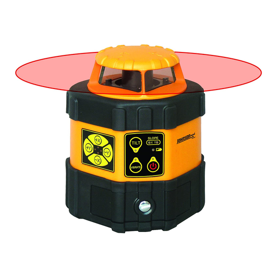
Electronic Self-Leveling Horizontal
Rotary Laser Level
Model No. 40-6537
Instruction Manual
Congratulations on your choice of this Electronic Self-Leveling
Horizontal Rotary Laser Level. We suggest you read this instruction
manual thoroughly before using the instrument. Save this instruction
manual for future use.
This is a Class IIIa laser tool and is manufactured to comply with CFR 21,
parts 1040 .10 and 1040 .11 as well as international safety rule IEC 285.
©2008 Johnson Level & Tool
1
Advertisement
Table of Contents

Subscribe to Our Youtube Channel
Related Manuals for AccuLine 40-6537


Summary of Contents for AccuLine 40-6537
- Page 1 Page 1 ® Electronic Self-Leveling Horizontal Rotary Laser Level Model No. 40-6537 Instruction Manual Congratulations on your choice of this Electronic Self-Leveling Horizontal Rotary Laser Level. We suggest you read this instruction manual thoroughly before using the instrument. Save this instruction manual for future use.
-
Page 2: Table Of Contents
5. Location of Parts/Components 13. Product Registration 6. Operating Instructions 14. Accessories 7. Using the Product 1. Kit Contents Description Model No. 40-6537 Qty. Electronic Self-Leveling Horizontal Rotary Laser Level Ni-MH Rechargeable Battery Pack 6V Battery Adapter Remote Control with 9V Battery Detector with 9V Battery and Quick Clamp 6 “AA”... -
Page 3: Safety Instructions
• Do not attempt to repair or disassemble the laser tool. If unqualified persons attempt to repair this tool, warranty will be void. • Use only original AccuLine Pro ® parts and accessories purchased from your AccuLine Pro ® authorized dealer. Use of non-AccuLine Pro ®... -
Page 4: Location/Content
1467H-English 8/6/08 10:07 AM Page 4 4. Location/Content of Warning Labels LASER RADIATION AVOID DIRECT EYE EXPOSURE. MAXIMUM OUTPUT POWER ≤ 5mW @ 625-645nm CLASS IIIa LASER PRODUCT. THIS PRODUCT COMPLIES WITH THE APPLICABLE REQUIRE- MENTS OF 21 CFR PARTS 1040.10 &... -
Page 5: Location Of Parts/Components
1467H-English 8/6/08 10:07 AM Page 5 5. Location of Part/Components Rotary head Remote control receiver Keypad Laser Output Window Keypad Battery-case locking screw Polarity indication 5/8” - 11 screw thread of battery Battery compartment Adapter plug Charging LED Locking screw Contact Points ©2008 Johnson Level &... -
Page 6: Operating Instructions
1467H-English 8/6/08 10:07 AM Page 6 6. Operating Instructions IMPORTANT: It is the responsibility of the user to verify the calibration of the instrument before each use. Tilt button Slope-direction LED Tilt LED Low battery LED Vibrate-mode LED Power LED Vibrate button Power button Fig. - Page 7 1467H-English 8/6/08 10:07 AM Page 7 Tilt LED: LED light on = Tilt mode on; LED light off = Tilt mode off; Flashing LED light = Tilt in warning mode Beam Shield LED: LED light on = shielding the laser beam in this axis Power on/off: Press button, the lasers power is on, and the power LED...
- Page 8 1467H-English 8/6/08 10:07 AM Page 8 Beam shield mode: Press the Beam Shield button of the axis you wish to shield the beam from. The corresponding LED light will turn on and this direction is shielded. From one to three quadrants can be shielded simultaneously.
- Page 9 1467H-English 8/6/08 10:07 AM Page 9 Press the SLOPE button to enter the SLOPE function. The SLOPE on X-axis is set as the default. SLOPE LED light on in X-axis. Press button to adjust the slope angle on X-axis. Press the SLOPE button again to change the SLOPE to the Y-axis.
-
Page 10: Using The Product
1467H-English 8/6/08 10:07 AM Page 10 7. Using the Product Alkaline Battery Installation Loosen the locking screw, put 6 “AA” alkaline batteries into the battery case according to the polarity indication shown on the battery case. Then put the battery case into the instrument and tighten the locking screw. - Page 11 1467H-English 8/6/08 10:07 AM Page 11 8. Self-Check and Calibration IMPORTANT: It is the responsibility of the user to verify the calibration of the instrument before each use. Accuracy Check 50’ 1. Put the laser on a tripod 50’ away from the wall. Put the laser on the tripod with X+ axis towards wall.
- Page 12 1467H-English 8/6/08 10:07 AM Page 12 Re-calibration Referencing the results of the self-check and using the “h” mark (the mid-point between the highest and the lowest point among A, B, C, D). 1. Enter self-calibration mode a. Power off the instrument and face the X-axis towards the wall. b.
- Page 13 1467H-English 8/6/08 10:07 AM Page 13 axis. The re-calibration LED turns off and the value of the re-calibration will be stored. The laser has now exited re-calibration mode. Note: In order to make the saved calibration effective, you must power off the instrument after calibration, and then power it on again.
-
Page 14: Technical Specifications
1467H-English 8/6/08 10:07 AM Page 14 9. Technical Specifications Laser Wavelength 635nm±10nm Laser Classification Class IIIa ≤5mW Maximum Power Output Accuracy ±1/16"/100 ft. (±1.5mm/30m) Exterior Range Up to 2000 ft. (600m) diameter Remote Range Up to 100 ft. (30m) diameter with remote Auto-Leveling Range ±5°... -
Page 15: Application Demonstrations
1467H-English 8/6/08 10:07 AM Page 15 10. Application Demonstrations Squaring Leveling Grading Set Forms Elevation ©2008 Johnson Level & Tool... -
Page 16: Care And Handling
1467H-English 8/6/08 10:07 AM Page 16 11. Care and Handling This laser unit is a precision tool that must be handled with care. • Avoid exposing unit to shock vibrations and extreme temperatures. • Before moving or transporting the unit, make sure that the unit is •... -
Page 17: Product Warranty
The limited warranty for each product contains various limitations and exclusions. Do not return this product to the store/retailer or place of purchase. Required repair/calibration must be done by an authorized AccuLine ® service center or Johnson Level & Tool's limited warranty, if applicable, will be void and there will be NO WARRANTY. -
Page 18: Product Registration
AccuLine Pro ® accessories are available for purchase through authorized AccuLine Pro dealers. Use of non-AccuLine Pro accessories will void any applicable limited warranty and there will be NO WARRANTY. If you need any assistance in locating any accessories, please contact our Customer Service Department.
Need help?
Do you have a question about the 40-6537 and is the answer not in the manual?
Questions and answers