Table of Contents
Advertisement
Quick Links
Chapter 1. Introduction ...................................................................... 3
1.1
Product Overview ........................................................................ 3
1.2
Specification ................................................................................ 4
1.3
Component Placement ................................................................ 7
1.4
Block Diagram ............................................................................. 8
Chapter 2. Hardware Setup ................................................................ 9
2.1
Jumpers and Connectors Location.............................................. 9
2.2
CPU Setting............................................................................... 12
2.3
CMOS Setting ........................................................................... 12
2.4
Watchdog Timer Setting ............................................................ 13
2.5
Embedded Flash Disk ............................................................... 14
2.6
Power and Fan Connectors....................................................... 15
2.7
Display Interface........................................................................ 16
2.8
Ethernet Interface...................................................................... 17
2.9
Audio Interface .......................................................................... 18
2.10
Serial Port COM2 Mode Configuration ...................................... 19
2.11
Switches and Indicators ............................................................ 20
Chapter 3. BIOS Setup...................................................................... 21
Chapter 4. Driver Installation ........................................................... 23
4.1
Install Board's Software............................................................. 23
4.2
Install Ultra ATA IDE Driver ........................................................ 23
4.3
Install VGA Driver ...................................................................... 23
4.4
Install LAN Driver ...................................................................... 23
4.5
Install Audio Driver .................................................................... 23
4.6
Link to < Website > Homepage ................................................. 23
4.7
Browse this CD.......................................................................... 23
HE-860 User's Manual
Table of Contents
1
Advertisement
Table of Contents

Related Manuals for Commell HE-860


Summary of Contents for Commell HE-860
-
Page 1: Table Of Contents
Install Board’s Software............. 23 Install Ultra ATA IDE Driver ............23 Install VGA Driver ..............23 Install LAN Driver ..............23 Install Audio Driver ..............23 Link to < Website > Homepage ..........23 Browse this CD................23 HE-860 User’s Manual... - Page 2 Floppy Port................32 Parallel Port ................33 RS-232 Serial Port ..............34 USB Port ................... 35 IrDA Port ................... 35 VGA Port ................... 36 LAN Port ................... 36 AT Keyboard Port..............37 C.10 PS/2 Keyboard and Mouse Port..........37 HE-860 User’s Manual...
-
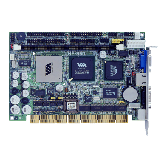
Page 3: Chapter 1. Introduction
533 MHz of speed at 133 MHz of FSB, provides 1 GBytes/sec of data transfer rate. Based on x86 architecture and VIA's latest technology, HE-860 supports most of the x86-based OS and AP. That is, with HE-860, the embedded systems can be integrated and upgraded easily with the existent and popular x86-based software. -
Page 4: Specification
Specification General Specification Form Factor HE-860 : PISA 1.7 compliant, with 4 bus master PCI HE-860S : ISA bus interface only Onboard VIA Eden 533 MHz CPU at 133 MHz FSB Optional Compatible CPU Configuration for OEM VIA Eden 400, 667 MHz CPU (fan free operating) -
Page 5: Solid State Disk Interface
External RJ45 with LED on bracket Audio Interface Chipset VIA 686B built-in AC97 3D audio controller with onboard ALC201A codec Interface Line-in, line-out, Mic-in and CD-in interface Connector Internal 10-pin header for line-in, line-out and mic-in Internal 4-pin wafer for CD-in HE-860 User’s Manual... - Page 6 HE-860SVXL Same as HE-860SVL but with onboard TMDS Panel Link Interface OEM Version Other Configuration Based on HE-860 with Compatible Eden/C3 CPU, Optional Onboard Functions and Others for OEM Projects Online product information detail and updates are available on http://www.commell.com.tw...
-
Page 7: Component Placement
Dual UltraATA/100 IDE Embedded VIA Eden / C3 CPU VIA Eden Ultra Low Voltage CPU for Fan Free Operation VIA EBGA C3 CPU with Onboard CPU Cooling Fan Same Location on HE-860S (Half-size ISA Bus CPU Card) HE-860 User’s Manual... -
Page 8: Block Diagram
10/100 Mbps 8100B HE-860VL HE-860VXL ATA100 IDE ATAPI Device PISA Backplane 686B Codec Audio Devices USB Devices 64mA ISA PS/2 Keyboard PS/2 Mouse ISA Bus Interface HE-860SVL Floppy 64mA ISA HE-860SVXL Serial Device ISA Backplane DiskOnChip Parallel Device HE-860 User’s Manual... -
Page 9: Chapter 2. Hardware Setup
PWRCON1 ATXCON JAT_KB CDIN JLAN JCSEL2 (J2) JRTC JCSEL1 (JCSEL) JAUDIO JCOM2 JPVOD1 (VXL Only) PRINTER JTMDS SWDT JDOC IDE2 JWDT IDE1 DOC (U5) DIMM1 CPUFAN JDOM JFRNT Same Location on HE-860S (Half-size ISA Bus CPU Card) HE-860 User’s Manual... - Page 10 Watchdog Timer Timeout Value Setting JDOC DiskOnChip Address Setting 2.5.1 JDOM DiskOnModule Power Setting 2.5.2 JPVOD1 TMDS Voltage Setting JLAN LAN Enable / Disable Setting JCSEL1 (JCSEL) COM2 RS232/422/485 Mode Setting 2.10 JCSEL2 (J2) COM2 RS232/422/485 Mode Setting 2.10 HE-860 User’s Manual...
- Page 11 VXL only DB15 Female VGA Port on Bracket Standard 6-pin MiniDIN PS/2 Keyboard and Mouse Standard Connector on Bracket LAN_CON RJ45 Primary LAN Port on Bracket VL, VXL only COM1 DB9 Male COM1 Port on Bracket Standard HE-860 User’s Manual...
-
Page 12: Cpu Setting
The board’s data of CMOS can be setting in BIOS. If the board refuses to boot due to inappropriate CMOS settings, here is how to proceed to clear (reset) the CMOS to its default values. Jumper: JRTC Type: onboard 3-pin header JRTC Mode Clear CMOS Normal Operation Default setting JRTC HE-860 User’s Manual... -
Page 13: Watchdog Timer Setting
Active NMI Reset Default setting SWDT JWDT 2.4.2 Watchdog Timer Time-out Value Setting Jumper: SWDT Type: onboard 4-way DIP Switch Time-out Value SWDT 1 Sec. 2 Sec. 10 Sec. 20 Sec. 110 Sec. 220 Sec. Default setting HE-860 User’s Manual... -
Page 14: Embedded Flash Disk
Jumper: JDOC Type: onboard 4-pin header JDOC DiskOnChip Address D000h D800h Default setting JDOM JDOC 2.5.2 DiskOnModule or DiskOnChip 2000 IDE Pro Jumper: JDOM Type: onboard 2-pin header JDOM +5V on Pin-20 of IDE2 Disable Enable Default setting HE-860 User’s Manual... -
Page 15: Power And Fan Connectors
+12V -12V Ground Ground Connector: ATXCON Type: 3-pin Header for ATX Function Description Description Description 5V Standby Ground Power On Connector: CPUFAN Type: 3-pin Header for CPU or System Fan Description Description Description Fan Ctrl +12V Ground HE-860 User’s Manual... -
Page 16: Display Interface
JTMDS Jumper: JPVOD1 Type: onboard 3-pin header JPVOD1 TMDS Panel Voltage Setting +3.3V Default setting Connector: JTMDS Type: 20-pin header Description Description TX1+ TX1- SHLD1 SHLDC TXC+ TXC- Ground TX2+ TX1+ SHLD2 SHLD0 TX0+ TX0- DDC_Data DDC_Clock HE-860 User’s Manual... -
Page 17: Ethernet Interface
IEEE 802.3U compliant, connects with RJ45 connector on bracket. The LAN function can enable or disable by jumper JLAN. Jumper: JLAN Type: onboard 3-pin header JLAN LAN Enable / Disable Setting Enable Disable Default setting JLAN HE-860 User’s Manual... -
Page 18: Audio Interface
Connector: JAUDIO Type: 10-pin header Description Description Line – Right Ground Line – Left Ground Line Out – Left Line Out – Right Ground Connector: CDIN Type: 4-pin header Description CD – Left Ground Ground CD – Right HE-860 User’s Manual... -
Page 19: Serial Port Com2 Mode Configuration
Jumper: JCSEL1 (JCSEL), JCSEL2 (J2) Type: onboard 6-, 12-pin header COM2 Mode JCSEL2 (J2) JCSEL1 (JCSEL) RS-232 1-2/4-5/7-8/10-11 RS-422 2-3/5-6/8-9/11-12 RS-485 2-3/5-6/8-9/11-12 Default setting Connector: JCOM2 Type: 10-pin header Pin RS232 RS422 RS485 Pin RS232 RS422 RS485 485- 485+ Ground HE-860 User’s Manual... -
Page 20: Switches And Indicators
10-pin JFRNT includes additional speaker and power LED cables in the packing list. Connector: JFRNT (Type-II) Type: onboard 14-pin header Function Signal Signal Function Vcc (+) (+) Vcc IDE LED Power Active Reset Reset Speaker Power PWRBT Button SPKIN HE-860 User’s Manual... -
Page 21: Chapter 3. Bios Setup
Set Supervisor Password >Power Management Setup Set User Password >PnP / PCI Configurations Save & Exit Setup >PC Health Status Exit Without Saving ↑ ↓ → ← : Select Item Esc : Quit F10 : Save & Exit Setup HE-860 User’s Manual... - Page 22 Notes (This page left blank intentionally) HE-860 User’s Manual...
-
Page 23: Chapter 4. Driver Installation
Link to < Website > Homepage The selection help you to link to the website to find the updated technical documents and download directly. Browse this CD The selection helps you to find the drivers in this CD directly. HE-860 User’s Manual... - Page 24 Notes (This page left blank intentionally) HE-860 User’s Manual...
-
Page 25: Appendix A. System Resources
Realtek RTL8139(A) PCI Fast Ethernet Adapter 0x0020-0x0021 Programmable interrupt controller 0x00A0-0x00A1 Programmable interrupt controller 0x0040-0x0043 System timer 0x0000-0x000F Direct memory access controller 0x0081-0x0083 Direct memory access controller 0x0087-0x0087 Direct memory access controller 0x0089-0x008B Direct memory access controller HE-860 User’s Manual... - Page 26 PC/AT Enhanced PS/2 Keyboard (101/102-Key) 0x0378-0x037F Printer Port (LPT1) 0x03F8-0x03FF Communications Port (COM1) 0x02F8-0x02FF Communications Port (COM2) 0x03F0-0x03F5 Standard floppy disk controller 0x03F7-0x03F7 Standard floppy disk controller 0x0061-0x0061 System speaker 0x0070-0x0071 System CMOS/real time clock 0x00F0-0x00FF Numeric data processor HE-860 User’s Manual...
-
Page 27: Memory Address Map
VIA Tech VT8361/VT8601 Graphics Controller 5.12.01.3105 0xE7000000-0xE70000FF Realtek RTL8139(A) PCI Fast Ethernet Adapter 0x0000-0x9FFFF System board 0xFFFE0000-0xFFFFFFFF System board 0xFEE00000-0xFEE0FFFF System board 0x100000-0xFFFFFF System board 0xF0000-0xF3FFF Motherboard resources 0xF4000-0xF7FFF Motherboard resources 0xF8000-0xFBFFF Motherboard resources 0xFC000-0xFFFFF Motherboard resources HE-860 User’s Manual... -
Page 28: System Irq And Dma Resource
Primary IDE controller (dual fifo) VIA Bus Master PCI IDE Controller Secondary IDE controller (dual fifo) VIA Bus Master PCI IDE Controller A.3.2 Range Device (free) (free) Standard Floppy Disk Controller (free) Direct memory access controller (free) (free) (free) HE-860 User’s Manual... -
Page 29: Appendix B. Flash The Bios
Get the “.bin” file including the image of new BIOS you want to update. Power on the system and flash the BIOS. Re-star the system. Any question about the BIOS re-flash please contact your distributors or visit the web-site at below: http://www.commell.com.tw/Support/Support.htm HE-860 User’s Manual... - Page 30 Notes (This page left blank intentionally) HE-860 User’s Manual...
-
Page 31: Appendix C. I/O Port Pin Assignment
Ground CBLID CS0 (MASTER CS) CS1 (SLAVE CS) LED ACT- Ground Note: The pin-20 of IDE1 is jumper selectable as +5V Vcc for the DOM (DiskOnModule) or DiskOnChip IDE Pro flash disk without the additional power cable. HE-860 User’s Manual... -
Page 32: Floppy Port
Ground DRIVER SELECT B- Ground DRIVER SELECT A- Ground MOTOR ENABLE B- Ground DIRECTION- Ground STEP- Ground WRITE DATA- Ground WRITE GATE- Ground TRACK 0- Ground WRITE PROTECT- Ground READ DATA- Ground HEAD SELECT- Ground DISK CHANGE- HE-860 User’s Manual... -
Page 33: Parallel Port
Parallel Port Connector: PRINTER Type: 26-pin header Description Description STROBE- AUTO FEED- ERROR- INITIALIZE- SELECT INPUT- Ground Ground Ground Ground Ground ACKNOWLEDGE- Ground BUSY Ground PAPER EMPTY Ground SELECT+ HE-860 User’s Manual... -
Page 34: Rs-232 Serial Port
RS-232 Serial Port C.4.1 Onboard RS-232 Serial Port Connector: JCOM2 Type: 10-pin header Description Description Ground C.4.2 On Bracket RS-232 Serial Port Connector: COM1 Type: 9-pin D-sub male connector on bracket Description Description Ground HE-860 User’s Manual... -
Page 35: Usb Port
USB Port Connector: USB Type: 10-pin header for dual USB Ports Description Description Data0- Data1- Data0+ Data2+ Ground Ground Ground Ground IrDA Port Connector: SIR Type: 5-pin header for SIR Ports Description IRRX Ground IRTX HE-860 User’s Manual... -
Page 36: Vga Port
VGA Port Connector: VGA Type: 15-pin D-sub female connector on bracket Description Description Description Ground GREEN Ground VDDAT BLUE Ground HSYNC VSYNC Ground Ground VDCLK LAN Port Connector: LAN_CON1 Type: RJ45 connector on bracket Description HE-860 User’s Manual... -
Page 37: At Keyboard Port
Type: 6-pin MiniDIN connector on bracket Description Ground Note: The PS/2 connector supports standard PS/2 keyboard directly or both PS/2 keyboard and mouse through the PS/2 Y-type cable. The cable is the standard one in the packing list HE-860 User’s Manual...
Need help?
Do you have a question about the HE-860 and is the answer not in the manual?
Questions and answers