Advertisement
Quick Links
Advertisement

Related Manuals for Commell HS-873P


Summary of Contents for Commell HS-873P
- Page 1 HS-873P Half-size Single Board Computer User’s Manual Edition: 1.2 2011/09/13...
- Page 2 HS-873P User’s Manual Copyright Copyright 2009. All rights reserved. This document is copyrighted and all rights are reserved. The information in this document is subject to change without prior notice to make improvements to the products. This document contains proprietary information and protected by copyright. No part of this document may be reproduced, copied, or translated in any form or any means without prior written permission of the manufacturer.
-
Page 3: Packing List
HS-873P User’s Manual Packing List: Please check the package material before you install the system. Hardware: HS-873P Single Board Computer x 1 Cable Kit: 4-pin to 3-pin ATX cable x 1 (OAL-ATX-C) Floppy flat cable x 1 (OALFD) CPU Cooler x 1 SATA Cable x 2 PS/2 Keyboard &... - Page 4 HS-873P User’s Manual Index Chapter 1 <Introduction> ..................6 1.1 <Product Overview> ................6 1.2 <Product Specification> ................ 7 1.3 < Mechanical Drawing > ................ 9 1.4 <Block Diagram> .................. 10 Chapter 2 <Hardware Setup> ................11 2.1 <Connector Location> ................. 11 2.2.1 <Internal Connector>...
- Page 5 HS-873P User’s Manual Chapter 3 <System Configuration> ..............34 3.1 <Audio Setting> ..................34 Chapter 4 <BIOS Setup> ..................35 Appendix A <I/O Port Pin Assignment> ............36 A.1 <Parallel Port>..................36 A.2 <Serial ATA Port> ................. 36 A.3 <Floppy Port> ..................37 A.4 <IrDA Port>...
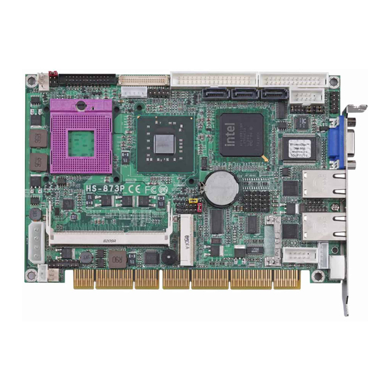
- Page 6 Chapter 1 <Introduction> 1.1 <Product Overview> The HS-873P is an all-in-one single board computer with PISA bus with supporting Intel Penryn processor for 667/800/1066 MHz front side bus, Intel GM45 and ICH9-M chipset, integrated GMA4500MHD graphics, DDR3 SDRAM memory, Realtek HD Audio, Serial ATA and two Intel 82574L Gigabit LAN.
- Page 7 HS-873P User’s Manual Introduction 1.2 <Product Specification> General Specification Form Factor Half-size PISA CPU card Intel® Penryn processor Package type: Micro- FCPGA478 (Socket-P) Front side bus: 667/800/1066 MHz Memory 2 x 204-pin DDR3 800/1066 MHz SDRAM up to 8GB Unbuffered, none-ECC memory supported only Chipset Intel®...
- Page 8 HS-873P User’s Manual Introduction ISA Interface ISA Bridge Winbond W83628AG & W83629AG Function I/O & IRQ supported only, no support DMA & bus mastering Audio Interface Chipset Intel® ICH9M with Realtek ALC888 HD Audio Intel High Definition Audio compliance Interface...
- Page 9 HS-873P User’s Manual Introduction 1.3 < Mechanical Drawing > Mechanical Drawing...
- Page 10 HS-873P User’s Manual Introduction 1.4 <Block Diagram> Intel Penryn Processor 2 x 204-pin DDR3 800/1066 MHz up Intel GMA 4500MHD Graphics to 8 HDTV&LVDS&DVI GM45 PCI Express mini card 3 x SATAII HD Audio 6 x USB2.0 ports ICH9-M Intel 82574L...
- Page 11 HS-873P User’s Manual Introduction Chapter 2 <Hardware Setup> 2.1 <Connector Location> CN_COM2 SATA1/2/3 CN_LVDS CN_DVI CN_LPT CPUFAN CN_INV CN_HDTV CN_AUDIO CN_USB1/2/3 CN_IR CD_IN CN_DIO CN_SMBUS CN_BPWR CN_ATKB JFRNT CN_PS SO-DIMM1 SYSFAN CN_COM1 Connector Location...
- Page 12 HS-873P User’s Manual Hardware Setup SO-DIMM2 HS-873PXG2 & HS-873PXDG2 RJ45_1 RJ45_2 HS-873PXG & HS-873PXDG Connector Reference...
- Page 13 HS-873P User’s Manual Introduction 2.2 <Connector Reference> 2.2.1 <Internal Connector> Connector Function Remark DDRIII 1/2 204–pin DDR3 SDRAM DIMM socket Standard 26-pin floppy connector Standard SATA1/2/3 7-pin Serial ATA connector Standard CN_BPWR 4-pin AT power supply connector Standard CN_PS 3-pin ATX function connector...
- Page 14 HS-873P User’s Manual Hardware Setup 2.3 <Jumper Reference> Jumper Function JRTC CMOS Operating/Clear Setting JVLCD LCD Panel Voltage Setting JCSEL1/2 COM2 RS232/422/485 mode setting Power mode select JCSEL2 JCSEL1 JVLCD JRTC Jumper Reference...
- Page 15 HS-873P User’s Manual 2.4 <CPU and Memory Setup> 2.4.1 <CPU Setup> Socket-P The board comes with the socket 478 for Intel Penryn processor only it supports new generation with 667/800/1066 MHz of front side bus. Please follow the instruction to install the CPU properly.
- Page 16 Hardware Setup 2.4.2 <Memory Setup> HS-873P has two 204-pin DDR3 DIMM support up to 8GB of memory capacity. The memory frequency supports 800/1066 MHz. Only Non-ECC memory is supported. Dual-Channel technology is supported while applying two same modules on one of each group.
- Page 17 HS-873P User’s Manual 2.5 <CMOS Setup> The board’s data of CMOS can be setting in BIOS. If the board refuses to boot due to inappropriate CMOS settings, here is how to proceed to clear (reset) the CMOS to its default values.
- Page 18 HS-873P User’s Manual Hardware Setup 2.6 <Serial ATA interface> Based on Intel ICH9-M, the board provides two Serial ATAII interfaces with up to 300MB/s of transfer rate SATA1/2/3 2.7 <LAN Interface> The Intel 82574L supports triple speed of 10/100/1000Base-T, with IEEE802.3 compliance and Wake-On-LAN supported.
- Page 19 HS-873P User’s Manual 2.8 <Onboard Display Interface> Based on Intel GM45 chipset with built-in GMA (Graphic Media Accelerator) 4500MHD graphics, the board provides one DB15 connector on real external I/O port, and one 40-pin LVDS interface with 5-pin LCD backlight inverter connector. The board provides dual display function with clone mode and extended desktop mode for CRT and LCD and TV-out and DVI (HS-873PXDG/G2).
- Page 20 HS-873P User’s Manual Hardware Setup 2.8.2 <Digital Display> The board provides one 40-pin LVDS connector for 18/24-bit dual channel panels, supports up to 1600 x 1200 (UXGA) of resolution, with one LCD backlight inverter connector and one jumper for panel voltage setting.
- Page 21 HS-873P User’s Manual Connector: CN_INV Connector: JVLCD Type: 5-pin LVDS Power Header Type: 6-pin Power select Header Description Description +12V LCDVCC (3.3V) Reserved (Note) LCDVCC (5V) LCDVCC (12V) Default: 1-2 ENABKL Note: Reserved for MB internal test Please treat it as NC.
- Page 22 LCD Installation Guide: Preparing the HS-873P, LCD panel and the backlight inverter. Please check the datasheet of the panel to see the voltage of the panel, and set the jumper JVLCD to +12V or +5V or +3.3V.
- Page 23 HS-873P User’s Manual The board also comes with a DVI interface with Chrontel CH7307C for digital video interface. After setup the devices well, you need to select the LCD panel type in the BIOS. The panel type mapping is list below: BIOS panel type selection form (BIOS Version:1.0)
- Page 24 HS-873P User’s Manual Hardware Setup 2.8.3 <DVI Interface > Connector: CN_DVI Connector type: 26-pin header connector (pitch = 2.00mm) Pin Number Assignment Pin Number Assignment TX1+ TX1- Ground Ground TXC+ TXC- Ground PVDD TX2+ TX2- Ground Ground TX0+ TX0- HPDET...
- Page 25 HS-873P User’s Manual 2.8.4 <TV-Out Interface> The board provides an HDTV interface with Intel GM45, supports PAL and NTSC of TV system, and display (clone or extended desktop) function with CRT, LVDS, DVI. Connector: CN_HDTV Connector type: 10-pin header HDTV connector (pitch = 2.54mm)
- Page 26 HS-873P User’s Manual Hardware Setup To connect the TV set, please follow the diagram below to setup your system: YPrPb Component Cable (For HDTV) TV-Out Interface...
- Page 27 HS-873P User’s Manual 2.9 <Onboard Audio Interface> The board provides the onboard HD audio interface with Realtek ALC888 Connector: CN_AUDIO Type: 10-pin (2 x 5) 1.27mm x 2.54mm-pitch header Description Description MIC2_L Ground MIC2_R FP_OUT_R MIC2_JD SENSE_B FP_OUT_L LINE2_JD Connector: CDIN Type: 4-pin header (pitch = 2.54mm)
- Page 28 HS-873P User’s Manual Hardware Setup 2.10 <USB2.0 Interface> Based on Intel ICH9-M, the board provides 6 USB2.0 ports. The USB2.0 interface provides up to 480Mbps of transferring rate. Interface USB2.0 Controller ICH9-M Transfer Rate Up to 480Mb/s Output Voltage 500mA...
- Page 29 HS-873P User’s Manual 2.11 <Serial Port Jumper Setting > The board supports one RS232 serial port and one jumper selectable RS232/422/485 serial ports. The jumper JCSEL1 & JCSEL2 can let you configure the communicating modes for COM2. Connector: CN_COM1 Type: 10-pin (5 x 2) 2.54mm x 2.54mm-pitch header for COM1...
- Page 30 HS-873P User’s Manual Hardware Setup CN_COM2 CN_COM1 2.12 <Power and Fan Installation> The board comes with a 4-pin AT power connector for powering the board, three fan connectors for Northbridge, CPU and system. The board also provides a 3-pin ATX function connector.
- Page 31 HS-873P User’s Manual 2.12.2 <Fan Connectors> Connector: CPUFAN Type: 4-pin fan wafer connector Description Description Ground +12V Fan Speed Detection Fan Control Connector: SYSFAN Type: 3-pin fan wafer connector Pin Description Description Pin Description Ground +12V Fan Speed Detection CPUFAN...
- Page 32 HS-873P User’s Manual Hardware Setup 2.13 <GPIO Interface> The board provides a 12-pin General Purpose I/O interface, with programmable 8-bit I/O (4-bit input & 4-bit output). Connector: CN_DIO Type: onboard 2 x 6-pin header, pitch=2.0mm Description Description Ground Ground GP10...
- Page 33 HS-873P User’s Manual 2.13 <Switch and Indicator> The JFRNT provides front control panel of the board, such as power button, reset and beeper, etc. Please check well before you connecting the cables on the chassis. Connector: JFRNT Type: onboard 14-pin (2 x 7) 2.54-pitch header...
- Page 34 HS-873P User’s Manual System Configuration Chapter 3 <System Configuration> 3.1 <Audio Setting> The board integrates Intel® ICH9M with REALTEK® ALC888 codec. It can support 2 channels sound under system configuration. Please follow the steps below to setup your sound system.
- Page 35 HS-873P User’s Manual BIOS Setup Chapter 4 <BIOS Setup> The motherboard uses the Award BIOS for the system configuration. The Award BIOS in the single board computer is a customized version of the industrial standard BIOS for IBM PC AT-compatible computers. It supports Intel x86 and compatible CPU architecture based processors and computers.
- Page 36 HS-873P User’s Manual I/O Port Pin Assignment Appendix A <I/O Port Pin Assignment> A.1 <Parallel Port> Connector: LPT Type: 26-pin (13 x 2) box header Description Description -PSTB AFD- PRO0 ERR- PRO1 INT- PRO2 SLIN- PRO3 Ground PRO4 Ground PRO5...
- Page 37 HS-872P User’s Manual A.3 <Floppy Port> Connector: FDD Type: 34-pin connector Description Description INDEX DSKCHG MTR0 DRVDE0 STEP Ground WRITE DATA Ground WRITE GATE Ground TRAK 0 WRPTO Ground RDATA- Ground HDSEL A.4 <IrDA Port> Connector: CN_IR Type: 5-pin header for SIR Ports Description IRRX Ground...
- Page 38 HS-873P User’s Manual I/O Port Pin Assignment A.5 <VGA Port> Connector: CRT Type: 15-pin D-sub female connector on bracket Description Description Description Ground GREEN Ground 5VCDA BLUE Ground HSYNC LVGA5V VSYNC Ground Ground 5VCLK A.6 <LAN Port> Connector: RJ45_1/2 Type: RJ45 connector with LED on rear panel...
- Page 39 HS-872P User’s Manual A.8 <AT Keyboard Port> Connector: CN_ATKB Type: 5-pin box header Description Ground DATA A.9 <PS/2 Keyboard & Mouse Port> Connector: PS2 Type: 6-pin Mini-DIN connector on bracket Description Ground Note: The PS/2 connector supports standard PS/2 keyboard directly or both PS/2 keyboard and mouse through the PS/2 Y-type cable.
- Page 40 HS-873P User’s Manual Flash BIOS Appendix B <Flash BIOS> B.1 BIOS Auto Flash Tool The board is based on Award BIOS and can be updated easily by the BIOS auto flash tool. You can download the tool online at the address below: h ttp://www.award.com...
- Page 41 HS-873P User’s Manual Appendix C <System Resources> C.1 <I/O Port Address Map>...
- Page 42 HS-873P User’s Manual...
- Page 43 HS-873P User’s Manual C.2 <Memory Address Map>...
- Page 44 HS-873P User’s Manual System Resources C.3 <System IRQ Resources> System IRQ Resources...
- Page 45 HS-873P User’s Manual Programming GPIO’s Appendix D <Programming GPIO’s> The GPIO can be programmed with the MSDOS debug program using simple IN/OUT commands. The following lines show an example how to do this. GPIO0...GPIO7 bit0……bit7 -o 2E 87 ;enter configuration...
- Page 46 HS-873P User’s Manual Watch Dog timer Setting Appendix E <Watch Dog timer Setting > The watchdog timer makes the system auto-reset while it stops to work for a period. The integrated watchdog timer can be setup as system reset mode by program.
-
Page 47: Contact Information
Taiwan Commate Computer Inc. 19F., No.94, Sec. 1, Xintai 5th Rd., Xizhi Dist., Address New Taipei City 22102, Taiwan +886-2-26963909 Website http://www.commell.com.tw E-Mail info@commell.com.tw (General Information) tech@commell.com.tw (Technical Support) Commell is our trademark of industrial PC division Contact Information...
Need help?
Do you have a question about the HS-873P and is the answer not in the manual?
Questions and answers