Table of Contents
Advertisement
Quick Links
Advertisement
Table of Contents

Related Manuals for Commell LE-37D


Summary of Contents for Commell LE-37D
- Page 1 LE-37D 3.5 inch Motherboard User’s Manual Edition 1.6 2015/04/02...
-
Page 2: Packing List
Any questions please visit our website at h ttp://www.commell.com.tw Packing List: Please check the package content before you starting using the board. Hardware: LE-37D 3.5 inch Miniboard x 1 (include Cooler Fan) Cable Kit: SATA Cable x 1 COM Port Cable x 1... - Page 3 1 to 3 power output cable x 1 SATA Power Cable x 1 (OAL4P-2)/ (1040051) (OAL4P-S2)/ (1040054) DC Power Cable x 1 (OALDC-A)/ (1040433) Audio Cable x 1 (OALPJ-HDUNB)/ (1040123) PS/2 Keyboard & Mouse Cable x 1 (OALPS2/KM)/ (1040131) USB2.0 Cable x 1 (OALUSBA-3)/ (1040173) Printed Matters: CRT cable without bracket x 1...
- Page 4 Index Chapter 1 <Introduction> ................5 1.1 <Product Overview> ..................5 1.2 <Product Specification>................6 1.3 <Mechanical Drawing> ................. 8 1.4 <Block Diagram>..................9 Chapter 2 <Hardware Setup>..............10 2.1 <Connector Location> ................10 2.2 <Jumper Location & Reference>..............10 2.3 <Connector Reference> ................11 2.3.1 <Internal Connectors>...
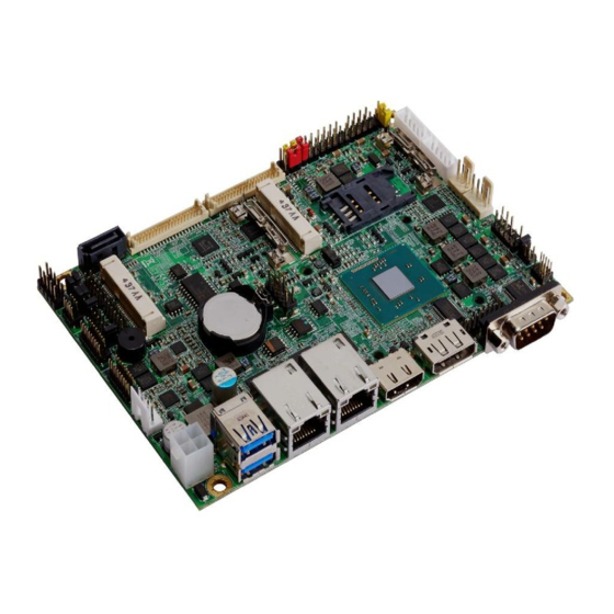
- Page 5 Chapter 1 <Introduction> 1.1 <Product Overview> The LE-37D motherboard is design based on Intel® Celeron® Processor J1900 / N2930 and Intel® Atom Processor E3845, delivering outstanding compute, graphical, and media performance while operating in an extended range of thermal conditions. The SoC bases on the Silvermont microarchitecture, utilizing Intel’s industry-leading 22nm...
-
Page 6: Product Specification
supports graphics, media performance, flexibility and more enhanced security that is suitable for a variety of intelligent systems the ideal choice. Outstanding integration of I/O interfaces Supports display interfaces with graphics processing, camera interfaces with image processing, audio with digital signal processing, multiple storage types, and legacy embedded I/O. - Page 7 Intel Atom Processor E3845 (2M Cache, 1.91GHz), 2 x LVDS, CRT, Gigabit LAN, USB3.0 & 2.0, Serial Port, SATAII, Audio, PCIE Mini card, SMBUS, GPIO, SIM, LPC, mSATA, CFast The specifications may be different as the actual production. For further product information please visit the website at http://www.commell.com.tw...
-
Page 8: Mechanical Drawing
1.3 <Mechanical Drawing>... -
Page 9: Block Diagram
1.4 <Block Diagram>... -
Page 10: Chapter 2
Chapter 2 <Hardware Setup> 2.1 <Connector Location> 2.2 <Jumper Location & Reference> Jumper Function JRTC CMOS Operating/Clear Setting JVLCD Panel Voltage Setting Power mode select Com1 Voltage Setting (For Pin 9) Com2 Voltage Setting (For Pin 9) JCSEL1 CN_COM2 RS-232 RS422 RS485 Setting JCSEL2 CN_IR Setting JVUSB1... -
Page 11: Connector Reference
2.3 <Connector Reference> 2.3.1 <Internal Connectors> Connector Function Remark FCBGA 1170 CPU SO-DIMM 204 -pin DDR3L SO-DIMM slot SATA 7-pin Serial ATA2 connector DC_IN DC 6~27V input connector DC_OUT 4-pin DC output connector CN_AUDIO 5 x 2-pin audio connector CN_DIO 6 x 2-pin digital I/O connector CN_USB 2/3 5 x 2-pin USB2.0 connector... -
Page 12: Cfast Setup
Support Non-ECC, unbuffered memory only SO-DIMM 2.4.2 < CFAST Setup > The board provide one CFAST slot which supports SATA2 interface. The CFAST has the same size with CF card, but it shows higher efficiency and stability to transmit SATA signal. CFAST plug closeup Installing the CFAST in the back of the board. -
Page 13: Cmos & Atx Setup
2.5 <CMOS & ATX Setup> The board’s data of CMOS can be setting in BIOS. If the board refuses to boot due to inappropriate CMOS settings, here is how to proceed to clear (reset) the CMOS to its default values. Jumper: JRTC Type: Onboard 3-pin jumper JRTC... -
Page 14: Serial Ata Interface
2.6 <Serial ATA Interface> LE-37D has one SATAII interface, the transfer rate of the SATAII can be up to 300MB/s. 2.7 <Ethernet Interface> The board integrates with two Intel® I210-AT controllers, The Intel Gigabit Ethernet supports triple speed of 10/100/1000Base-T, with IEEE802.3 compliance. - Page 15 Effective patterns of connection: 1-2 / 3-4 / 5-6 Warning: others cause damages Connector: JVLCD (LVDS1 voltage and LVDS2 voltage must be the same) Type: 6-pin Power select Header Description (3.3V) LCDVCC (5V) LCDVCC (12V) LCDVCC Default: 1-2...
- Page 16 Connector: CN_INV Type: 5-pin LVDS Power Header Description +12V ENABKL Connector: CN_LVDS Type: onboard 40-pin connector for LVDS connector Connector model: HIROSE DF13-40DP-1.25V or compatible Signal Signal LCDVCC LCDVCC LVDS Detect (Note) ATX0- BTX0- ATX0+ BTX0+ ATX1- BTX1- ATX1+ BTX1+ ATX2- BTX2- ATX2+...
- Page 17 LCD Installation Guide: Preparing the LE-37D, LCD panel and the backlight inverter. Please check the datasheet of the panel to see the voltage of the panel, and set the jumper JVLCD to +12V or +5V or +3.3V.
- Page 18 BIOS panel type selection form (BIOS Version:1.0) Single / Dual channel Single / Dual channel Output format Output format 640 x 480 1680 x 1050 800 x 600 1920 x 1200 1024 x 768 1440 x 900 1280 x 1024 1600 x 900 1400 x 1050 1024 x 768...
-
Page 19: Integrated Audio Interface
MIC_R Speaker_R MIC Detect SENSE Speaker_L Speaker Detect 2.10 <USB Interface> LE-37D integrates 5 x USB2.0 and 1 x USB3.0. The specifications of USB3.0 are listed below: Interface USB3.0 Controller J1900 / N2930 / E3845 Transfer Rate Up to 5Gb/s Voltage The USB3.0 port need to Install USB 3.0 eXtensible Host Controller Driver and... - Page 20 Step2. Configure default BIOS, click Advanced > South Cluster Configuration > USB Configuration, disable “EHCI Mode”. Step3. enable “xHCI Mode” and push “F10” to save configuration. Restart your computer. Step4. If you enable xHCI Mode , USB 2.0 and USB 3.0 ports can’t use without drive.
- Page 21 Step6. Lastly, the “Setup Complete” screen appears so click “Finish” to restart your computer. The specifications of USB2.0 are list Interface USB2.0 Controller J1900 / N2930 / E3845 Transfer Rate Up to 480Mb/s Voltage...
-
Page 22: Serial Port
Connector: CN_USB 2/3 Type: 10-pin (2 x 5) header (pitch = 2.54mm) Description Description Data0- Data1- Data0+ Data1+ Ground Ground Ground CN_USB2 need to enable xHCI Mode 2.11 <Serial Port> The board supports one RS232 serial port and one jumper selectable RS232/422/485 serial ports. - Page 23 Connector: COM2 Type: 10-pin (5 x 2) 1.27mm x 2.54mm-pitch header for COM2 Function JCSEL2 JCSEL1 RS-422 RS-485 RS-232 (Default) Setting RS-232 & RS-422 & RS-485 for COM2 Connector: COM3/4 COM5/6 Type: 19-pin (2 x 10) header pitch = 2.54x1.27mm Description Description DCD1...
-
Page 24: Pcie Mini Card And Sim Interface
Jumper: JCSEL1,JCSEL2 Type: 12-pin (6 x 2) & 8-pin (4 x 2) for set COM2 mode jumper Power Mode JP1/2 Pin 9 with 5V Power Pin 9 with 12V Power Standard COM port Default setting (5-6) 2.12 <PCIe Mini Card and SIM Interface> The board provides two PCIe mini card slot and a SIM slot. -
Page 25: Sim Setup
Connector: SIMM (3G MiniPcie Mode) Type: 6-pin SIM slot Description Description SIMVCC SIMRST SIMCLK SIMVPP SIMDATA Connector: JMSATA Type: onboard 3-pin header JMSATA Mode Support mSATA for MINI_CARD1 Support PCIe and USB Default setting: 2-3 2.12.1 <SIM Setup> Step1. SIM card holder is marked by circle. Slide the cap toward OPEN direction. - Page 26 Step 2. Make sure that the cap is now at the OPEN position. Step 3. Flip the cap up for inserting a SIM card into. Step 4. Insert a SIM card as shown in the photo. Be sure that the corner cut is on top and the golden pads are up. Step 5.
-
Page 27: Gpio And Smbus Interface
Step 6. Press down and slide the cap to the CLOSE position. Be sure that the cap is tightly held with the slot. 2.13 <GPIO and SMBUS Interface> The board provides a programmable 8-bit digital I/O interface; you can use this general purpose I/O port for system control like POS or KIOSK. -
Page 28: Power Supply And Fan Interface
Connector: CN_SMBUS Type: 5-pin header for SMBUS Ports Description SMBDATA SMBCLK Ground 2.14 <Power Supply and Fan Interface > 2.14.1 <Power Input> The board requires DC input with 4-pin header, the input voltage range is from 6V to 27V. Connector: DC_IN Type: 4-pin DC power connector Description Description... -
Page 29: Fan Connector
2.14.3 <Fan connector> The board provides one 4-pin fan connectors supporting smart fan for CPU cooler and system cooler. Connector: CPUFAN Type: 4-pin fan wafer connector Description Description Ground +12V Fan Speed Detection Fan Control Connector: SYSFAN Type: 4-pin fan wafer connector Description Description Ground... -
Page 30: Switch And Indicator
2.15 <Switch and Indicator> The JFRNT provides front control panel of the board, such as power button, reset and beeper, etc. Please check well before you connecting the cables on the chassis. Connector: JFRNT Type: onboard 10-pin (2 x 5) 2.54-pitch header Function Signal Signal... -
Page 31: Display Properties Setting
Select Speaker Configuration 3.2 <Display Properties Setting> Based on Intel J1900/N2930/E3845 with HD Graphic, the board supports two DACs for display device as different resolution and color bit. Please install the Intel Graphic Driver before you starting setup display devices. 1. - Page 32 … button for more specificity setup. Graphics Properties 2. Click Click Graphics Properties... for advanced setup 3. This setup options can let you define each device settings.
-
Page 33: Sata Configuration
3.3 <SATA configuration> Chipset SATA Mode: This option can let you select whether the Serial ATA hard drives would work under... -
Page 34: Chapter 4
normal IDE mode or AHCI mode Chapter 4 <BIOS Setup> The motherboard uses the Phoenix BIOS for the system configuration. The Phoenix BIOS in the single board computer is a customized version of the industrial standard BIOS for IBM PC AT-compatible computers. It supports Intel x86 and compatible CPU architecture based processors and computers. -
Page 35: Appendix A
Appendix A <I/O Port Pin Assignment> A.1 <Serial ATA Port> Connector: SATAII Type: 7-pin wafer connector GND RSATA_TXP1 RSATA_TXN1 GND RSATA_RXN1 RSATA_RXP1 GND A.2 <LAN Port> Connector: RJ45 Type: RJ45 connector with LED on bracket Description MI0+ MI0- MI1+ MI2+ MI2- MI1- MI3+ MI3-... -
Page 36: Appendix B
The board is based on Phoenix BIOS and can be updated easily by the BIOS auto flash tool. You can download the tool online at the address below: http://www.commell.com.tw/Support/Product%20Technical%20Support/LE-37D.htm The utility that can write the data into the BIOS flash ship and update the BIOS. -
Page 37: Appendix C
5. When it finished all update processes, restart the system. Any question about the BIOS re-flash please contact your distributors or visit the web-site at below: http://www.commell.com.tw/support/support.htm Appendix C <Programming GPIO’s> The GPIO’can be programmed with the MSDOS debug program using simple IN/OUT commands. -
Page 38: Appendix D < Programming Watchdog Timer
For further information, please refer to NCT6106D datasheet. Appendix D < Programming Watchdog Timer > The watchdog timer makes the system auto-reset while it stops to work for a period. The integrated watchdog timer can be setup as system reset mode by program. Timeout Value Range - 1 to 255 - Second or Minute... -
Page 39: Contact Information
19F., No.94, Sec. 1, Xintai 5th Rd., Xizhi Dist., New Taipei City Address 22102, Taiwan +886-2-26963909 +886-2-26963911 Website http://www.commell.com.tw info@commell.com.tw (General Information) E-Mail tech@commell.com.tw (Technical Support) Facebook https://www.facebook.com/pages/Taiwan-Commate-Computer-Inc/547993955271899 Twitter https://twitter.com/Taiwan_Commate Commell is a brand name of Taiwan commate computer Inc.
Need help?
Do you have a question about the LE-37D and is the answer not in the manual?
Questions and answers