
Related Manuals for Advantech PPC-4211W


Summary of Contents for Advantech PPC-4211W
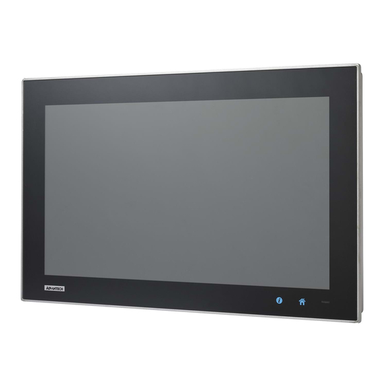
- Page 1 User Manual PPC-4211W Intel® Core i processor based microcomputer, with 21.5" color TFT LCD display...
- Page 2 No part of this manual may be reproduced, copied, translated or transmitted in any form or by any means without the prior written permission of Advantech Co., Ltd. Information provided in this manual is intended to be accurate and reliable. How- ever, Advantech Co., Ltd.
-
Page 3: Declaration Of Conformity
This product has passed the CE test for environmental specifications when shielded cables are used for external wiring. We recommend the use of shielded cables. This kind of cable is available from Advantech. Please contact your local supplier for ordering information. -
Page 4: Safety Instructions
The sound pressure level at the operator's position according to IEC 704-1:1982 is no more than 70 dB (A). DISCLAIMER: This set of instructions is given according to IEC 704-1. Advantech disclaims all responsibility for the accuracy of any statements contained herein. -
Page 5: Battery Information
Battery Information Batteries, battery packs and accumulators should not be disposed of as unsorted household waste. Please use the public collection system to return, recycle, or treat them in compliance with the local regulations. PPC-4211W User Manual... - Page 6 PPC-4211W User Manual...
-
Page 7: Table Of Contents
Environment Specifications............3 1.2.5 Certification Specifications............3 1.2.6 IP ....................3 Dimensions ....................4 Figure 1.1 PPC-4211W dimensions ..........4 Chapter System Installation & Setup ....5 Quick Start Guide..................6 Figure 2.1 Front panel ..............6 Figure 2.2 Side view ..............6 Figure 2.3 Location of I/O interfaces.......... - Page 8 Install Divers ................... 26 BIOS Setup ..................... 26 4.2.1 Enter BIOS.................. 26 4.2.2 Display Brightness Adjustment ........... 27 4.2.3 COM5 Mode Selection (RS422/485) .......... 28 4.2.4 Wake Up by LAN ................ 29 4.2.5 RAID Installation ................. 32 PPC-4211W User Manual viii...
-
Page 9: Chapter 1 General Information
Chapter General Information This chapter gives background information on the PPC-4211W panel PC. Sections include: Introduction Specifications Dimensions... -
Page 10: Introduction
Introduction The PPC-4211W is a new generation Panel PC with WXGA (1920 x 1080) screen. The system is equipped with a high performance Intel Core i CPU and with a high efficiency fanless thermal design the heat is easily dissipated. This gives HMI a big step forward in consolidating performance and reliability in one system. -
Page 11: Power Specifications
CB, CCC, UL 1.2.6 IP Front Panel IP Grade IP65 Note 1: PPC-4211W's power test conditions are as follows: Test Software Test Configuration Test System Memory: Transcend DDR3L 1600 SODIMM 8 GB x 1 HDD: Seageat 500G 2.5”x 2 Burn-in 7.0 Win7(64bit) IO: COM Port RS232 loopback x4, USB3.0 device x4,... -
Page 12: Dimensions
63.80 558.40 7.50 41.70 Ø100 Ø75 550.30 Figure 1.1 PPC-4211W dimensions Note! Supports VESA 100 x 100mm & 75 x 75mm; please use M4 screw, 6 mm depth (maximum). Use suitable mounting apparatus to avoid risk of injury. PPC-4211W User Manual... -
Page 13: Chapter 2 System Installation & Setup
Chapter System Installation & Setup Sections include: Quick Installation Guide Installation Procedures Installing Memory Installing HDD Installing Mini SATA Installing Wireless LAN Installing Expansion Card AT/ATX Function Switch Grounding Installation Hook Installation ... -
Page 14: Quick Start Guide
I Key Home Key Power status indicator, off (S5): orange, on (S0): blue Figure 2.2 Side view Quick installation clip (two) Antenna hole (two) Panel Mount Bracket holes (twelve) Side USB 2.0 interface CPU cooler Speaker (two) PPC-4211W User Manual... -
Page 15: Figure 2.3 Location Of I/O Interfaces
G: 4 x COM RS232 H: DC power(12-32 V) I: 1 x COM RS422/485 J: PCI/PCIE x4 Expansion slot (refer to Fig 2.4) K: Grounding screw (refer to Fig 2.5) Figure 2.4 PCI/PCIe expansion slot Figure 2.5 Grounding screw PPC-4211W User Manual... -
Page 16: Installation Procedures
Connecting the Keyboard and Mouse Connect the keyboard and mouse to panel PC’s I/O interfaces. 2.2.3 Power ON The power button is located in the right bottom side of the panel PC. Note! Power cable and adapter are optional. PPC-4211W User Manual... -
Page 17: Install Memory Card
Take out the black and gray thermal grease from the accessary box (as indicated in Figure 2.12). Attach the CPU heatsink after the grease is applied. Figure 2.11 Figure 2.12 Note! CPU cooler pad surface is isolated by anodization treatment to avoid static electricity (CPU contact side excluded). PPC-4211W User Manual... -
Page 18: Installing The Hdd
HDD and then fix the strength-plate (8 screws will be needed if using two HDDs). Lock the HDD bracket, and connect the HDD cable to the mainboard. (See Fig 2.18) Figure 2.13 Figure 2.14 Figure 2.15 Figure 2.16 Figure 2.17 Figure 2.18 PPC-4211W User Manual... -
Page 19: Installing Mini Sata
(See Fig 2.19) Plug the MiniSATA into the mainboard interface, and remove the 2 M2.5x4 screws from the accessory box to fix it (See Fig 2.20). Return the rear cover and strength-plate. Figure 2.19 Figure 2.20 PPC-4211W User Manual... -
Page 20: Installing Wireless Lan Card
Remove the two plugs on the left and right sides of the rear cover. (See Fig 2.24) Return the rear cover and install the antenna of the wireless LAN card module. (See Fig 2.25) Note! For wireless LAN card module, you can choose Advantech Product: (Part No. PPC-4211W-WLANE). Figure 2.23 Figure 2.24 PPC-4211W User Manual... -
Page 21: Figure 2.25
Figure 2.25 PPC-4211W User Manual... -
Page 22: Installing The Riser Card
Figure 2.26 Figure 2.27 Figure 2.28 Figure 2.29 AT/ATX Function Switch The switch is built in to the machine. Use it to choose AT/ATX functions without removing the rear cover. Figure 2.30 ATX mode Figure 2.31 AT mode PPC-4211W User Manual... -
Page 23: Grounding Installation
Loosen the screws, remove down the plastic cover, plug in the grounding cable, and then fix the screws. (See Fig 2.32 ~ Fig 2.35) Figure 2.32 Figure 2.33 Figure 2.34 Figure 2.35 Note! The grounding cable is not provided in the accessory box. PPC-4211W User Manual... -
Page 24: Hook Installation
Follow the figures below: Hook Put the machine into the carbinet, and prepare the hook. Install the hook into the hole to hold the machine as shown above Screw Secure the machine by fastening the screws Figure 2.36 Hook Installation PPC-4211W User Manual... -
Page 25: Solo Quick Installation
Users can independently complete the panel wallmount installation by quick installa- tion Guide. Follow the procedures below: Loosen the two screws at the base, see the figure below. Push the machine into a gap in the wall, the spring hook will lock the machine into the wall. PPC-4211W User Manual... - Page 26 Section 2.10 “Hook Installation”. Note! It is recommend that the mount thickness is smaller than 2 mm (0.079”) according to quick installation guide. For other situations, the recom- mended thickness is less than 6 mm (0.236”). PPC-4211W User Manual...
-
Page 27: Jumper Configuration
Chapter Jumper Configuration Sections include: Jumper & Connectors External COM Port Pin Defini- tion... -
Page 28: Figure 3.1 Pcm-8209 Front View
Figure 3.1 PCM-8209 front view SW1 Panel Resolution Selection Setting Function 1000 for 15.6" LCD 1110 for 21.5" LCD CN20 COM1/COM2 RI Type Select Description For COM1/COM2 select RI Voltage mode Setting Function (1-3) (2-4) (default) (3-5) (4-6) (7-9) (8-10) PPC-4211W User Manual... - Page 29 CN17 clean CMOS Setting Function (1-2) Clear CMOS (2-3) Keep CMOS (default) SW2 ATX/AT Mode Selection Pin Name ATX Power(default) AT Power CN15 GPIO Pin Name GPIO4 GPIO0 GPIO5 GPIO1 GPIO6 GPIO2 GPIO7 GPIO3 PPC-4211W User Manual...
-
Page 30: External Com Port Pin Definition
COM4 doesn’t support RING function. COM1-4: COM1 / COM2 COM3 / COM4 RING or 5V/12V output RING (Only COM3) Pin9 is set as RI signal in COM port by default, and could be set as 5V/12V output by Jumper PPC-4211W User Manual... - Page 31 (1) 8 data bits + 1 parity bit + 1stop bit (2) 8 data bits + 1 parity bit + 2 stop bits (3) 8 data bits + 2 stop bits PPC-4211W User Manual...
- Page 32 PPC-4211W User Manual...
-
Page 33: Software Configuration
Chapter Software Configuration Sections include: Installing Drivers BIOS Setup Program... -
Page 34: Install Divers
ROM may not be the latest version, if needed, find it at: http://www.advantech.com/ BIOS Setup 4.2.1 Enter BIOS Start the computer and press the “Delete” key to enter BIOS. Press “F4” to save and exit after any configuration, or the configuration won't be saved in BIOS. PPC-4211W User Manual... -
Page 35: Display Brightness Adjustment
Select “Brightness Manual Control” under “Brightness Control”, and there will be six [6] options: Note! If you want to adjust brightness through AP in the OS, it will keep AP configuration mainly, and BIOS configuration will not be saved. PPC-4211W User Manual... -
Page 36: Com5 Mode Selection (Rs422/485)
4.2.3 COM5 Mode Selection (RS422/485) Select “Super IO Configuration” under “Advanced”. Select “Serial Port 5 Configuration” and then select the operation mode of COM5 by "Serial Port5 Mode". PPC-4211W User Manual... -
Page 37: Wake Up By Lan
4.2.4 Wake Up by LAN Select “ACPI Settings” under “Advanced”. Set “Wake On By LAN or RI” as “Enabled”. PPC-4211W User Manual... - Page 38 Then save the configuration and exit the OS. Right click “Computer” and click “Manage”, then open “Computer Manage- ment”. PPC-4211W User Manual...
- Page 39 Click “Network adapters” in “Device Management”, then right click and select the needed LAN port, then select “Properties” and open “Intel(R) Ethernet”. Select “Work On Magic Packet”, “Work On Pattern Match” and “Work On Magic Packet From Power Off State” under “Power Management”. PPC-4211W User Manual...
-
Page 40: Raid Installation
4.2.5 RAID Installation Enter BIOS when boot up, and click “SATA Configuration” under Advanced. Set “SATA Mode Selection” as “RAID”, then save and exit. PPC-4211W User Manual... - Page 41 Press “Ctrl + I” to enter RAID configuration utility when entering the second start-up screen. Enter “Create RAID Volume”. PPC-4211W User Manual...
- Page 42 Input “Name” and select “RAID Level”, and then save and exit “Create Volume” menu. Click “Exit”, the device will start the normal RAID installation. PPC-4211W User Manual...
- Page 43 Take out the OS setup disk when you see this screen, then insert the driver disk and click “Load driver”. Select RAID driver folder and click “OK”. PPC-4211W User Manual...
- Page 44 Click “Next”. Replace the driver disk with system setup disk after installation of RAID driver is finished, then click “Next” to return the normal system installation. PPC-4211W User Manual...
- Page 45 After installing all the drivers, click the “SetupRST.exe” in the driver folder. Click the icon in the lower-right corner of the screen to check the working status of RAID Volume. PPC-4211W User Manual...
- Page 46 Click the message box to check details of the problem. At this time, you will need to turn off the computer to change the failed HDD. After entering the system, click “Rebuild to another disk” to back up the system to the new hard disk. PPC-4211W User Manual...
- Page 47 When the rebuilding status shows 100%, system backup is complete and RAID 1 function will work again. PPC-4211W User Manual...
- Page 48 No part of this publication may be reproduced in any form or by any means, electronic, photocopying, recording or otherwise, without prior written permis- sion of the publisher. All brand and product names are trademarks or registered trademarks of their respective companies. © Advantech Co., Ltd. 2014...
Need help?
Do you have a question about the PPC-4211W and is the answer not in the manual?
Questions and answers