Jandy AquaLink RS Installation Manual
All button and onetouch control panels
Hide thumbs
Also See for AquaLink RS:
- Owner's manual (68 pages) ,
- Installation manual (40 pages) ,
- Troubleshooting manual (28 pages)
Table of Contents
Advertisement
Advertisement
Table of Contents

Related Manuals for Jandy AquaLink RS


Summary of Contents for Jandy AquaLink RS
- Page 1 ™ A ll Button and O neTouch C ontrol Panels...
- Page 2 Important Safety Precautions When installing and using this electrical equipment, these basic safety precautions should always be followed: READ AND FOLLOW ALL INSTRUCTIONS LIRE LA NOTICE TECHNIQUE. DANGER - to reduce the risk of injury, do not permit children to use this product unless they are closely supervised at all times.
-
Page 3: Table Of Contents
Table of Contents Safety Precautions Safety Precautions Specifications Dimensions Table of Contents System Overview Controller Package Power Center Options and Accessories Other Options Specialty Boards TeleLink Kit Surge Protection Kit Basic Plumbing Standard Plumbing for Pool and Spa Non-Booster Pump Pressure-Side Pool Cleaner Plumbing Booster Pump Pool Cleaner Plumbing Solar System Plumbing 8-11... -
Page 4: System Overview
System Overview *Not Available in CE Models... -
Page 5: Other Options
Other Options Sp ec ia lty Bo a rd s JVA R e la y In terloc k Bo a rd A ux ilia ry /JVA Re la y B o a rd Plug in JVA Filter Pum p (N ormally Trans forme r F I LT E R P U M P JV A... -
Page 6: Basic Plumbing
Controller, water circulation switches between pool and spa. Consult the JVA Installation Manual to ensure that the Jandy Valve Actuators are "in synch" and rotate properly. Please also note that if you have a pool only or a spa only,... -
Page 7: Booster Pump Pool Cleaner Plumbing
Seal Valve to provide drain down. Plumb in a solar booster pump if needed. NOTE: A Jandy (10K) Solar Sensor will be needed for solar system control. The sensor should be located near the solar panels and connected to the Power Center by 18 AWG wire. -
Page 8: Power Center Connection
All electrical equipment, except for the Four Function Switch, must be five feet or more from pool /spa and comply with all national, state and local codes. If using a Jandy Power Center without built-in breaker compartment, install electrical supply panel with separate breakers for each load. - Page 9 Power Center Connection - High Voltage *This diagram shows wiring for a standard relay. For light dimming or two-speed operation, follow wiring instructions included with those relays.
- Page 10 Power Center Connection - Low Voltage If connecting more than 2 items to the RS Power Center red 4 pin terminal bar, a multiplex PCB is required.
- Page 11 Do not disconnect high limit or pressure switches. NOTE: For connection to specific heater brands, please see the Heater Connection Installation Guidelines. For Laars LX Heater (If the AquaLink RS has Rev. "I" or higher the LX must have a microprocessor with Rev. "C-10" or higher) a.
-
Page 12: Auxiliary Power Centers
Note: If you are installing more than one accessory board, order and use a Jandy Multiplex Kit (p/n 6584). Never put more than two wires into each of the pins of the terminal bar. Use the multiplex board whenever more than two of the 4-wire cabes... - Page 13 All Button Control Panel Installation Prepare Control Panel Site. With the aid of the homeowner, find the best location for the Control Panel. To ensure the Control Panel is level, hold the Mounting Bracket against the wall and mark the top inside of the upper right screw hole. Using this mark as a guide, place a level against the mounting wall and draw a horizontal line 4¼...
- Page 14 "double-up" wires in the red terminal bars, but never put more than two wires into each pin of the terminal bars. If you need to join more than two of the 4-wire cables, order and install Jandy Part # 6584...
-
Page 15: Dip Switch Settings
DIP #3 ON - - - - - — A UX 3 CONTROLS SPA SPILLOVER (OPERATES WITH POOL/SPA COMBINATION UNITS): Turn this switch on, and when the AUX 3 button on the AquaLink RS Controller (or Spa Side Switch) is pressed, the Return Valve Actuator will rotate to spa circulation. -
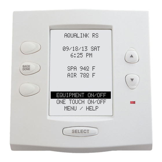
Page 16: Onetouch Control Panel Installation
OneTouch Control Panel Installation This document gives instructions for installing the Jandy ® AquaLink RS OneTouch Indoor Control Panel (surface Upper Flange and flush mount). The instructions must be followed exactly. Read through the instructions completely before starting the procedure. -
Page 17: Flush Mount
Buttons Flush Mount Surface Mount Figure 5. AquaLink RS One Touch (surface and flush mount) Assembly Place the PCB w/LCD and buttons back into the box. Be sure the rubber washer is between the screw head and the Reset Button PCB. - Page 18 OneTouch Installation Templates Template 1- Flush Mount 4.03" WARNING Do not cut 4.03" the sheetrock any bigger than the template. Figure 7. Flush Mount Template Template 2- Surface Mount Drill Thru 3/16" (3) Places Drill Thru 1¼” Figure 8. Surface Mount Template...
-
Page 19: Basic Programming
ENTER. Default Time - 1:00 P.M. Default Day - MONDAY Depending on the age of the AquaLink RS, the following items can be Default Date - 01/31/00 found either in the Main Menu or in a Sub Menu under SETUP: Set the Temperature. -
Page 20: Resetting The System
For example, to CANCEL A DIMMER, press the CANCEL button; use the forward and back buttons to advance to DIMMERS and press ENTER. The AquaLink RS display will prompt to select an Aux. - Page 21 OneTouch Control Panel Programming and System Defaults Basic Programming. KEY HELP To set a particular piece of equipment to turn on and off at PAGE UP predetermined times, highlight EQUIPMENT ON/OFF and press select. To highlight an item, use the up or down buttons. Use the SELECT BACK button to turn the equipment on or off.
- Page 22 Special Note to "Start-up Person": The AquaLink RS allows you two options for operating the pool equipment for the first day of operation: Option #1 - Once all programming of equipment is completed, go to the Power Center Service Switch. Push the Switch three times which moves from "AUTO"...
- Page 23 Four Function Spa Side Remote Provisions The Four Function Spa Side Remote is a double insulated, submersible device which is ETL listed (to UL Standard 1563) for installation at the water’s edge. It is typically installed at the tile-line of the spa wall, or in the deck within arm’s reach of the spa.
- Page 24 Install a reducer to the end of the 6" piece of pipe and run a ½” or ¾” electrical conduit underground from the reducer to the AquaLink RS Power Center location (see page 10 of the AquaLink RS Installation Manual for further details on the Power Center).
- Page 25 Install a reducer to the end of the 6" piece of pipe and run ½” Control or ¾” electrical conduit underground from the reducer to the AquaLink RS Power Center location (see page 10 of the “O” rings AquaLink RS Installation Manual for further details on the Power 1½"...
-
Page 26: Aquarite Chlorine Generator Installation
Chlorine Generator Installation Installation Instructions: The Jandy AquaLink RS and AquaRite use a 4-wire connection to communicate and can be wired up to 500' apart. Any outdoor rated 4 conductor cable can be used. Locate appropriate screw terminals on the circuit board according to the diagram below (screw terminals are removable to aid in installation). - Page 27 ® AquaLink RS Troubleshooting Quick Check List Symptom Problem Possible Solution Power Center override Power supply problem. Check connection of the outside switches operate when in two wires (red and green) of the Service or Time Out Mode, but four conductor cable. the Controller is completely If wired correctly, check the volt- dead (no lights on, no display).
- Page 28 Cleaner JVA to an auxiliary (Rev F or older). Either install the adjustable Normal operation when a Dual Model is one of the AquaLink RS freeze sensor, or wait 24 hours Equipment AquaLink RS is Dual Equipment, message scrolls and this message will go away.
-
Page 29: Installation Guidelines
1. Connect two 18 gauge wires, designed for use in hot environments, to the proper terminals on the Heater Terminal Bar. 2. Bring two heater wires from the AquaLink RS P.C. Board over to the heater and wire in series with the heater circuitry as if you were wiring a fireman's switch or heater delay. -
Page 30: Aqualink
1. Remove the heater service door. 2. Separate the black wire (common) from each other (see diagram at right). 3. Connect the wires from the AquaLink RS P.C. Board to the two black wires as shown. The violet and red wires remain unused. - Page 31 All Button Control Panel Cancel Flow Chart CANCEL SOME Select Device PROGRAMS To Be Canceled CANCEL ALL Press ENTER to Remove All Devices Except FRZ PROTECT Pump from Freeze Protection or Cancel to Abort Select AUX to Label Removed AUX LABEL Remove Label From Press ENTER to Select AUX to...
- Page 32 All Button Control Panel Menu Flow Chart On All Days PROGRAMS Select On Weekends PROGRAM Equipment TEMP SET On Weekdays Back Light SPA SWITCH Basement Light On Specific Day Beach Light REVIEW SPA LINK Bedroom Light Bug Light PROTECT Cabana Light POOL TEMP Color Wheel Light SET TEMP...
- Page 33 OneTouch Control Panel Menu Flow Chart O N ETO UC H 1 O N ETO UC H O N/O FF O N ETO UC H 2 O FF O N ETO UC H 3 S elect E Q UIPM E NT O N/O FF E quipme nt O FF K EY S...
- Page 34 Power Center Wiring Diagram R e tu rn S o la r E le c t. J V A J V A H e a te r In ta k e C le ane r S o lar J V A P u m p 4 3 2 1 6 5 4 3 2 1...
- Page 35 Notes...
- Page 36 Listed 4J39 Swimming Pools & Spa Controllers 6000 Condor Dr., Moorpark, CA, USA, 93021 • 707.776.8200 FAX 707.763.7785 480 S. Service Road West, Oakville, Ontario, Canada L6K 2H4 • 905.844.8233 FAX 905.844.2635 Litho in USA © Water Pik Technologies, Inc. Sheet #6594, Rev E, 9/01 For Technical Support call 707-776-8200, ext.
Need help?
Do you have a question about the AquaLink RS and is the answer not in the manual?
Questions and answers