Jandy AquaLink RS6 Troubleshooting Manual
Pool spa combination systems
pool spa only systems
dual equipment systems
Hide thumbs
Also See for AquaLink RS6:
- Installation manual (40 pages) ,
- Installation manual (16 pages)
Table of Contents
Advertisement
Troubleshooting Data
Troubleshooting Manual
AquaLink
All Button and
OneTouch
Control Systems
Pool/Spa Combination Systems
Pool/Spa Only Systems
Dual Equipment Systems
FOR YOUR SAFETY - This product must be installed and serviced by a pro fes sion al pool/
spa service technician. The procedures in this manual must be followed ex act ly. Failure to
follow warning notices and instructions may result in property damage, serious injury, or
death.
RS
®
™
WARNING
Advertisement
Table of Contents
Troubleshooting

Related Manuals for Jandy AquaLink RS6


Summary of Contents for Jandy AquaLink RS6
- Page 1 Troubleshooting Data Troubleshooting Manual AquaLink ® All Button and OneTouch ™ Control Systems Pool/Spa Combination Systems Pool/Spa Only Systems Dual Equipment Systems WARNING FOR YOUR SAFETY - This product must be installed and serviced by a pro fes sion al pool/ spa service technician.
- Page 2 Page 2...
-
Page 3: Table Of Contents
DIP Switches ............19 Water Temperature Sensor ......21 3 HP Relay ............23 Two Speed Relay ..........25 Light Dimming Relay ........27 Section 6. Jandy Valve Actuator ....29 Operation ............29 Section 7. Troubleshooting ......31 Quick Check List ..........31 Controller Inoperable, Display Blank ....33 All Lights Lit on Controller ........34... -
Page 4: Section 1. Important Safety Instructions
Page 4 Section 1. Important Safety Instructions READ AND FOLLOW ALL INSTRUCTIONS Lire la notice technique. All electrical work must be performed by a licensed electrician and conform to all national, state, and local codes. When installing and using this electrical equipment, basic safety precautions should always be followed, including the following: DANGER To reduce the risk of injury, do not remove the suction fittings of your spa or hot tub. - Page 5 Page 5 WARNING People with infectious diseases should not use a spa or hot tub. To avoid injury, exercise care when entering or exiting the spa or hot tub. Do not use drugs or alcohol before or during the use of a spa or hot tub to avoid unconsciousness and possible drowning.
-
Page 6: Section 2. Control Panel Overview
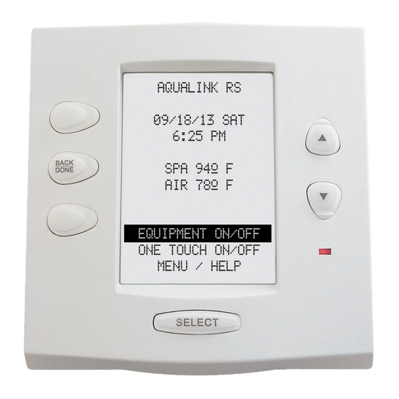
Page 6 Section 2. Control Panel Overview Indoor Control Panel The indoor control panel serves as a means of turning equipment on and off, entering programs to run equipment automatically at selected times, and displaying what is going on in the rest of the system. Programs (and other information entered through the controller) are stored in a memory chip on the power center board, even during a power interruption (however long). - Page 7 Page 7 Figure 1. All Button Controller (Front View) Jumpers for Display Module Multiple Controllers Controller 1 Controller 3 Controller 4 Controller 2 Jumper Settings for Micro Controller Multiple Controllers Figure 2. All Button Controller (Back View) Figure 3. OneTouch Controller (Front View) Reset Switch* Page Up/...
-
Page 8: Section 3. Controller
Page 8 Section 3. Controller Diagnostics The AquaLink system has an internal self-checking process, which can display its current status on the indoor control panel. Use the following steps to get to this "diagnostics" information: 1. All Button: Use the buttons along the lower left side of the controller. a. - Page 9 Page 9 Possible Online As Shown in Possible Unit Unit Order* Earliest PPD Devices Diagnostics While Numbers Important? Revision Usable Online All Button CONTROL PANEL 1,2,3,4 AquaLink PC CONTROL PANEL 4 Yes** OneTouch ONETOUCH 1,2,3,4 Wireless ONETOUCH 1,2,3,4 OneTouch*** Serial Adapter SERIAL ADAPTR 1,2, PHASTLink Serial...
-
Page 10: Controller Troubleshooting
If the secondary voltage is 24 to 28 VAC, turn off the power. e. Remove the fuse from its holder and do a continuity test. If there is no continuity, unplug all the Jandy Valve Actuators (JVAs), replace the fuse (3.15 amp), and turn on the power. If the fuse blows with all JVAs unplugged, the circuit board is damaged and needs to be replaced. - Page 11 Page 11 Check for broken or loose wires on terminals 1 and 4 Green (red and green) of the red Wire Wire 4-pin terminal bar. 4 3 2 1 4 3 2 1 6 5 4 3 2 1 10 9 8 7 6 5 4 3 2 1 RS6 &...
- Page 12 Page 12 3.2.2 Control Not Communicating with Power Center PCB The following conditions indicate that the control is not communicating with the power center PCB: 1. All Button Control: All the circuit LEDs are illuminated and the display is locked on a part number and revision letter.
-
Page 13: Heater Operation
Page 13 Heater Operation The pool and spa heater LED and the solar LED are two-color LEDs. Green indicates the heater is enabled but not on. Red indicates the signal to the heater relay is being sent. A heater or solar LED will remain green for the following reasons: 1. -
Page 14: Section 4. Power Center
Page 14 Section 4. Power Center Overview The power center PCB is the true brain of the system. The micro-controller on the PCB is constantly sending signals through the communication wires to the control panel and polling the system to determine which circuits should be on and which should be off. -
Page 15: Power Center Troubleshooting
Page 15 Power Center Troubleshooting 4.2.1 Loss of Power Check the power center transformer for the proper voltage. 1. Disconnect the transformer from the power center PCB. Check the voltage on the secondary transformer (the two (2) outside yellow wires). The two (2) outside wires provide the 24 to 28 VAC to the PCB. 2. -
Page 16: Main Power Center Pcb
Page 16 Main Power Center PCB 4.3.1 PCB Circuit Layout 1. JVA Relays (K2 - K5) 2. Low Voltage Heater Relay 3. 3.15 amp fuse. Fuse will blow to protect the transformer when there is a short circuit in the JVA(s) or the circuit board driver chip is damaged. - Page 17 Page 17 4.3.2 PCB Voltages 1. From Power Center to Controller, between terminals one (1) and four (4) of the two (2) red terminal blocks = 8 to 10 VDC. 2. To JVA 2444 = 24 to 28 VAC*. 3. To Relay Coils = 24 to 32 VDC*. 4.
-
Page 18: Section 5. Auxiliary Power Center
Page 18 Section 5. Auxiliary Power Center Overview An auxiliary power center provides control for systems that need to run more relays (and/or JVAs) than can be handled by the main power center. The main one is still the central "brain" of the system; it sends control signals to the auxiliary power center PCB through the 4-wire bus (red connector). -
Page 19: Dip Switches
Page 19 DIP Switches All DIP switches are located on the left side of the power center bezel. To change a setting, turn off the power and move the approprate switch from left (OFF) to right (ON). 4 3 2 1 4 3 2 1 6 5 4 3 2 1 10 9 8 7 6 5 4 3 2 1... - Page 20 Page 20 DIP Switch # Aux. 1 = Any equipment Aux. 1 = Pool cleaner Aux. 2 = Any equipment Aux. 2 = Low speed for a two speed fi lter pump. Filter pump circuit becomes high speed. Aux. 3 = Any equipment Aux.
-
Page 21: Water Temperature Sensor
Page 21 Water Temperature Sensor 5.3.1 Troubleshooting When the Power Center PCB is put in Service or Time Out Mode, the thermostat setting will automatically be switched to 104° F for testing. If the heater circuit is activated and the water heater temperature is less than 104° F, the LED above the heater button should turn on. - Page 22 Page 22 4 3 2 1 4 3 2 1 6 5 4 3 2 1 10 9 8 7 6 5 4 3 2 1 RS6 & RS8 ONLY RS8 ONLY POOL MODE RESET SPA MODE AUTO SPA DRAIN SERVICE HEATER SOLAR...
-
Page 23: Hp Relay
Page 23 3 HP Relay 5.4.1 Operation 1. A standard 3 HP Relay's coil is supplied with 24 VDC from the power center PCB via one (1) of the driver chips. When 24 VDC is received by the relay's coil wires, it closes the contacts that complete the circuit to turn on the equipment (i.e., power supplied to Line 1 goes out Load 1 to the equipment). - Page 24 Page 24 4 3 2 1 4 3 2 1 6 5 4 3 2 1 10 9 8 7 6 5 4 3 2 1 RS6 & RS8 ONLY RS8 ONLY RESET POOL MODE AUTO SPA MODE SPA DRAIN SERVICE HEATER SOLAR...
-
Page 25: Two Speed Relay
Page 25 Two Speed Relay 5.5.1 Operation The two speed relay operates in conjunction with a standard relay to operate a two speed pump/motor. The standard relay is the on/off relay and the two speed relay is the switching relay. Activating the relay coil for the standard relay will complete the contact circuit between Line 1 and the motor common, Line 2 and the two speed relay common. - Page 26 Page 26 4 3 2 1 4 3 2 1 6 5 4 3 2 1 10 9 8 7 6 5 4 3 2 1 RS6 & RS8 ONLY RS8 ONLY RESET POOL MODE AUTO SPA MODE SPA DRAIN SERVICE HEATER SOLAR...
-
Page 27: Light Dimming Relay
Page 27 Light Dimming Relay 5.6.1 Operation The controller signals the light dimming relay to turn "fully on", "partially dimmed", or "completely off" by sending a specifi c number of pulses in a set period of time to the light dimming relay. The circuitry of the light dimming relay, which requires 120 VAC to operate, interprets the number and timing of pulses to determine whether the light should be on, off, or dimmed. - Page 28 Page 28 Specifi cations Voltage: 12 to 120 VAC Wattage: 1000 maximum Note: a maximum of four (4) light dimming relays can be installed in each power center. Note A Standard Relay can be mounted (piggybacked) on top of the Dimmer Relay to allow for a total of eight (8) Relays in Power Center.
-
Page 29: Section 6. Jandy Valve Actuator
Page 29 Section 6. Jandy Valve Actuator Operation One leg of a 24 VAC transformer secondary supplies voltage to the common terminal of a SPDT (single-pole, double- throw) relay. The N.C. (normally closed) terminal of that relay is connected to the red wire of the JVA cord, and the N.O. - Page 30 Page 30 Figure 23. JVA Internal Wiring...
-
Page 31: Section 7. Troubleshooting
Page 31 Section 7. Troubleshooting Quick Check List Symptom Problem Possible Solution Power Center override switches Mis-wired four (4) conductor wires. The wire polarity is incorrect operate when in Service or Time Broken four (4) conductor wires. (Red +, Green -) Out Mode, but the Controller is Broken red or green wire. - Page 32 Page 32 Symptom Problem Possible Solution System sometimes does not run pro- Power outage with dead battery. At the Controller, check battery grammed on and off times. level. With software level Rev. F or newer, battery status is located in Diagnostics section of System Setup Menu One button on the Spa Side Remote...
-
Page 33: Controller Inoperable, Display Blank
Page 33 Controller Inoperable, Display Blank Go to the Control- Controller PCB ler and measure will need to be the voltage be- replaced. Check voltage tween the same on red terminal two terminals. Is bar between the Wires are broken the voltage 8 to 10 outside two ter- or in the wrong... -
Page 34: All Lights Lit On Controller
Page 34 All Lights Lit on Controller Correct the wiring prob- lem. Carefully recheck all four (4) conductor wires for breaks or poor connections. Especially the black Recheck the jumpers on and yellow wires. Are these wires the Controllers. Each broken or wired wrong? Controller jumper must be set differently so each... -
Page 35: Some Controller Buttons Do Not Operate
(LEDs fi rmware chip. for those buttons Does the Part# don't light). for fi rmware chip match the model of Contact Jandy for cor- AquaLink RS? See rect fi rmware chip. chart below. Part # Part # Part # Rev. -
Page 36: Three Amp Fuse Keeps Failing
Page 36 Three Amp Fuse Keeps Failing Replace Power Center PCB. Turn off power and remove both relay driver chips. Replace the fuse and turn on power. Does fuse fail Replace both relay again? driver chips. Disconnect all JVAs and Three Amp Fuse on replace fuse. -
Page 37: Heater Doesn't Fire
Page 37 Heater Doesn't Fire NOTE: Before proceeding, check Sporadic operation can Controller display. If the display be traced to one or more reads "Shorted" or "Open" on loose connections, includ- Water Temperature Sensor, check ing those within the heater. Recheck heater the water temperature sensor Check all connections. -
Page 38: Section 8. Flow Charts
HEAT PUMP PRIORITY † ††† RETURN SYSTEM ENABLED PUMP LOCKOUT CLEANER SETUP DISABLED SOLAR ASSIGN JVAs JANDY LIGHT COLOR LIGHTS SAM/SAL LIGHT ASSIGN TO AUX DIMMERS** COLOR LOGIC GO BACK SELECT LOCATION DUSK CTRL SPA SWITCH** DURATION PACIFIC SPA LINK**... -
Page 39: All Button Menu Flow Chart
Page 39 All Button Menu Flow Chart ON ALL DAYS SELECT PROGRAM EQUIPMENT ON WEEKENDS PROGRAMS ON WEEKDAYS TEMP SET ON SPECIFIC DAY ALL OFF TIME REVIEW SPA SWITCH POOL TEMP SPA LINK SET TEMP SPA TEMP FRZ PROTECT MAINTAIN TEMP SET YEAR, DAY AUX LABELS SET TIME... -
Page 40: All Button Cancel Flow Chart
Page 40 All Button Cancel Flow Chart CANCEL SOME Select device to PROGRAMS be cancelled CANCEL ALL Press enter to remove all devices except pump from FRZ PROTECT freeze protection, or cancel to abort Select AUX to AUX LABEL Label removed remove label from CANCEL BUTTON Press enter to... -
Page 41: Section 9. Wiring Diagrams
4. After wiring, install panels over wiring compartments and keep Power Center door closed. 6000 Condor Drive • Moorpark, CA USA 930201 5. For technical information, call Jandy Pool Products, Inc. at 707-776-8200 ext. 260. 707.776.8200 • Fax 707.763.7785 Sheet #7192, Rev. H Litho in USA ©... -
Page 42: Aqualink Rs Dual Equipment
5. For indoor or outdoor use. 6000 Condor Drive • Moorpark, CA USA 93021 707.776.8200 • Fax 707.763.7785 For technical information, call Jandy Pool Products, Inc., at 707-776-8200, ext. 260. Litho in USA © Jandy Pool Products, Inc. 0711 CAUTION... -
Page 43: Aqualink Rs Auxiliary Power Center
Page 43 AquaLink RS Auxiliary Power Center To Power Center #1 Aux B 2 Aux B 4 (or Indoor Control Panel) JV A JV A Aux B 1 Aux B 3 JV A JV A 4 3 2 1 JV A S ockets (24 VA C output) Relay Socket s (24 VDC output) Relay Socket s (24 VDC output) -
Page 44: Section 10. Power Center Bezel
Page 44 Section 10. Power Center Bezel RESET RS6 & RS8 ONLY RS8 ONLY POOL MODE AUTO SPA MODE SERVICE SPA DRAIN HEATER SOLAR TIME OUT SPA FILL Pool/Spa Combination and Pool/Spa Only, Part # 6762 RESET AUTO SERVICE TIME OUT 6762 Dual Equipment, Part # 6782 RESET... - Page 45 Page 45 Notes...
- Page 46 Page 46 Notes...
- Page 47 Page 47 Notes...
- Page 48 DE grids, or cartridge elements; or damage caused by running the pump with insufficient quantities of water. LIMITATION OF LIABILITY: This is the only warranty given by Jandy Pool Products, Inc. No one is authorized to make any other warranties on behalf of Jandy Pool Products, Inc. THIS WARRANTY IS IN LIEU OF ALL OTHER WARRANTIES, EXPRESSED OR IMPLIED, INCLUDING BUT NOT LIMITED TO ANY IMPLIED WARRANTIES OF FITNESS FOR A PARTICULAR PURPOSE AND MERCHANTABILITY.
Need help?
Do you have a question about the AquaLink RS6 and is the answer not in the manual?
Questions and answers
how to test th econtrol center board