Jandy AquaLink RS Owner's Manual
Pda handheld remote - pool digital assistant pool/spa combination systems and pool only/spa only systems
Hide thumbs
Also See for AquaLink RS:
- Owner's manual (68 pages) ,
- Installation manual (40 pages) ,
- Troubleshooting manual (28 pages)
Table of Contents
Advertisement
Quick Links
Operation Data
Owner's Man u al
AquaLink
PDA - Pool Digital
Assistant
Pool/Spa Combination Systems and
Pool Only/Spa Only Systems
(Models PS4, PS6, PS8, P4, and P8)
Firmware Revision 4.1
FOR YOUR SAFETY: This product must be installed and serviced by a pro fes sion al pool/spa service
technician. The procedures in this manual must be followed ex act ly. Failure to follow warning notices
and instructions may result in property damage, serious injury, or death. Improper installation and/or
operation will void the warranty.
This device complies with part 15 of the FCC Rules. Operation is subject to the following two conditions: (1) This
device may not cause harmful interference, and (2) this device must accept any interference received, including
interference that may cause undesired operation.
NOTE: This equipment has been tested and found to comply with the limits for a Class B digital device, pursuant to
part 15 of the FCC Rules. These limits are designed to provide reasonable protection against harmful interference in
a residential installation. This equipment generates, uses and can radiate radio frequency energy and, if not installed
and used in accordance with the instructions, may cause harmful interference to radio communications. However,
there is no guarantee that interference will not occur in a particular installation. If this equipment does cause
harmful interference to radio or television reception, which can be determined by turning the equipment off and on,
the user is encouraged to try to correct the interference by one or more of the following measures:
•
Reorient or relocate the receiving antenna.
•
Increase the separation between the equipment and receiver.
•
Connect the equipment to an electrical source on a circuit different from that to which the receiver is connected.
•
Consult the dealer or an experienced radio/TV technician for help.
Modifi cations made to this equipment, which are not authorized by the manufacturer, may void the user's authority
to operate this equipment.
RS
®
WARNING
ATTENTION
Advertisement
Table of Contents

Subscribe to Our Youtube Channel
Related Manuals for Jandy AquaLink RS


Summary of Contents for Jandy AquaLink RS
- Page 1 Operation Data Owner's Man u al AquaLink ® PDA - Pool Digital Assistant Pool/Spa Combination Systems and Pool Only/Spa Only Systems (Models PS4, PS6, PS8, P4, and P8) Firmware Revision 4.1 WARNING FOR YOUR SAFETY: This product must be installed and serviced by a pro fes sion al pool/spa service technician.
-
Page 3: Table Of Contents
Page 3 Table of Contents Section 1. Important Safety Instructions ..4 Auto Shut-off Menu .......... 21 Backlight Menu ..........22 Section 2. Overview of the PDA Handheld Assign Hotkeys Menu ........22 Remote ..........6 5.10 System Setup Menu ........23 Basic Functions .......... -
Page 4: Section 1. Important Safety Instructions
Page 4 Section 1. Important Safety Instructions READ AND FOLLOW ALL INSTRUCTIONS LIRE LA NOTICE TECHNIQUE. All electrical work must be performed by a licensed electrician and conform to all national, state, and local codes. When installing and using this electrical equipment, basic safety precautions should always be followed, including the following: DANGER To reduce the risk of injury, do not remove the suction fittings of your spa or hot tub. -
Page 5: Save These Instructions
Page 5 WARNING People with infectious diseases should not use a spa or hot tub. To avoid injury, exercise care when entering or exiting the spa or hot tub. Do not use drugs or alcohol before or during the use of a spa or hot tub to avoid unconsciousness and possible drowning. -
Page 6: Section 2. Overview Of The Pda Handheld Remote
Page 6 Section 2. Overview of the PDA Handheld Remote This document gives in struc tions for operating the Jandy AquaLink RS PDA handheld remote. The in struc tions must ® be fol lowed exactly. Read through the instructions com plete ly before operating the equipment. -
Page 7: Battery Status
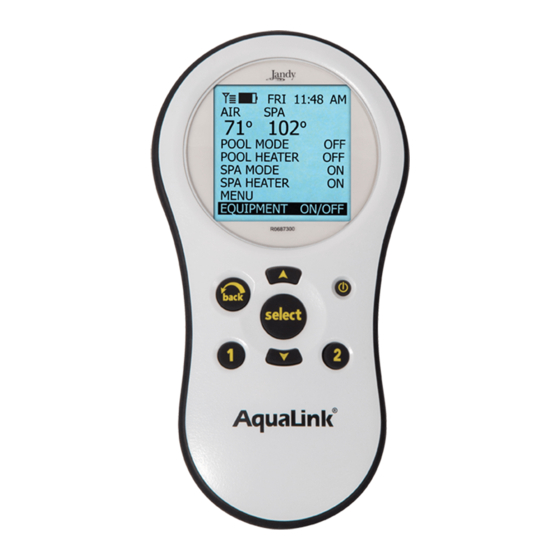
Page 7 2.3 Battery Status The Battery icon , located on the left corner of the display screen, indicates the status of the battery. The PDA Handheld Remote uses two (2) AA batteries. The batteries are located behind the cover on the back side of the Handheld Remote. -
Page 8: Section 3. Using The Equipment On/Off Menu
Page 8 Section 3. Using the Equipment On/Off Menu 3.1 Equipment On/Off Use this menu to manually turn a piece of equipment on or off. The ALL OFF mode will turn off equipment that has been turned on by any means (manual or pre-programmed). This includes any of the heater enables that were on (unless in use by the Maintain function). -
Page 9: Spa
Page 9 3.3 Spa The SPA mode switches water circulation from the pool to spa (pool/spa combination models only). Turning on the spa also activates the filter pump (after a delay for valve rotation) and deactivates the pool cleaner if it is on. The SPA mode must be on to display the spa temperature and/or to heat the spa. -
Page 10: Spa Heat
Page 10 3.5 Spa Heat The SPA HEAT enables the heater for the spa. The desired temperature can be set from the SET TEMP menu, or you can increase/decrease the temperature when enabling the heater. 3.5.1 To use Spa Heat Highlight SPA and press SELECT. -
Page 11: Solar Heat
Page 11 3.6 Solar Heat The SOLAR HEAT selection controls solar heating. A solar heating system and optional solar sensor are required for SOLAR HEAT selection to operate and must be part of the normal circulation system. 3.6.1 To use Solar Heat Highlight SOLAR HEAT and press SELECT. -
Page 12: Auxiliary Equipment
Page 12 3.7 Auxiliary Equipment The AUX modes control each of the auxiliary devices plus an extra AUX. To assign a different name to an auxiliary device, use the SYSTEM SETUP and LABEL AUX menus. NOTE Auxiliary devices are items or equipment such as pool and spa lights, waterfalls, or air blowers. 3.7.1 To turn an Auxiliary on or off Highlight EQUIPMENT ON/OFF and press SELECT. -
Page 13: Set Light Colors
Page 13 3.9 Set Light Colors NOTE This equipment may not be part of your system. Please check with your installer. The SET COLOR menu is used to set the color of a color light and then turn the light on. NOTE Prior to setting the color of the light, the light must be assigned and controlled by an auxiliary (for example, AUX 1). -
Page 14: Variable Speed Pump
Page 14 3.10 Variable Speed Pump NOTE This equipment may not be part of your system. Please check with your installer. The speed of a variable speed pump can be adjusted from the EQUIPMENT ON/OFF screen. In the example below the SPEED PRESET #3 is adjusted to 2750 RPM. -
Page 15: Section 4. Using The Equipment On/Off Model Specific Menus
Page 15 Section 4. Using the Equipment On/Off Model Specifi c Menus 4.1 TEMP1 (Pool or Spa Only) NOTE This equipment may not be part of your system. Please check with your installer. TEMP1 is the priority temperature. It must be set higher than TEMP2, and it overrides TEMP2 whenever it is enabled. -
Page 16: Two Speed Operation
Page 16 4.3 Two Speed Operation NOTE This equipment may not be part of your system. Please check with your installer. Optional TWO SPEED RELAY required. 4.3.1 Two Speed Manual Operation 1. For Pool and Spa Combination Units If your control is a POOL and SPA combination with a 2-speed fi ltration pump, the control will operate as follows: HIGH SPEED (Filter Pump) must be on before LOW SPEED. -
Page 17: Section 5. Using The Menus
Page 17 Section 5. Using the Menus 5.1 Service Menu In the HELP menu, you will find the SERVICE menu. The SERVICE menu gives you the phone number (if entered) for your local service company. See SERVICE INFO menu, under SYSTEM SETUP, to enter your local service company information. -
Page 18: Program Menu
Page 18 5.3 Program Menu The Program menu allows automatic on and off times for any equipment controlled by the AquaLink RS. You ® can program equipment to turn on or off all days, weekends, or weekdays. Each piece of equipment can be have a maximum of two programs per device. - Page 19 Page 19 5.3.2 Programming the Variable Speed Pump This section describes how to program a variable speed pump. A variable speed pump can be programmed to run at any one of its eight (8) speeds. If the variable speed pump is used for pool filtration, then it will be powered from the FILTER PUMP relay.
-
Page 20: Set Temperature Menu
Page 20 5.4 Set Temperature Menu The SET TEMP menu allows you to preset the pool and spa thermostats. NOTE For pool/spa combination systems, the default pool temperature is 80°F and the default spa temperature is 102°F. For pool only/spa only systems, the default TEMP1 temperature is 80°F and the default TEMP2 temperature is 60°F. 5.4.1 To set Pool/Spa Temperatures Highlight MENU and press SELECT, highlight SET TEMP and press SELECT. -
Page 21: Aquapure ® Menu
Page 21 5.6 AquaPure Menu ® NOTE This equipment may not be part of your system. Please check with your installer. AquaPure chlorine generator systems exclusively communicate with the AquaLink ® RS. The AquaLink ® RS PDA handheld remote will display % of chlorine output. This menu item will only appear when an AquaPure chlorine generator is connected to the AquaLink RS system. -
Page 22: Backlight Menu
Page 22 5.8 Backlight Menu The backlight can be turned on and off. Leaving the backlight turned off will extend the battery life. NOTE Backlight default setting is set to OFF. 5.8.1 To change the Backlight setting Highlight MENU and press SELECT. Highlight PDA OPTIONS and press SELECT. Highlight BACKLIGHT and press SELECT. -
Page 23: System Setup Menu
Page 23 5.10 System Setup Menu Check with installer before making changes to the SYSTEM SETUP. 5.10.1 To use the System Setup menu Highlight MENU and press SELECT, highlight SYSTEM SETUP and press SELECT. Use the UP/DOWN arrow keys to move the highlight bar up or down to move through the menus. Press SELECT on the highlighted item to move to the next screen. -
Page 24: Section 6. Using The System Setup Menu
Page 24 Section 6. Using the System Setup Menu 6.1 Label Auxiliary Menu The LABEL AUX menu allows custom naming of auxiliary equipment. For example, you can set the display to read YARD LIGHT instead of AUX 4. 6.1.1 To use the Label Auxiliary menu Highlight MENU and press SELECT. -
Page 25: Boost Setup Menu
Page 25 6.2 Boost Setup Menu Use this menu to adjust the number of hours or mode of Boost. NOTE The MODE selection is only available if the Power Center Bezel dip switch 3 is turned on (Spillover mode). If it is off, then only TIME is displayed. -
Page 26: Air Temperature Menu
Page 26 6.3.1 To use the Freeze Protection menu Highlight MENU and press SELECT, highlight SYSTEM SETUP and press SELECT, highlight FREEZE PROTECT and press SELECT. Use the UP/DOWN arrows keys to change the activation temperature. Once the temperature is set, use the SELECT button to move to the next screen to assign freeze protection to a selected piece of equipment. -
Page 27: Degrees C/F Menu
Page 27 6.5 Degrees C/F Menu The Degrees C/F menu allows you to change the AquaLink RS temperature display from Fahr en heit to Celsius or ® vice versa. When changing from Fahrenheit to Celsius you will have to re-enter the temperature settings. 6.5.1 To change the Temp readout Highlight MENU and press SELECT, highlight SYSTEM SETUP and press SELECT, highlight DEGREES C/F and press SELECT. -
Page 28: Solar Priority
Page 28 6.7 Solar Priority The Solar Priority menu allows the system to use Solar Heat primarily. If Solar Heat is no longer available, the system will automatically switch to the alternate heat source. 6.7.1 To use the Solar Priority menu Highlight MENU and press SELECT, highlight SYSTEM SETUP and press SELECT, highlight SOLAR PRIORITY and press SELECT. -
Page 29: Assign Jva Menu
Use the UP/DOWN arrow keys to highlight an auxiliary to be assigned to a color light, then press SELECT. “JC” will appear next to the AUX if a Jandy Colors has been assigned. “JL” will appear next to the AUX if a Jandy LED Light has been assigned."SL"... -
Page 30: Spa Side Switch Menu
Page 30 6.11 Spa Side Switch Menu The spa side switch menu allows you to define which equipment is controlled by the buttons on the optional spa side switch(es). Default settings are spa, spa heat, aux1 and aux2. You may want to write down your spa side switch button assignments so that you can label the buttons on the switch with the label pack provided. -
Page 31: Clear Memory Menu
Page 31 MAIN MENU SERVICE INFO SYSTEM SETUP TEMP CALIBRATE HELP SOLAR PRIORITY PROGRAM SERVICE CO. PUMP LOCKOUT SET TEMP SERVICE PHONE ASSIGN JVAs SET TIME COLOR LIGHTS PDA OPTIONS Select an entry SPA SWITCH SYSTEM SETUP to change, then SERVICE INFO press SELECT. -
Page 32: Heat Pump Menu
The VAR SPEED PUMP menu is used to select the variable speed pump type and to select the various pump settings. The user has the option to control one of four types of variable speed pumps, Jandy ePump DC, Jandy ePump... - Page 33 Page 33 6.15.2 To Set the Pump Application The PDA can control up to four (4) variable speed pumps. The default application setting for each pump is NOT INSTALLED. If the system is not going to control a variable speed pump then leave the application set to NOT INSTALLED.
- Page 34 6.15.4 To Set SCALE/MIN-MAX Parameters This screen allows the user to set a minimum and maximum speed or flow for the indicated pump. The SCALE setting is fixed to RPM for the Jandy ePump DC, Jandy ePump AC, and IntelliFlo ®...
- Page 35 Page 35 Preset 1: The default label for preset #1 is POOL. This label is tied to the pool filtration mode. Anytime the pool pump is supposed to turn on, this preset is selected. Preset 2: On combo systems, the default label for preset #2 is SPA. This label is tied to the spa filtration mode. Anytime the spa pump is supposed to turn on, this preset is selected.
- Page 36 Page 36 6.15.7 To re-label the Speed Preset Each of the eight (8) default speed presets has a label and each of those labels can be changed from the default value. In the SPEED SETTINGS menu, highlight LABEL SPEEDS and press SELECT. Use the UP/DOWN arrow keys to highlight the desired label, then press SELECT.
- Page 37 Page 37 6.15.9 To Set the Priming Speed Whenever the variable speed pump is turned on it will go into the priming mode for a predetermined amount of time (1-5 minutes). This menu allows for the priming speed to be adjusted. NOTE The priming parameters for the IntelliFlo are set at the pump.
-
Page 38: Section 7. Glossaries
Page 38 Section 7. Glossaries 7.1 Glossary of Safety Delays The fi lter pump turns off while valves rotate between pool and spa to prevent damage Pool/Spa Switching Filter Pump Delay - to the pool equipment. The valves take 35 seconds to rotate between pool and spa; the fi lter pump will activate as soon as the valves have fi... -
Page 39: Glossary Of Pda Handheld Remote Messages
Page 39 7.3 Glossary of PDA Handheld Remote Messages BATTERY is LOW - This message (located in DIAGNOSTICS under the MENU) indicates that the battery supplying power to the Power Center clock (in case of power outage) is low, and should be replaced. The battery is a standard 9V, and may be replaced by removing the battery door (marked on the Power Center - Power Center is located by the pool equipment). -
Page 40: Section 8. Pda Handheld Remote Menu Flow Chart
SETUP CLEANER DISABLED SOLAR ASSIGN JVAs COLOR LIGHTS SELECT LIGHT TYPE ASSIGN TO AUX SPA SWITCH SERVICE INFO JANDY EPUMP DC JANDY EPUMP AC CLEAR MEMORY HEAT MODE INTELLIFLO VF CHILL MODE † HEAT PUMP INTELLIFLO VS PUMP MODEL FILTRATION... -
Page 41: Section 9. General, Water Feature, And Light Aux Labels
Entry Heat Pump Equipment Heater Hi-E2 Fence High Speed Flood Home A/C Fountn Home Heat Front Jet Pump Garage Jandy Lite Garden Lamp Gazebo Low Speed Hall Mist House Music Kitchen Not Used (see note) Laminar Plsr Ozonator Left Pond... - Page 42 Page 42 NOTES...
- Page 43 Page 43 NOTES...
- Page 44 DE grids, or cartridge elements; or damage caused by running the pump with insufficient quantities of water. LIMITATION OF LIABILITY: This is the only warranty given by Jandy Pool Products, Inc. No one is authorized to make any other warranties on behalf of Jandy Pool Products, Inc. THIS WARRANTY IS IN LIEU OF ALL OTHER WARRANTIES, EXPRESSED OR IMPLIED, INCLUDING, BUT NOT LIMITED TO, ANY IMPLIED WARRANTIES OF FITNESS FOR A PARTICULAR PURPOSE AND MERCHANTABILITY.
Need help?
Do you have a question about the AquaLink RS and is the answer not in the manual?
Questions and answers
can't turn on by phone anymore
You may not be able to turn on your Jandy AquaLink RS by phone anymore due to weak signal strength between the PDA Handheld Remote and the Transceiver J-Box. Signal strength decreases with distance and can be further reduced by obstructions like walls. Additionally, if there is no power to the control panel, as mentioned, this would also prevent remote operation. You should check the power supply, fuse, transformer output, and ensure the panel is functioning.
This answer is automatically generated
My pool said it pumps is offline. How can I turn it on