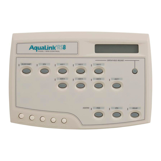
Jandy AquaLink RS Troubleshooting Manual
Electronic controllers
Hide thumbs
Also See for AquaLink RS:
- Owner's manual (68 pages) ,
- Installation manual (40 pages) ,
- Installation instructions (1 page)

Subscribe to Our Youtube Channel
Related Manuals for Jandy AquaLink RS


Summary of Contents for Jandy AquaLink RS
- Page 1 ® DISPLAY HOLD/RELEASE AUX 1 AUX 2 AUX 3 Troubleshooting M anual AUX 4 AUX 5 AUX 6 AUX 7 HEATERS POOL SOLAR MENU CANCEL BACK FORWARD ENTER...
-
Page 2: Table Of Contents
Light Dimming Relay ..... Jandy Valve Actuator ..... - Page 3 ® IM P O R TAN T: Plug in O ra nge 3-p in conn ecto r from Transform er to P.C .B. O P TIO N A L P o o l W a te r S e n so r F ilte r P u m p P o o l F ilte r...
-
Page 4: Controller
Supply Voltage: 10 VDC Operating Voltage: 5 VDC Circuit Activation: Serial Communication NOTE: A Jandy Service Controller (P.N. 7057) can be attached out at the Power Center, to review and/or change programs and equipment settings. R e se t S w itch... -
Page 5: Power Center
® Power Center Operation: The Power Center PCB is the true brain of the system. The micro-controller on the PCB is constantly sending signals through the communication wires to the Controller and polling the system to determine which circuits should be on and which should be off. - Page 6 ® DIP Switches Bezel and Power Center Board Jum per for Freeze Protection 24 VAC from w ith Solar on Dual Equipm ent M odels Secondary of Transform er 3 A m p Fuse Spare Aux U10 Socket U9 Socket Program m able Peripheral Device Relay D river C hips pry slots...
- Page 7 ® Operation: A Standard Relay's coil is supplied 24 VDC from the Power Center PCB via one of the two driver chips. When 24 VDC is received by the relay's coil wires, it closes the contacts that complete the circuit to turn on the equipment (i.e., power supplied to Line 1 goes out Load 1 to the equipment).
-
Page 8: Standard Relay
® Operation: The Two Speed Relay operates in conjunction with a Standard Relay to operate a two speed pump/motor. The Standard Relay is the On/Off relay and the Two Speed Relay is the switching relay. Activating the relay coil for the Standard Relay will complete the contact circuit between Line 1 and the motor common, and Line 2 and the Two Speed Relay's Common. -
Page 9: Light Dimming Relay
Relay Coil : 24 VDC Light Dim m ing Relay Installation Intructions - Jandy p/n 6587 or 6785 S ta nd a rd R e lay m a y b e p ig g yb a cked o n to p o f... - Page 10 ® Operation One leg of a 24 VAC transformer secondary supplies voltage to the common terminal of a SPDT (single-pole, double-throw) relay. The NC (normally closed) terminal of that relay is connected to the red wire of the JVA cord, and the NO (normally open) terminal is connected to the white wire of the JVA cord.
-
Page 11: Sensors
Sensor There is only one AquaLink RS temperature sensor. It is used for reading water, air and solar temperatures. The sensor is described as a 10K RTD (10,000 Ohms - Resistive Temperature Detector) sensor, although the actual resistance will vary with temperature. - Page 12 ® All DIP Switches are located on the left side of the Power Center Bezel. To change a setting, turn off power, then move the appropriateswitch from left (off) to right (on). Caution: Always turn off all circuits and then turn off power before moving DIP switches. If AUX 1, 2, or 3 were programmed to operate automatically, clear the programs before turning on the appropriate clip switch.
-
Page 13: Spa Side Switch
(black) wire, while holding the button down. If any button on the Spa Side Switch is held down for more than 5 seconds, the AquaLink RS's microprocessor considers this a shorted button and will ignore its signal. When the button is released or repaired, and a "shorted circuit"... - Page 14 LED 7. Follow the chart to determine other button/LED operations. The Diagnostics section of the AquaLink RS menu will indicate if the TeleLink is communicating. L E D fla sh in g - system co m m un ica tio n O K...
- Page 15 ® EEPROM - Electronically Erasable Programmable Read Only Memory JVA - Jandy Valve Actuator PCB - Printed Circuit Board PPD - Programmable Peripheral Device RTD - Resistive Temperature Detector VAC - Volts Alternating Current VDC - Volts Direct Current...
- Page 16 ® Sym ptom Problem Possible Solution M is-w ire d fo u r co n d u cto r w ire . C h e ck co n n e ctio n o f th e o u tsid e P o w e r C e n te r o ve rrid e B ro ke n fo u r co n d u cto r w ire .
- Page 17 ® Sym ptom Problem Possible Solution P ow er outage w ith dead A t C ontroller, check battery S ystem som etim es does not battery. level. W ith softw are level R ev. F run program m e d on and off or new er, ba ttery status is tim es.
- Page 18 ® C ontroller P C B w ill need to be replaced. Ye s Ye s W ires are broken or in w rong term inals. T he p ow er supply is dam aged and the P C B at the P ow er C enter w ill nee d to be replaced.
- Page 19 ® R echeck the jum p ers on th e Ye s C ontro llers. E ach C ontroller ju m pe r m ust be set differe ntly so each has a differe nt address. Ye s A re m ultiple C ontro llers installed? G o to in-ho use R eplace the ba tte ry...
- Page 20 D oes the P art # for P P D m atch the m odel of A quaLink R S ? S ee C hart below. C ontact Jandy for correct P P D . Description M odel Part No. of PPD C hips A qu aL in k R S 1 6 P &...
- Page 21 ® R eplace P ow er C en te r P C B . Turn off po w er and rem ove both relay d river chips; replace fuse and turn on po w er. D oes fuse fail ag ain? R eplace both Ye s relay d river chips...
-
Page 22: Heater Doesn't Fire
® S poradic operation can be traced to one or m ore loose co nnections, including those w ithin the heate r; check all connections. D isconnect the battery, turn off, then on pow er to the system . R echeck the heater. If the heater still doesn't fire, the P ow er C enter S w itch system back or C ontroller P C B m ay be... -
Page 23: Wiring Diagram For Aqualink Rs Dual Equipment Rs2/6
O ptio na l R ela y S ys te m P ow e r G ro un din g B ar W ire N ut to 1 20 VA C P o w e r Wiring Diagram for AquaLink RS Dual Equipment RS2/6, 2/10, 2/14... - Page 24 R S 6 or R S 8 R S 8 S ystem P ow er G ro unding B ar W ire N ut to 120 VA C P o w er Wiring Diagram for AquaLink RS Combos and Onlys RS4, 6, 8, 12, 16...
- Page 25 Cancel Button - Flow Chart...
- Page 28 P.O. Box 6000, Petaluma, CA, USA 94955 • 707.776.8200 FAX 707.763.7785 480 S. Service Road West, Oakville, Ontario, Canada L6K 2H4 • 905.844.8233 FAX 905.844.2635 For Tech. Service, Call 707-776-8200, ext. 260 Sheet #6919, Rev C, 1/01 Litho in U.S.A. © Water Pik Technologies Inc. 01/01...
Need help?
Do you have a question about the AquaLink RS and is the answer not in the manual?
Questions and answers
Pool pump was working fine. Kids got in spa started pushing buttons. Now pump won’t go back on. Any ideas?
A Jandy AquaLink RS pool pump could stop working after buttons were pushed due to the system being in Auto Mode, where the buttons on the power center do not control equipment. Additionally, if the system is in Service or Time Out Mode, only those specific buttons will respond, and the pump may not operate as expected. Other possible causes include issues with DIP switch settings, a misconfigured valve actuator, or a problem with the relay connections. If the heater cool-down feature was disabled or a related DIP switch was changed, it could also affect pump operation.
This answer is automatically generated
@Mr. Anderson thanks but how do I get the pump to come back on and circulate the water?
from my phone, connection error: could not connect to devise and has a red dot
The red dot in the iAquaLink app indicates that the device is not properly connected to the cloud server, even if it is connected to the local network.
This answer is automatically generated
all lights stay on and buttons do not respond
The issue seems to be that the AquaLink RS panel is not responding to button presses except for the "Service" button, while the remote app (iAqualink) is functioning correctly. Possible causes include:
1. Panel Lock or Mode Conflict – The panel may be in "Service" mode, preventing button operation.
2. Firmware or Software Glitch – A system reset might be needed.
3. Wiring or Connection Issue – Even though connections were checked, a loose or faulty wire could still be the cause.
4. Defective Control Board – If relays are not clicking when buttons are pressed, the board may be malfunctioning.
5. Settings or Configuration Issue – The system may be set to only allow remote control.
To fix this, try resetting the panel, checking mode settings, and inspecting the control board for faults.
This answer is automatically generated
My Aqualink program is set to turn on my filter pump at 9am and turn off at 4pm. It turns off at odd times before 4pm. What might cause this
The Jandy AquaLink RS may turn off the filter pump at odd times before the scheduled 4 PM due to several possible reasons:
1. Spa Circulation Activation – If water circulation is switched to the spa, the cleaner and possibly the pump may turn off.
2. Spa Overflow Feature – Activating this feature may cause the cleaner and pump to turn off.
3. Solar Activation – When the solar system is activated, the cleaner turns off for 3 minutes to purge air from the system, which may also affect the pump.
4. DIP Switch Settings – If DIP switch #2 is ON, AUX 2 controls the low speed of a two-speed filter pump, which could cause unexpected behavior if not configured correctly.
5. Electrical Issues – Loose wiring connections, a failed capacitor, or overheating could cause the pump to turn off unexpectedly.
6. Automation Conflicts – If the AquaLink RS is trying to control different equipment with conflicting schedules, the pump may turn off earlier than expected.
Checking these conditions and settings should help determine why the pump turns off before the scheduled time.
This answer is automatically generated
My pump and pool sweep are working fine and came on at appropriate time. However, on inside panel lights for such are not lit. Would it be helpful to reset system at pool side panel?