
Related Manuals for Lambda Genesys GENH 750W


Summary of Contents for Lambda Genesys GENH 750W
- Page 1 TECHNICAL MANUAL FOR GENESYS 750W HALF RACK Programmable DC Power Supplies Document: 83-507-5002 Rev A LAMBDA AMERICAS 405 Essex Road, Neptune, NJ 07753 Tel: (732) 922-9300 Fax: (732) 922-9334 Web: www.lambda-emi.com...
- Page 2 83-000-015 Rev. C...
- Page 3 GENESYS™ Manual Supplement FOR UNITS EQUIPPED WITH “IEMD” OPTION. ALSO REFER TO MANUAL 83-030-200 IEMD. 83-507-5002 Rev. A...
-
Page 4: Table Of Contents
TABLE OF CONTENTS WARRANTY Pg. 1 SAFETY INSTRUCTIONS Pg. 2 GERMAN SAFETY INSTRUCTIONS Pg. 4 CHAPTER 1 GENERAL INFORMATION Pg. 6 1.1 USER MANUAL CONTENT Pg. 6 1.2 INTRODUCTION Pg. 6 1.2.1 General description Pg. 6 1.2.2 Models covered Pg. 6 1.2.3 Features and options Pg. - Page 5 TABLE OF CONTENTS 3.8.8 Address setting Pg. 18 3.8.9 Baud rate setting Pg. 18 3.9 CONNECTING THE LOAD Pg. 18 3.9.1 Load Wiring Pg. 18 3.9.2 Current Carrying Capacity Pg. 18 3.9.3 Wire termination Pg. 19 3.9.4 Noise and Impedance Effects Pg.
- Page 6 TABLE OF CONTENTS 5.15 PARALLEL OPERATION Pg. 41 5.15.1 Basic parallel operation Pg. 41 5.15.2 Advanced parallel operation Pg. 42 5.16 DAISY-CHAIN SHUT-OFF CONNECTION Pg. 44 5.17 FRONT PANEL LOCKING Pg. 44 5.17.1 Unlocked front panel Pg. 45 5.17.2 Locked front panel Pg.
- Page 7 TABLE OF CONTENTS 7.10.5 Addressed commands without response Pg. 61 7.10.6 Status Control Commands Pg. 63 7.11 STATUS, ERROR AND SRQ REGISTERS Pg. 63 7.11.1 General Description Pg. 63 7.11.2 Conditional registers Pg. 64 7.11.3 Service Request Enabled and Event Registers Pg.
-
Page 8: Warranty
This Lambda Americas Inc. product is warranted against defects in materials and workmanship for a period of five years from date of shipment. During the warranty period, Lambda Americas Inc. will, at it’s option, either repair or replaces products, which prove to be defective. -
Page 9: Safety Instructions
Failure to comply with the safety precautions or warnings in this document violates safety standards of design, manufacture and intended use of this equipment and may impair the built-in protections within. Lambda Americas Inc. shall not be liable for user’s failure to comply with these requirements. INSTALLATION CATEGORY The Genesys power supply series has been evaluated to INSTALLATION CATEGORY II. - Page 10 SAFETY INSTRUCTIONS ENVIRONMENTAL CONDITIONS The Genesys power supply series safety approval applies to the following operating conditions: *Indoor use *Ambient temperature: 0°C to 50°C *Maximum relative humidity: 90% (no condensation) *Altitude: up to 3000m *Pollution degree 2 CAUTION Risk of Electrical Shock Instruction manual symbol.
-
Page 11: German Safety Instructions
Einrichtung zu keiner Gefahr im Sinne dieser Norm führen kann, sind in diesem Handbuch beschrieben. Lambda Americas Inc. ist nich verantwortlich fur Fehler, die bei der Inbetriebnahme des Gerates auf Grundlage dieser Sicherheitsanweisungen durch den Betreiber entstehen können. - Page 12 Anderungen and Bauteileersatz Ersatzteilaustausch – und Anderungen durfen nur von autorisiertem Lambda Americas Inc. SERVICE-PERSONEN durchgefuhrt werden. Fur Reparaturen oder Anderungen ist das Gerat zur Lambda Americas Inc. Service-Niederlassung zu retournieren. SICHERHEITS-HINWEISE Umweltbedingungen Die Genesys Stromversorgungs-Serie ist gemassden Sicherheitsabnahmen fur folgende Betriebsbedingungen zugelassen.
-
Page 13: Chapter 1 General Information
GENH 750W power supply series. The instructions refer to the standard power supplies, including the built-in RS232/RS485 serial communication. For information related to op- eration with the optional IEEE programming, refer to User’s Manual for Power Supply IEEE Pro- gramming Interface. (Lambda Americas P/N 83-030-200). 1.2 INTRODUCTION 1.2.1... -
Page 14: Multiple Output Power System
∗ Parallel operation (Master/Slave) with Active current sharing. ∗ Remote sensing to compensate for voltage drop of power leads. ∗ External Analog Programming and Monitoring standard (0-5V or 0-10V, user selectable). ∗ Cooling fan speed control for low noise and extended fan life. ∗... -
Page 15: Cooling And Mechanical Construction
1.2.9 Cooling and mechanical construction The Genesys series is cooled by internal fans. At the installation, care must be taken to allow free airflow into the power supply via the front panel and out of the power supply via the rear panel. -
Page 16: Chapter 2 Specifications
CHAPTER 2 SPECIFICATIONS 83-507-5002 Rev. A... -
Page 17: Programming And Readback
83-507-5002 Rev. A... -
Page 18: Supplemental Characteristics
NOTES: *1: Minimum voltage is guaranteed to maximum 0.2% of the rated output voltage. *2: Minimum current is guaranteed to maximum 0.4% of the rated output current. *3: For cases where conformance to various safety standards (UL, IEC etc.) is required, to be described as 100-240Vac (50/60Hz). -
Page 19: Outline Drawings
2.13 GENESYS GENH 750W POWER SUPPLIES OUTLINE DRAWINGS 83-507-5002 Rev. A... -
Page 20: Chapter 3 Installation
CHAPTER 3 INSTALLATION 3.1 GENERAL This Chapter contains instructions for initial inspection, preparation for use and repackaging for shipment. Connection to PC, setting the communication port and linking Genesys power sup- plies are described in Chapter 7. NOTE Genesys power supplies generate magnetic fields, which might affect the operation of other instruments. -
Page 21: Rack Mounting
3.4 RACK MOUNTING To install a GENH750W one unit or two units side-by-side in a standard 19” Rack in 1U (1.75”) height, use option kit P/N: GENH/RM The Rack Mount kit allows the units to be zero stacked for maximum system flexibility and power density without increasing the 1U height of the units. -
Page 22: Genh/Rm Rack Mounting Outline Drawings
3.4.3 GENH/RM Rack Mounting outline drawings: 3.5 LOCATION, MOUNTING AND COOLING This power supply is fan cooled. The air intake is at the front panel and the exhaust is at the rear panel. Upon installation allow cooling air to each the front panel ventilation inlets. Allow minimum 10cm (4-inch) of unrestricted air space at the front and the rear of the unit. -
Page 23: Ac Input Connector, 750W Models
WARNING Some components inside the power supply area are at AC voltage even when the On/Off switch is in the “Off” position. To avoid electric shock hazard, disconnect the line cord and load and wait two minutes before removing cover. 3.7.1 AC Input Connector An IEC connector is provided on the rear panel for connecting the unit to the AC power source with an AC cord. -
Page 24: Constant Voltage Check
4. Turn the front panel AC power switch to On. 3.8.3 Constant Voltage Check 1. Turn on the output by pressing the OUT pushbutton so the OUT LED illuminates. 2. Observe the power supply VOLT display and rotate the Voltage encoder. Ensure that the Output Voltage varies while the VOLT encoder is rotated. -
Page 25: Address Setting
WARNING Shorting the output may expose the user to hazardous voltages. Observe proper safety procedures. Refer to Section 5.5 for explanation of the FOLD function prior to performing the procedure below. 1. Ensure that the Output Voltage is set to approx. 10% of the unit rating. 2. -
Page 26: Wire Termination
mended to minimize the voltage drop (1V typical maximum) to prevent excessive output power consumption from the power supply and poor dynamic response to load changes. Please refer to Tables 3-2 and 3-3 for minimum wire length (to limit voltage drop) in American and European dimensions respectively. -
Page 27: Noise And Impedance Effects
3.9.4 Noise and Impedance Effects To minimize the noise pickup or radiation, the load wires and remote sense wires should be twisted pairs to the shortest possible length. Shielding of sense leads may be necessary in high noise environments. Where shielding is used, connect the shield to the chassis via a rear panel Ground screw. - Page 28 Fig. 3-6: bus-bars shield mounting 80V to 600V Models WARNING Hazardous voltages exist at the outputs and the load connections. To protect personnel against accidental contact with hazardous voltages, ensure that the load and its connections have no accessible live parts. Ensure that the load wiring insulation rating is greater than or equal to the maximum output voltage of the power supply.
- Page 29 The 80V to 600V models have a four terminal wire clamp output connector. The two left terminals are the positive outputs and the two right terminals are the negative outputs. The connector re- quirements are as follows: 1. Wires: AWG18 to AWG10. 2.
-
Page 30: Connecting Single Loads, Local Sensing (Default)
3.9.7 Connecting single loads, local sensing (default). Fig.3-10 shows recommended load and sensing connections for a single load. The local sense lines shown are default connections at the rear panel J2 sense connector. Local sensing is suit- able for applications where load regulation is less critical. Load Power Supply... -
Page 31: Multiple Loads Connection With Distribution Terminals
Load lines, twisted pair, shortest length possible. Load#1 Power Supply Load#2 Rem.sense Local sense Load#3 Local sense Rem.sense Fig.3-12: Multiple loads connection, radial distribution, local sense 3.9.10 Multiple load connection with distribution terminals If remotely located output distribution terminals are used, the power supply output terminals should be connected to the distribution terminals by pair of twisted and/or shielded wires. -
Page 32: Local And Remote Sensing
WARNING OUTPUT TERMINAL GROUNDING There is a potential shock hazard at the RS232/RS485 and the IEEE ports when using power supplies with rated or combined voltage greater than 400V with the Positive Output of the power supplies grounded. Do not connect the Positive out- put to ground when using the RS232/RS485 or IEEE under the above conditions. -
Page 33: Remote Sensing
3.10.3 Remote sensing WARNING There is a potential shock hazard at the sense point when using a power supply with a rated Output Voltage greater than 40V. Ensure that the connections at the load end are shielded to prevent accidental contact with hazardous voltages. CAUTION When using shielded sense wires, ground the shield in one place only. -
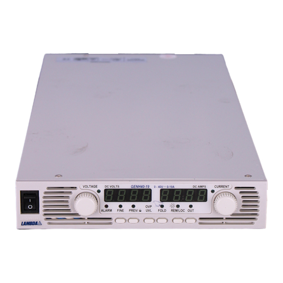
Page 34: Chapter 4 Front And Rear Panel Controls And Connectors
CHAPTER 4 FRONT AND REAR PANEL CONTROLS AND CONNECTORS 4.1 INTRODUCTION The Genesys Power Supply series has a full set of controls, indicators and connectors that al- low the user to easily setup and operate the unit. Before starting to operate the unit, please read the following Sections for explanation of the functions of the controls and connectors terminals. - Page 35 Table 4-1: Front Panel Controls and Indicators Number Control/Indicator Description Section 4 digit, 7 segment LED display. Normally displays the Output CURRENT display Current. When the PREV button is pressed, the display indi- cates the programmed setting of Output Current. CURRENT indicator Green LED, lights for Constant-Current mode operation High resolution rotary encoder for adjusting the Output Current.
-
Page 36: Rear Panelconnections And Controls
Number Control/Indicator Description Section Green LED, lights when PREV button is pressed PREV indicator Voltage and Current Fine/Coarse adjustment control. Op- FINE button erates as a toggle switch. In Fine mode, the VOLTAGE and CURRENT encoders operate with high resolution and in Coarse mode with lower resolution (approx. -
Page 37: Rear Panel Sw1 Setup Switch
Number Item Description Section RJ-45 type connector, used for daisy-chaining power supplies to Remote Out form a serial communication bus. connector Connector for remote analog interface. Includes Output Voltage and J1 Analog Current programming and monitoring signals, Shut-off control (elec- Remote trical signal), Enable/Disable control (dry-contact), Power Supply connector... -
Page 38: Resetting The Switch
Position Function DOWN (Factory default) Output Voltage Output Voltage Output Voltage SW1-1 programmed by remote programmed by remote analog programming analog voltage Front Panel Output Current Output Current Output Current CAUTION SW1-2 programmed by Front programmed by remote remote analog programming Panel analog voltage Terminals 12, 22 and 23 of J1 are connected internally to the... - Page 39 Fig.4-4: J1 connector terminals and functions Same ground as P/S negative sense (-S) IF_COM VMON IF_COM IPGM CV/CC VPGM ENA_IN LOC/ Isolated from ENA_OUT PS outputs, IMON IPGM_RTN same ground PS_OK VPGM_RTN as RS232/RS485 LOC/REM SIGNAL CAUTION To prevent ground loops and to maintain power supply isola- tion when programming from J1, use an ungrounded pro- gramming source.
- Page 40 Table 4-4: J1 connector terminals and functions Signal contact name Function Reference J1-1 ENA_IN Enable/Disable the power supply output by dry-contact Sec. 5.8 (short/open) with ENA_OUT. J1-2 IF_COM Isolated Interface Common. Return for the SO control, Sec.5.7, J1-3 PS_OK signal and for the optional IEEE interface. 5.10 J1-4i7 No Connection...
-
Page 41: Chapter 5 Local Operation
CHAPTER 5 LOCAL OPERATION 5.1 INTRODUCTION This Chapter describes the operating modes that are not involved in programming and monitoring the power supply via its serial communication port (RS232/RS485) or by remote analog signals. Ensure that the REM/LOC LED on the front panel is Off, indicating Local mode. If the REM/LOC LED is On, press the front panel REM/LOC button to change the operating mode to Local. -
Page 42: Constant Current Operation
-Enabled output, power supply in Constant Voltage mode: Press the PREV button and then rotate the CURRENT encoder knob. The CURRENT meter will show the pro- grammed Output Current for 5 seconds after the adjustment has been completed, and then will return to show the actual load current. -Enabled output, power supply in Constant Current mode: Rotate the CURRENT encoder knob to adjust the Output Current. -
Page 43: Under Voltage Limit
5.4 UNDER VOLTAGE LIMIT (UVL) The UVL prevents adjustment of the Output Voltage below a certain limit. The combination of UVL and OVP functions, allow the user to create a protection window for sensitive load circuitry. 5.4.1 Setting the UVL level Setting the UVL can be made when the power supply output is Enabled (On) or Disabled (Off). -
Page 44: Enable/Disable Control Via
applied to J1. This function is useful for connecting power supplies in a “Daisy-chain” (refer to Section 5.16). The SO control can also be used to reset the OVP and Fold Protection (refer to Section 5.3 and 5.5 for details). When the unit is shut-off by a J1 signal, the VOLTAGE display will show “SO”... -
Page 45: Ps Ok Signal
PS_OK SIGNAL The PS_OK signal indicates the fault condition of the power supply. PS_OK is a TTL signal out- put at J1-16, referenced to IF_COM at J1-2, 3 (Isolated Interface Common). When a fault condi- tion occurs, the PS_OK level is low, with a maximum sink current of 1mA; when no fault condition occurs, the PS_OK level is high with a maximum source current of 2mA. -
Page 46: Series Operation
9. Address setting 10. Baud rate 11. Locked/Unlocked Front Panel (LFP/UFP) (Items 8, 9, 10 are related to Remote Digital Control operation and are explained in Chapter 7) 12. Master/Slave setting. 5.14 SERIES OPERATION Power supplies of the SAME MODEL can be connected in series to obtain increased output volt- age. -
Page 47: Series Connection For Positive And Negative Output Voltage
1. Programming by external voltage: The analog programming circuits of this power sup- ply are referenced to the negative output potential. Therefore, the circuits used to control each series connected unit must be separated and floated from each other. 2.Using the SO function and PS_OK signal: The Shut-Off and PS_OK circuits are referenced to the isolated interface common, IF_COM (J1-2,3). -
Page 48: Parallel Operation
1. Programming by external voltage: The analog programming circuits of this power supply are referenced to the negative output po- tential. Therefore, the circuits used to control each series connected unit must be separated and floated from each other. 2. Using the SO function and PS_OK signal: The Shut-Off and PS_OK circuits are referenced to the isolated interface common, IF_COM (J1- 2,3). -
Page 49: Advanced Parallel Operation
up to 95% of its current rating because of the imbalance which may be caused by cabling and connection voltage drop. 3. Setting Over Voltage protection The Master unit OVP setting should be programmed to the desired OVP level. The OVP set- ting of the slave units should be programmed to a higher value than the Master OVP. - Page 50 a) When a unit is programmed to Slave mode it enters the Remote mode with Local Lockout. In this mode, the front panel controls are disabled to prevent accidental setting change (refer to Sec. 7.2.7 for details). Twisted pair Slave units parameters will...
-
Page 51: Daisy-Chain Shut-Off Connection
CAUTION Make sure that the connection between –V terminals is reliable to avoid disconnection during operation. Disconnection may cause damage to the power supply. NOTE With local sensing it is important to minimize the wire length and resistance. Also the positive and negative wire resistance should be close as possible to each other to achieve current balance be- tween power supplies 5.16 DAISY-CHAIN CONNECTION... -
Page 52: Unlocked Front Panel
5.17.1 Unlocked front panel In this mode, the front panel controls are Enabled to program and monitor the power supply pa- rameters. 5.17.2 Locked front panel In this mode the following front panel controls are Disabled: -VOLTAGE and CURRENT encoders. -FOLD button. -
Page 53: Chapter 6 Remote Analog Programming
CHAPTER 6 REMOTE ANALOG PROGRAMMING 6.1 INTRODUCTION The rear panel connector J1 allows the user to program the power supply Output Voltage and Current with an analog device. J1 also provides monitoring signals for Output Voltage and Out- put Current. The programming range and monitoring signals range can be selected between 0- 5V or 0-10V using the setup switch SW1. -
Page 54: Remote Voltage Programming Of Output Voltage And Current
CAUTION To maintain the power supply isolation and to prevent ground loops, use an isolated programming source when operating the power supply via remote analog programming at the J1 connector. Perform following procedure to set the power supply to Remote Voltage programming: 1. -
Page 55: Resistive Programming Of Output Voltage And Current
6.5 RESISITIVE PROGRAMMING OF OUTPUT VOLTAGE AND CURRENT LIMIT For resistive programming, internal current sources, for Output Voltage and/or Output Current control, supply 1mA current through external programming resistors connected between J1-9 & 22 and J1-10 & 23. The voltage across the programming resistors is used as a programming voltage for the power supply. -
Page 56: Remote Monitoring Of Output Voltage And Current
The J1 connector, located on the rear panel provides analog signals for monitoring the Output Voltage and Output Current. Selection of the voltage range between 0-5V or 0-10V is made by setup switch SW1-4. The monitoring signals represent 0 to 100% of the power supply Output Voltage and Output Current. -
Page 57: Chapter 7 Rs232 & Rs485 Remote Control
CHAPTER 7 RS232 & RS485 REMOTE CONTROL 7.1 INTRODUCTION This Chapter describes the operation of the Genesys 3300W power supplies via the serial communication port. Details of the initial set-up, operation via RS232 or RS485, the command set and the communication protocol are described in this Chapter. 7.2 CONFIGURATION 7.2.1 Default setting... -
Page 58: Rs232/458 Port At Local Mode
2. There are two Remote modes: 1. Remote: In this mode, return to local can be made by the front panel REM/LOC or via serial port command RMT 0. Set the unit into Remote mode via serial port RMT 1 command. 2. -
Page 59: Md Mode Option (Factory Installed)
7.4 MD MODE OPTION (Factory Installed) 7.4.1 MD Mode Description The GEN supply is capable of operating in a multi drop environment - more than 1 supply conducting serial communications on a single serial bus. A maximum of 31 GEN supplies can operate in this single bus. -
Page 60: Connecting Power Supplies To Rs232 Or Rs485 Bus
7.5 CONNECTING POWER SUPPLIES TO RS232 OR RS485 BUS 7.5.1 Single power supply 1. Select the desired interface RS232 or RS485 using rear panel setup switch SW1-6 (Section 4- -RS232: DOWN position -RS485: UP position 2. Connect rear panel IN connector to the controller RS232 or RS485 port using a suitable shielded cable. -
Page 61: Multi Power Supply Connection To Rs232 Or Rs485 Bus
7.5.2 Multi power supply connection to RS232 or RS485 bus Up to 31 units can be connected (daisy chained) to the RS232 or RS485 bus. The first unit con- nects to the controller via RS232 or RS485 and the other units are connected via the RS485 bus. 1. -
Page 62: Acknowledge
STAT?$7B 7.6.6 Acknowledge The power supply acknowledges received commands by returning an “OK” message. If an error is detected the power supply will return an error message. The rules of checksum also apply to the acknowledge. 7.6.7 Error message If an error is detected in command or query, the power supply will respond with an error mes- sage. -
Page 63: Initialization Control Commands
3. Output control 4. Status control 7.8.3 Initialization Control Commands Command Description ADR is followed by address, which can be 0 to 30 and is used to access the ADR n power supply. Clear status. Sets FEVE and SEVE registers to zero (refer to Section 7-11). Reset command. - Page 64 Note 1) lowing examples for PC n format: PC n format: PC 10, PC 10.0, PC 010.00, etc… Reads the Output Current setting. Returns the string “n” where “n” is the ex- act string sent in the PC n command. When in Local mode, returns the PREVIEW (front panel) settings in a 5 digit string.
-
Page 65: Global Output Commands
AST? Returns the string auto-restart mode status. Saves present settings. The settings are the same as power-down last set- ting. These settings are erased when the supply power is switched Off and the new “last settings” are saved. Recalls last settings. Settings are from the last power-down or from the last “SAV”... -
Page 66: Single Byte Commands
7.10 SINGLE BYTE COMMANDS 7.10.1 General Single byte commands are commands in which all the necessary data for the supply to act upon is contained in a single byte. Single byte commands will be executed immediately by the supply. If the command requires data to be sent to the HOST PC or IEEE Board (see sections 7.10.4 and 7.10.3.1) that response will be transmitted immediately with no delay due to any software overhead. -
Page 67: Global Commands With Response
7.10.3 Global commands with response 7.10.3.1 Disconnect from communications Command the supply to end all data transmissions to the HOST PC/IEEE Board and cease its role as the active addressed supply. The HOST PC/IEEE Board will be re- quired to re-send the ‘ADR nn’ command to reestablish communications with the sup- ply. -
Page 68: Addressed Commands Without Response
7.10.4.4 Test if MD Mode is Installed Send AA Hex followed by the address of the supply in binary. If not installed, the sup- ply will return a ‘1’. If installed, the supply will return a ‘0’. 7.10.5 Addressed commands without response 7.10.5.1 Acknowledge SRQ Send (0xE0 + Address) (1 byte binary - send 2 times sequentially). - Page 69 returned. 110x xxxx Retransmit last response from a Retransmit last Last message command. x xxxx is the address of message the supply in binary. 111x xxxx Acknowledge SRQ. If retransmis- Acknowledge None sion of SRQ is enabled, it will re- main enabled for the next SRQ.
-
Page 70: Status Control Commands
10.0 7.60 12.5 15.0 12.5 11.9 24.0 19.0 36.0 28.5 44.0 38.0 66.0 57.0 88.0 76.0 110.0 95.0 165.0 330.0 660.0 7.10.6 Status Control Commands Refer to Section 7-8 for definition of the registers. Command Description STT? Reads the complete power supply status. Returns ASCII characters representing the following data, separated by commas: MV<actual (measured) voltage>... -
Page 71: Status Registers
Command Error (”Cnn”) One response for every command or query received. Execution Error (”Enn”) Response messages Query Response (”message”) Command Response (”OK”) Status Registers Serial Condition Enable Event Constant Voltage Constant Current “Inn” and CR No Fault NFLT NFLT Fault Auto Start Messages Fold Enabled... -
Page 72: Service Request Enabled And Event Registers
7.11.2 Conditional Registers (continued) Table 7-8: Fault Condition Register Fault name Fault symbol Bit Set condition Bit Reset condition 0 (LSB) Spare bit SPARE Fixed to zero Fixed to zero AC Fail AC fail has occurred. The AC input returns to normal. Over OTP shutdown has The power supply cools down. - Page 73 The SRQ message is: “Inn” terminated by CR, where the nn is the power supply address. The SRQ will be generated either in Local or Remote mode. Refer to Tables 7-10 to 7-13 for details of the Enable and Event registers. 1.
- Page 74 3. Status Enable Register The Status Enable Register is set by the user to Enable SRQs for changes in power supply status. Table 7-12: Status Enable Register Status sym- Status name Bit Set condition Bit reset condition 0 (LSB) User command: “SENA Constant Voltage nn”...
-
Page 75: Serial Communication Test Set-Up
7.12 SERIAL COMMUNICATION TEST SET-UP Use the following instructions as basic set-up to test the serial communication operation. 1.Equipment: PC with Windows Hyper Terminal, software installed, Genesys Power supply, RS232 cable. 2. PC set-up: 2.1 Open Hyper Terminal……………………. New Connection. 2.2 Enter a name 2.3 Connect to…………………………………... -
Page 76: Chapter 8 Isolated Analog Progamming Option
CHAPTER 8 ISOLATED ANALOG PROGRAMMING OPTION 8.1 INTRODUCTION Isolated Analog Programming is an internal Option Card for analog programming of the Gene- power supply series. The option is factory installed and cannot be obtained with a GPIB (IEEE-488) Interface. Output Voltage and Output Current can be programmed and readback through optically isolated signals which are isolated from all other ground references in the power supply. -
Page 77: Isolated Programming & Monitoring Connector
8.3 ISOLATED PROGRAMMING & MONITORING CONNECTOR Refer to Table 8-1 for detailed description of the rear panel Isolated Programming & Monitoring connector. To provide the lowest noise performance, it is recommended to use shielded-twisted pair wiring. Refer to Fig.8-1 for description of the Isolated Analog Programming & Monitoring connector. Isolated programming plug P/N: MC1.5/8-ST-3.81, Phoenix. -
Page 78: Setup And Operating Instructions
8.4 SETUP AND OPERATING INSTRUCTIONS CAUTION To prevent damage to the unit, do not program the output voltage and current to higher than the power supply rating. 8.4.1 Setting up the power supply for 0-5V/0-10V Isolated Programming and Monitoring Perform the following procedure to configure the power supply: 1. -
Page 79: Chapter 9 Maintenance
CHAPTER 9 MAINTENANCE 9.1 INTRODUCTION This Chapter provides information about maintenance, calibration and troubleshooting. 9.2 UNITS UNDER WARRANTY Units requiring repair during the warranty period should be returned to a Lambda authorized ser- vice facility. Refer to the addresses listing on the back cover of this User’s Manual. Unauthorized repairs performed by other than the authorized service facilities may void the warranty. -
Page 80: Fuse Rating
SYMPTOM CHECK ACTION Output Voltage will not Is the unit in constant Check Output Current 5.2.1 adjust. Front panel CC LED current mode? setting and load current. 5.2.2 is On. Output Voltage will not Check if output voltage is Set OVP or UVL so they will adjust Front panel CV Led is adjusted above OVP not limit the output. - Page 81 Table 9-2: Internal fuses Fuse designation 750W model F301 20A 250VAC, FAST F302, F304 2A 400VDC, NORMAL F31, F32 NOT USED 83-507-5002 Rev. A...
Need help?
Do you have a question about the Genesys GENH 750W and is the answer not in the manual?
Questions and answers