
Subscribe to Our Youtube Channel
Related Manuals for Lambda 303 Series


Summary of Contents for Lambda 303 Series
-
Page 1: Power Supply
OPERATOR MANUAL FOR 303 Series High Voltage POWER SUPPLY Document: 83-489-009 Rev A LAMBDA AMERICAS 405 Essex Road, Neptune, NJ 07753 Tel: (732) 922-9300 Fax: (732) 922-9334 Web: www.us.tdk-lambda.com/hp 83-489-009 Rev A... -
Page 3: Table Of Contents
OUT-OF-BOX-INSPECTION................3-9 VISUAL INSPECTION....................3-9 ELECTRICAL INSPECTION...................3-9 3.2.1 TEST 1 ..........................3-9 3.2.2 TEST 2 ..........................3-9 CONTACTING LAMBDA AMERICAS CUSTOMER SERVICE ......3-10 RETURNING DEFECTIVE UNITS ...............3-10 INSTALLATION....................4-11 19-INCH RACK MOUNTING ................4-11 VENTILATION REQUIREMENTS ................4-12 WATER COOLING REQUIREMENTS ..............4-12 ORIENTATION.....................4-12 AC POWER CONNECTION.................4-13 CONNECTING THE HIGH VOLTAGE OUTPUT ..........4-14... - Page 4 CONTROLS, INDICATORS, CONNECTORS ..........5-1 FRONT PANEL LAYOUT (L Model) ...............5-1 Power Supply Status LEDs (Ref 1).................5-2 5.2.1 Operating Status LEDs....................5-2 5.2.1.1 READY (Normally ON) ....................5-2 5.2.1.2 LINE (Normally ON)......................5-2 5.2.1.3 INHIBIT (Normally ON) ....................5-2 5.2.1.4 END OF CHARGE (Normally OFF) ................. 5-2 5.2.1.5 AUTO DWELL (Normally OFF) ..................
- Page 5 TABLE OF CONTENTS OPERATING INSTRUCTIONS..............6-15 LOCAL OPERATION (203/303L only) ..............6-15 REMOTE OPERATION (All models) ..............6-16 6.2.1 Remote Control Signals ....................6-17 6.2.2 Remote Operation with AUTODWELL ................6-17 6.2.3 Remote Operation with INHIBIT..................6-19 Parallel Operation....................6-20 6.3.1 Parallel system comprising 203/303L supplies ............. 6-20 6.3.2 Parallel system comprising both 203/303L and 203/303S supplies ......
-
Page 7: General Information
GENERAL INFORMATION INTRODUCTION Lambda Americas ALE series 203 and 303 are state of the art switch mode high voltage power supplies, designed primarily for capacitor charging applications such as laser sys- tems, modulators, and pulse forming networks. They can also be used in many continu- ous DC applications including beam power for magnetrons, gyrotrons, klystrons and electron beam loads. -
Page 8: Capacitor Charging Technology
GENERAL INFORMATION • Powering lasers: Excimer, flashlamp pumped dye, Yag, CO , etc. • Line type modulators for RF generation and pulse discharge applications in re- search. • Continuous power for RF tubes – magnetron, gyrotron, TWT, klystron etc. • Electron beam applications. -
Page 9: Safety Precautions
SCOPE OF THIS MANUAL This manual is used for installing and operating the 203 and 303 Series Power Supply. Suggestions and requirements for connecting AC power, load cables and signal cables are given. Various operating modes and programming modes are described. -
Page 10: Table 1-1 Model Description Format
Table 1-1 shows a partial listing of the model description format for the 203/303 Power Supply family. For additional options, the customer may contact the Sales Department at Lambda Americas. Special options are typically shown as a four-digit suffix to the model number. -
Page 11: Specifications
SPECIFICATIONS SPECIFICATIONS Output Power MAXIMUM OUTPUT POWER RATING AC INPUT MODE VOLTAGE MODEL 203 MODEL 303 Cap Charging 20kJ/sec av, 25kJ/sec pk 30kJ/sec av, 37.5kJ/sec pk 432-528 VAC, 50-60 Hz, 3φ Continuous DC 30kW 50kW Cap Charging 20kJ/sec av, 25kJ/sec pk 25kJ/sec av, 32.5kJ/sec pk 360-440 VAC, 50-60 Hz, 3φ... -
Page 12: Input Power
SPECIFICATIONS Input Power: MAXIMUM INPUT CURRENT AC INPUT VOLTAGE MODEL 203 MODEL 303 40A/Phase (Cap charging) 60A/Phase (Cap charging) 432-528 VAC, 50-60 Hz, 3φ 60A/Phase (Continuous DC) 98A/Phase (Continuous DC) 47A/Phase (Cap charging) 71A/Phase (Cap charging) 360-440 VAC, 50-60 Hz, 3φ 71A/Phase (Continuous DC) 94A/Phase (Continuous DC) 94A/Phase (Cap charging) -
Page 13: Water Fittings
SPECIFICATIONS 2.16 Water Fittings 1/4 inch NPT male threaded pipes 2.17 Weight 190 lbs. (86.4 kg) approx. 2.18 Shock and Vibration Unboxed 0.5 g. Factory packing 2.0 g 2.19 Shipping Gross weight with packing material: 240 lbs. (109 kg) approx. Size: 27"W X 21"... - Page 14 SPECIFICATIONS NOTES:...
-
Page 15: Out-Of-Box-Inspection
OUT-OF-BOX-INSPECTION OUT-OF-BOX-INSPECTION VISUAL INSPECTION Prior to shipment, this instrument was inspected and found to be free of mechanical and electrical defects. As soon as the unit is unpacked, inspect for any damage that may have occurred in transit. Verify the following: A. -
Page 16: Contacting Lambda Americas Customer Service
The supply and the FC-72 filled HV assembly should not be opened unless advised by Lambda Americas personnel. The FC-72 filled HV tank has been cleaned and the her- metically sealed at the factory, opening the supply or the assembly will void the factory warranty, and may compromise performance. -
Page 17: Installation
INSTALLATION 4-11 INSTALLATION 19-INCH RACK MOUNTING This power supply is intended for mounting in a conventional 19-inch rack. It’s 12.25 inch height makes it a “7U” size instrument. The rack should enclose the sides, top and back to protect the operator from electrical shock and protect the supply from environ- mental contamination. -
Page 18: Ventilation Requirements
INSTALLATION 4-12 19” (482mm) 19” (482mm) 17” (432mm) 17” (432mm) 4.52” 4.52” 4.21” 4.21” 4.21” (115mm) (115mm) (107mm) (107mm) (107mm) 11.56” 11.56” (294mm) (294mm) 6.00” 6.00” (152mm) (152mm) 3.5” 3.5” (89mm) (89mm) Figure 4-2 203/303 Rear View VENTILATION REQUIREMENTS Ensure there is at least 5 inches (12.5 cm) of clearance at the rear of the unit for air- flow, cables and water lines. -
Page 19: Ac Power Connection
550VAC. If this voltage is exceeded, catastrophic damage will result, that is not covered by Lambda Americas standard warranty. The customer’s AC power line connects to the 203/303 via a UL/CSA approved 5 posi- tion terminal block on the rear panel of the unit (see Figure 4-3). Only use a power cable with the correct voltage and current rating (see Table 4-1). -
Page 20: Connecting The High Voltage Output
Always use the HV connector and cable provided with the power supply or an equivalent substitute provided by Lambda Americas. Fully insert the connector end of the HV cable and tighten the locking nut only "hand tight". When operating above 20kV and 200Hz rep rate a silicone grease (such as Dow Corn- ing DC-4) must be applied to the HV cable before insertion into the HV connector. -
Page 21: L Oad C Ircuit C Onnection
Generally, a resistor in series with the HV output can be added to limit this current to an acceptable level. Refer to Application Note 517 (available from the factory or at www.lambda-emi.com) for more information. LOAD CIRCUIT... - Page 22 INSTALLATION 4-16 NOTES:...
-
Page 23: Ront P Anel C Ontrols And I Ndicators
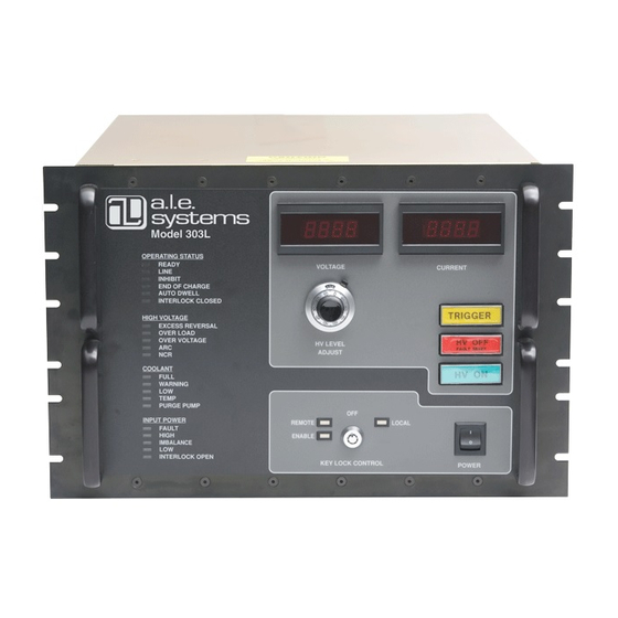
CONTROLS, INDICATORS, CONNECTORS CONTROLS, INDICATORS, CONNECTORS FRONT PANEL LAYOUT (L Model) The 203/303L series power supply is equipped with a fully instrumented front panel fea- turing output voltage control, voltage and current metering, and comprehensive status LEDs, along with local/remote mode keyswitch, and power on switch. The 203/303L can be operated locally from the front panel or remotely via the control connector located on the rear panel (see Section 6.2). -
Page 24: Controls, Indicators, Connectors
CONTROLS, INDICATORS, CONNECTORS DESCRIPTION NOTE SECTION Status LEDs Indicates the status of the power supply Local Voltage Set 10 turn pot for setting output voltage in local mode Voltage Display Digital display of output or set voltage Current Display Digital display of average output current TRIGGER Push But- Indicates presence of Inhibit signal, and controls supply in single shot trigger mode... -
Page 25: Auto Dwell (Normally Off)
Refer to Application Note 517 (available from the factory or at www.us.tdk- lambda.com/hp) for more information. 5.2.2.2 OVERLOAD (Normally OFF) The OVERLOAD circuit indicates if a short circuit or an extremely large capacitor is in- advertently connected to the power supply. -
Page 26: Overvoltage (Normally Off)
5.2.3 COOLANT status LEDs In the event of any coolant faults the user should verify installation orientation is in ac- cordance with section 3.4 prior to contacting Lambda Americas. 5.2.3.1 FULL (Normally ON) When illuminated, this indicator signals that the high voltage tank in filled to the correct level with coolant. -
Page 27: Temp (Normally Off)
CONTROLS, INDICATORS, CONNECTORS 5.2.3.4 TEMP (Normally OFF) The TEMP LED Illuminates if the HV tank temperature is outside of its operating limits. The fixed operating limits have minimum low temperature and a maximum high tem- perature. When illuminated, the TEMP indicator will turn OFF the high voltage output. When the internal temperature returns to a normal level, the output may be switched back on by depressing the HV ON push-button. -
Page 28: Low (Normally Off)
CONTROLS, INDICATORS, CONNECTORS 5.2.4.4 LOW (Normally OFF) The LOW AC line LED will illuminate if the AC input voltage drops below approximately 85% of the nominal nameplate level. The power supply will continue to deliver output current unless voltage dip is too great (either low voltage or for a long time). The power supply will shut down the output until the AC line is restored. -
Page 29: Local Voltage Control (Ref 2)
CONTROLS, INDICATORS, CONNECTORS LOCAL VOLTAGE CONTROL (Ref 2) The local voltage control potentiometer is a precision 10 turn dial indicator that adjusts the output voltage between zero and 100% of rated voltage. The output voltage can be set at the desired level by turning the dial to the required percentage before depressing the HV ON push button. -
Page 30: Off Position
CONTROLS, INDICATORS, CONNECTORS 5.7.1 OFF Position With the KEY LOCK in the OFF position, the POWER switch may be turned but HV can- not be turned on. The unit may be locked in the OFF position and the key removed to protect equipment and personnel. -
Page 31: Hv On (Ref 8)
CONTROLS, INDICATORS, CONNECTORS HV ON (Ref 8) DO NOT DEPRESS THE HV ON PUSH-BUTTON UNLESS A SUITABLE CAPACITIVE LOAD IS CONNECTED TO THE POWER SUPPLY'S OUTPUT CABLE, AND THE LOAD IS CORRECTLY GROUNDED The HV ON push button turns ON the high voltage output when depressed only after all interlocks are closed, self checks are completed and the unit is switched to the LOCAL mode. -
Page 32: Rear Panel Layout (L Models)
CONTROLS, INDICATORS, CONNECTORS 5-10 A.L.E. SYSTEMS A.L.E. SYSTEMS MODEL 203 / 303 L MODEL 203 / 303 L Figure 5-2 203/303S Front Panel Controls and Indicators DESCRIPTION NOTE SECTION Status LEDs Indicates the status of the power supply Power switch Turns on/off power to auxiliary circuits 5.10 Table 5-3 Front Panel Controls and Indicators (S Model) -
Page 33: Ear P Anel C Onnections
CONTROLS, INDICATORS, CONNECTORS 5-11 Figure 5-3 203/303L Rear Panel Connections DESCRIPTION NOTE SECTION Inhibit BNC BNC socket for external inhibit signal 5.12.1 Coolant Water Inlet ¼ NPT male threaded coolant inlet pipe 5.12.2 HV Output Connector HV output connector 5.12.3 Coolant Water Out ¼... -
Page 34: Inhibit Bnc (Ref 1)
CONTROLS, INDICATORS, CONNECTORS 5-12 The function of each item in Table 5-4 is described in the following sections. 5.12.1 INHIBIT BNC (Ref 1) The inhibit BNC input is a standard BNC socket that allows an external connection to a pulse generator or control system and gives the user control of the power supply output current. -
Page 35: Safety Ground
CONTROLS, INDICATORS, CONNECTORS 5-13 5.12.10 Safety ground 10-32 safety ground screw installed in chassis. Should be used for additional safety ground cable between supply and load circuit. 5.12.11 AC input terminal Main AC input power terminal block see section 4.5 for further details. 5.13 REAR PANEL LAYOUT (S Models) The 303S rear panel is almost identical to the 303L except these is no SLAVE or INHIBIT BNC connector. - Page 36 CONTROLS, INDICATORS, CONNECTORS 5-14 NOTES:...
-
Page 37: Operating Instructions
NOTE: The 203/303 series power supplies are not designed to operate into an open cir- cuit load. Operating the supply with no external load capacitor could result in damage to the high voltage output section and would void the warranty. -
Page 38: Remote Operation (All Models)
OPERATING INSTRUCTIONS 6-16 To turn OFF the power supply depress the OFF button or use the inhibit line. Opening the interlock terminals will also cause the power supply to turn off. In this case the unit can only be turned back on after the interlock has been closed and the ON button de- pressed followed by the OFF button to RESET the fault. -
Page 39: Remote Control Signals
6.2.2 Remote Operation with AUTODWELL The simplest remote control for the 203/303 series power supplies requireds only an ex- ternal HV ON/OFF signal (Pin 10), and a Vprogram signal (Pin11), and ground (Pin 21/23). The Vprogram signal should be set to the appropriate analog level that corre- sponds to the desired output voltage. - Page 40 OPERATING INSTRUCTIONS 6-18 INTERLOCK INTERLOCK OPEN OPEN READY READY READY INPUT POWER FAULT INPUT POWER FAULT INHIBIT INHIBIT AUTO DWELL AUTO DWELL END OF CHARGE END OF CHARGE OVERLOAD OVERLOAD EXCESS REV ERSAL EXCESS REV ERSAL COOLANT WARNING COOLANT WARNING COOLANT FAILURE (LOW COOLANT OR TEMP FAULT) COOLANT FAILURE (LOW COOLANT OR TEMP FAULT) OVER VOLTAGE...
-
Page 41: Remote Operation With Inhibit
OPERATING INSTRUCTIONS 6-19 that shuts off the output current for a short period (1ms default). Note: the AUTODWELL period is programmable between 500µs and 5ms via remote Pin 9. The AUTODWELL circuit will only detect load discharge when the output voltage falls from between 20% and 100% of rated voltage to zero. -
Page 42: Parallel Operation
Figure 6-3 Remote Interface waveforms for 303 operated with INHIBIT Parallel Operation The 203/303 series capacitor charging power supplies are constant current sources, and can be connected in parallel for applications requiring increased power. To operate more than one unit in parallel all that is required is a parallel control cable, and to con- nect the HV output cables together at the load. -
Page 43: Parallel System Comprising Both 203/303L And 203/303S Supplies
OPERATING INSTRUCTIONS 6-21 ‘daisy chained’ to the REMOTE connector on each of the SLAVE supplies. Note: The master 203/303L supply in a parallel system only displays the status, voltage, and cur- rent output for that unit, not for the entire system. The slave supplies will also display the voltage and current only for that specific unit. - Page 44 OPERATING INSTRUCTIONS 6-22 From Optional Control System From Optional Control System From Optional Control System From Optional Control System From Control System From Control System L Model Parallel System L Model Parallel System L & S Model Parallel System L & S Model Parallel System S Model Parallel System S Model Parallel System Figure 6-4 Parallel Operation Connections...
-
Page 45: Application Notes
The latest ver- sions of these application notes are available for download at the Lambda web site (www.us.tdk-lambda.com/hp/high_volt.htm). - Page 47 3700 3700 3700 3700 3700 3700...
- Page 53 An Invensys company...
Need help?
Do you have a question about the 303 Series and is the answer not in the manual?
Questions and answers