Lambda ZUP6-33 User Manual

Lambda ZUP6-33 User Manual

Programmable dc power supplies constant voltage/constant current built-in rs232 & rs485 interface with gpib option.
Table of Contents

Advertisement

ZERO-UP
Programmable DC Power Supplies
Constant Voltage/Constant Current
Built-in RS232 & RS485 Interface
with GPIB option.
C
US
LISTED
..
..
geprufte
TESTING EQUIPMENT
TUV Rheinland
Sicherheit
65SA
USER'S MANUAL
DENSEI-LAMBDA
200W/400W/800W

Advertisement

Table of Contents
loading
Need help?

Need help?

Do you have a question about the ZUP6-33 and is the answer not in the manual?

Questions and answers

Subscribe to Our Youtube Channel

Summary of Contents for Lambda ZUP6-33

  • Page 1 DENSEI-LAMBDA ZERO-UP 200W/400W/800W Programmable DC Power Supplies Constant Voltage/Constant Current Built-in RS232 & RS485 Interface with GPIB option. LISTED geprufte TESTING EQUIPMENT TUV Rheinland Sicherheit 65SA USER'S MANUAL...
  • Page 2: Declaration Of Conformity

    EMC directive 89/336/EEC for Electrical Equipment used in Measurement Control and Laboratory environments, and carries the CE mark accordingly. Our importer to the EU is Coutant Lambda Limited, located at Kingsley Avenue, Ilfracombe, Devon EX34 8ES, UK. Further, all products covered by this declaration are manufactured by processes which ensure continued compliance of the products with the requirements of the Low voltage and the EMC directives.
  • Page 3: Introduction

    TABLE OF CONTENTS: ZUP SERIES WARRANTY ..................pg. 1 SAFETY INSTRUCTIONS ..............pg. 2 CHAPTER 1. General Information ............pg. 5 1.1 User manual content 1.2 Introduction 1.2.1 General description 1.2.2 Configurations 1.2.3 Control via the serial communication port 1.2.4 Output connections 1.2.5 Analog voltage programming 1.2.6 Parallel operation 1.2.7 Cooling and mechanical construction ........
  • Page 4: Table Of Contents

    TABLE OF CONTENTS: ZUP SERIES 3.10 Outline drawings: ZUP 200W & 400W series......... pg.19 3.11 Outline drawing: ZUP 800W series..........pg.20 3.12 Outline drawing: front panel connector option ....... pg.21 CHAPTER 4. Operating Instructions..........pg.22 4.1 Introduction 4.2 Controls and Indicators
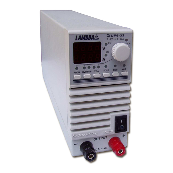
 4.2.1 Front Panel Table 4-1: Front panel controls and indicators ........
  • Page 5: Status Control

    TABLE OF CONTENTS: ZUP SERIES 5.3 Remote programming via RS232............. pg.39 5.3.1 Introduction 5.3.2 Rear panel connectors pinout 5.3.3 RS232 cable ................pg.40 5.3.4 Linking power supplies 5.4 Remote programming via RS485 ............. pg.41 5.4.1 Introduction 5.4.2 RS485 cable 5.4.3 Linking power supplies 5.5 ZUP series command set description pg.42 5.5.1 ID control commands...............
  • Page 6: Limitation Of Warranty

    This Nemic-Lambda product is warranted against defects in materials and workmanship for a period of three years from date of shipment .During the warranty period, Nemic-Lambda will, at it’s option, either repair or replace products which prove to be defective.
  • Page 7: Safety Instructions

    PART SUBSTITUTIONS & MODIFICATIONS Part substitutions and modifications are allowed by authorized Nemic-Lambda service personnel only. For repairs or modifications, the instrument must be returned to a Nemic-Lambda service facility. ENVIRONMENTAL CONDITIONS The ZUP series safety approval applies to the following operating conditions:...
  • Page 8: Safety Symbols

    SAFETY INSTRUCTIONS SAFETY SYMBOLS Instruction manual symbol. The instrument will be marked with this symbol when it is necessary for the user to refer to the instruction manual. Indicates hazardous voltage. Indicates ground terminal. The WARNING sign denotes a hazard. An attention to a procedure is called. WARNING Not following procedure correctly could result in personal injury.
  • Page 9 SAFETY INSTRUCTIONS OUTPUT TERMINALS COVER Models up to 60V output voltage WARNING Hazardous voltages may exist at the output terminals. Attach the terminals cover, supplied with the unit, to the chassis after connecting the load wires as described below. After connection of the load wires ( refer to par. 3-7 ), attach the plastic cover to the rear panel of the power supply, using two self tapping screws supplied with the unit.
  • Page 10: Chapter 1 General Information

    CHAPTER 1 GENERAL INFORMATION 1.1 USER’S MANUAL CONTENT This user’s manual contains the operating instructions, installation instructions and specifications of the ZUP series. For information related to operation with GPIB control, refer to Nemic-Lambda GP485 user’s manual. 1.2 INTRODUCTION 1.2.1 General description The ZUP series are wide range output switching power supplies with laboratory performance.
  • Page 11: Linking Power Supplies

    1.2.7 Cooling and mechanical construction The Zup series is fan cooled. Upon installation take care to allow free air flow into the power supply via the front panel and out of the power supply via the rear panel. The ZUP series is contained in a compact, lightweight package which allows for easy installation and space saving in the application equipment.
  • Page 12 CHAPTER 2 SPECIFICATIONS 2.1 SPECIFICATIONS: 200W/400W Series...
  • Page 13 2.1 SPECIFICATIONS: 200W/400W Series continued...
  • Page 14 2.1 SPECIFICATIONS: 800W Series...
  • Page 15 2.1 SPECIFICATIONS: 800W Series continued...
  • Page 16: Supplemental Characteristics

    Performance of the power supply under IEC 1000 test conditions. 4. EMI DATA: Typical EMI (conducted and radiated) performance of the power supply. The supplemental characteristics data are held in each Nemic-Lambda sales and service facility. For further details please contact the Nemic-Lambda office nearest you.
  • Page 17: Chapter 3 Installation

    Upon unpacking of the power supply, inspect for any damage which may have occurred in transit. Keep all packing materials until inspection has been completed. If any damage is detected, file a claim with the carrier immediately and notify the Nemic-Lambda sales or service facility nearest you. 3.2.1 Mechanical inspection The mechanical inspection should confirm that there is no exterior damage to the power supply such as broken knobs or connectors and that the front panel and meter face are not scratched or cracked.
  • Page 18: Connecting The Load

    This power supply is equipped with a three conductor power cable. The third conductor is the ground conductor. When the cable is plugged-in to an appropriate receptacle, the power supply is grounded. Under no circumstances should this power supply be operated without an adequate ground connection.
  • Page 19: Wire Termination

    Maximum length in meters - to limit voltage drop to 0.5V or less < 150A 8.21 12.2 5.09 19.6 3.39 29.5 14.7 1.95 51.3 25.6 12.8 1.24 80.6 40.3 20.2 0.795 125.8 62.9 31.4 12.6 0.565 177.0 88.5 44.2 17.7 Table 3-2: Maximum wire length for 0.5V drop on lead (in meters) For current not shown in tables 3-1 and 3-2 use formula: Maximum length=500/(current*resistivity) Where current is expressed in ampers and resistivity in ohms/km or ohms/1000ft.
  • Page 20: Single Load Connection, Remote Sensing

    3.7.4 Single load connection, Remote Sensing Remote Sensing is used in cases where, in Constant Voltage mode the load regulation is important at the load terminals. Use twisted or shielded wires to minimize noise pick-up. If shielded wires are used, the shield should be connected to the ground at one point, either the power supply chassis or the load ground.
  • Page 21: Grounding Outputs

    3.7.6 Multiple load connections with distribution terminals If remotely located output distribution terminals are used, the power supply output terminals should be connected to the distribution terminals by a pair of twisted or shielded wires. Each load should be separately connected to the remote distribution terminals. If Remote Sensing is required, the sensing wires should be connected to the distribution terminals or at the most critical load.
  • Page 22: Pin Description

    3.8.2 Pin Description Name Description Par. Resistive Constant Voltage programming 4.4.10 RCVP Resistive Constant Current programming 4.4.10 RCCP Reference voltage for Constant Current control. (connected to 4.4.10, 11, 12 VRFI VCCP pin except external voltage or resistive programming). Input of the Constant Current control circuit. 4.4.10, 11, 12 VCCP Reference voltage for Constant Voltage control.
  • Page 23: Repackaging For Shipment

    If the original package is not available, contact the Nemic- Lambda Sales or service facility near you for details on obtaining suitable packaging and shipping information. Please attach a tag to the power supply describing the problem and specifying the owner,...
  • Page 26: Outline Drawings

    3.12 OUTLINE DRAWINGS Front Panel Output Jacks Option: available for ZUP200W , ZUP400W and ZUP800W series for 6V to 60V models. ZUP200/L and ZUP400/ L ZUP200/L and ZUP400/ L ZUP800/L Up to 20A output current via front panel jacks. CAUTION: ZUP800 front panel output is protected against overcurrent by 25A 125V Fast acting fuse. For continued protection against risk of fire, replace only with same type and rating of fuse.
  • Page 27: Introduction

    CHAPTER 4 OPERATING INSTRUCTIONS INTRODUCTION This chapter describes the operating modes, controls and indicators of the ZUP power supply series. Details of local operation via the front panel and various modes of operation are described in this chapter, including remote analog control via the rear panel. For computer control via the Serial port (RS232 or RS485), refer to chapter 5.
  • Page 28: Table 4-1: Front Panel Controls And Indicators

    Table 4-1: Front panel controls and indicators Control/Indicator Description Par. Actual output current display at normal operation. While adjusting the output current, the set value will be shown. AMPS Display The display will automatically return to show the actual current approx. 3sec from completion of adjustment. Actual output voltage display at normal operation.
  • Page 29: Rear Panel

    Table 4-1 contd.: Front panel controls and indicators Control/Indicator Description Par. Turns AC power On and Off. AC ON/OFF V/A Pushbutton Selects the voltage or current adjust mode. fast or slow 4.4.2 adjustment speed can be selected by pressing the 4.4.3 pushbutton consecutively.
  • Page 30: Prior To Operation

    4.2.3 Rear Panel Connections description Connection Description Par. IEC type appliance inlet. AC Inlet Remote In EIA/TIA-568A type connector, used for connecting power 5.3.4 supply to RS232 or RS485 port of computer for remote control purposes. When using several power supply units in a power system, the first unit Remote-in is connected to the computer and the remaining units are chained, Remote-In to Remote-Out.
  • Page 31: Constant Current Check

    4.3.4 Constant Current check Turn off the power supply. Connect an electronic load with suitable voltage and current rating to the output terminals, as explained in paragraph 3.7.3. Turn-on the power supply. Vary the load current and check that the unit regulates the output voltage while the load current is smaller than the power supply current rating.
  • Page 32: Local Operation

    LOCAL OPERATION 4.4.1 Introduction This paragraph describes the operating modes not involved in programming the power supply via it’s serial communication port. Operation utilizing the front and rear panel are described in this paragraph. For information regarding serial port usage, please refer to chapter 5. The REM LED on the front panel indicates whether the power supply is in Local or Remote mode.
  • Page 33: Automatic Crossover

    4.4.4 Automatic Crossover If the power supply operates in Constant voltage mode while the load current is increased to greater than the current limit setting, the power supply will automatically switch to Constant current mode. If the load is decreased to less than the current limit setting, the power supply will automatically switch back to Constant voltage mode.
  • Page 34: Foldback Protection

    4.4.7 Foldback Protection 1. Foldback protection will shut down the power supply output if the load current exceeds the current limit setting level. This protection is useful when the load circuitry is sensitive to over current condition. 2. To arm the Foldback protection, the FOLD pushbutton should be pressed so the FOLD LED illuminates.
  • Page 35: Fold

    4.4.9 Last Setting Memory The ZUP series is equipped with Last Setting Memory which stores all power supply parameters at each ac turn-off sequence of the power supply. The OUT parameter storage is determined prior to the ac turn-off to allow two modes of re-start of the power supply. STORED PARAMETERS 1.
  • Page 36 4. OUTPUT VOLTAGE PROGRAMMING BY EXTERNAL RESISTOR Fig 4-5 shows a typical set-up for programming the output voltage. A variable programming resistor, 0~4Kohm produces a proportional output voltage from zero to full scale. In order to set the low limit, a series resistor can be connected to the programming resistor.
  • Page 37: Output Voltage Programming By External Voltage

    4.4.11 Output Voltage Programming by external voltage Fig. 4-7 shows the set-up for external voltage programming of the output voltage. A voltage source variable from 0 to 4V, programs the output voltage proportionally from zero to full scale. The static load current on the programming source is less than 2uA.
  • Page 38: Auto Parallel Operation

    4.4.13 Auto Parallel Operation 1.Up to five units of the same rating can be connected in an auto-parallel combination to provide up to five times the output current capability. One of the power supplies operates as a master and the remaining units as slaves.
  • Page 39 - LS MASTER On/Off POWER Output Good SUPPLY VCVP VRFV VCCP VRFI RCCP RCVP LOAD - LS SLAVE On/Off POWER Output Good SUPPLY VCVP VRFV VCCP VRFI RCCP RCVP Fig. 4-10: Local sensing with distribution terminals. (ZUP rear panel view) - LS MASTER On/Off...
  • Page 40: Series Operation

    4.4.14 Series Operation 1. GENERAL: Two power supplies of the same rating can be connected in series to increase the output voltage or to provide bipolar output voltage. CAUTION When two power supplies are connected in series, they should be programmed to the same output voltage to prevent damage to the lower voltage supply at short circuit condition.
  • Page 41 3. Series connection for bipolar output voltage: 3.1 General: At this operation mode, two units are configured as a bipolar voltage/current source. Set the current limits of each power supply to the maximum that the load can handle without damage. It is recommended to connect diodes in parallel to each unit output to prevent reverse voltage during start- up condition or in case one of the units shuts down.
  • Page 42: Output Good Signal

    4.4.15 Output Good Signal Output Good Signal is an open collector output, referenced to COM potential, indicating the status of the power supply output. While the power supply operates normally, the Output Good is low (0~0.8V). When the power supply output is disabled due to activated OVP, OTP or FOLD protection, or by OUT set to off, or by ac ON/OFF set to off, then the output signal stops conducting.
  • Page 43: Rs232 Or Rs485 Selection

    CHAPTER 5 RS232 & RS485 REMOTE CONTROL INTRODUCTION This chapter describes the operation of the ZUP series via the serial communication port. details of the initial set-up, operation via RS232 or RS485, the command set and the communication protocol are described in this chapter.
  • Page 44: Out

    REMOTE PROGRAMMING VIA RS232 5.3.1 Introduction The RS232 interface is accessible through the rear panel IN/OUT jacks. The jacks are 8 contacts each and conform to EIA/TIA-568A requirements. The IN and OUT jacks are used to connect the units in a RS232 or RS458 chain to a controller.
  • Page 45 5.3.3 RS232 cable ( PC to ZUP ) - NC403 , NC401 The RS232 is used only for connecting the power supply to the controller PC. For linking several power supplies, refer to par. 5.3.4. Fig. 5-3: RS232 cable with DB-25 DB-25 CONNECTOR 8 PIN CONNECTOR REMARKS...
  • Page 46: Linking Power Supplies

    REMOTE PROGRAMMING VIA RS485 5.4.1 Introduction For operation environments that require high noise immunity or long distance communication, it is recommended to use the built-in RS485 interface. The RS485 interface is accessible through the rear panel In/Out jacks in a similar way to the RS232. The communication is a four-wire type. Refer to par.
  • Page 47: Id Control Commands

    Returns the power supply model identification as an ASCII string: :MDL?; Nemic-Lambda ZUP(XXV)-(YYA). XX - The rated output voltage YY - The rated output current example: Nemic-Lambda ZUP(6V-33A) Returns the software version as an ASCII string: :REV?; Ver XX-YYA.B XX- The rated output voltage YY- The rated output current A.B- Version identifier...
  • Page 48: Min

    Sets the output current in Ampers. This programmed current is the actual :CURn; output current at constant-current mode or the current limit at constant voltage mode. The programming range is shown in table 5-2: Use all digits for current programming. Model MIN. MAX. ZUP6-33 00.00 33.00 ZUP6-66 00.00 66.00 ZUP6-132 000.00 132.00...
  • Page 49: Zup6-Xy

    5.5.3 Output control continued Commands Description Returns the string (Set Amper) followed by the present programmed :CUR!; output current. The programmed value range is shown in table 5-2. example- SA3.000 SA07.50 Returns the string (Actual Amper) followed by the actual output current. :CUR?;...
  • Page 50: Registers Structure

    5.5.3 Output control continued Commands Description Sets the under-voltage protection limits in volts. Under-voltage range :UVPn; settings are given in table 5-4: Model MIN. MAX. ZUP6-XY 0.00 5.98 ZUP10-XY 0.00 9.97 ZUP20-XY 00.0 19.9 ZUP36-XY 00.0 35.9 ZUP60-XY 00.0 59.8 ZUP80-XY 00.0 79.8...
  • Page 51: Status Control Commands

    2. Alarm Status Register: The alarm status register records fault conditions occurring during power supply operation. Any set bit in this register causes the ‘alarm’ bit in the operational status register to be set. Reading the register does not change it’s content. The register is cleared by :DCL; command. Bit Name Bit No Meaning...
  • Page 52: General Information

    5.5.4.2 Status control commands continued Commands Description Reads the programming error register content. :STP?; Returns the string followed by ASCII characters representing the register’s content. Refer to table 5-7 for the register content description. example- PS00000 :STT?; Reads the complete status of the power supply. This query returns ASCII characters representing the following data: AV<actual voltage >...
  • Page 53 Set Rem/Local to Rem (Rem LED illuminates) 4. Communication Model identification test: PC: write : ADR01;:MDL?; ZUP response: Nemic-Lambda<XXV-YYA> Command test: (for n refer 5.5.3) PC: write: :OUT1; :VOLn; :CURn; The ZUP output should turn on and display will show the output voltage and actual output current.
  • Page 54: Service Request (Srq

    5.7 SERVICE REQUEST 5.7.1 Service Request (SRQ) Service request is a message generated by the ZUP power supply to interrupt the controller. SRQ can be generated by a power supply fault condition. Each of the following conditions can generate SRQ message: 1.
  • Page 55: Units Under Warranty

    This chapter contains maintenance and calibration information for the ZUP power supply series. 6.2 UNITS UNDER WARRANTY Units requiring repair during the warranty period should be returned to a Nemic-Lambda authorized service facility. Refer to the address listing on the back cover of this user’s manual. Unauthorized repairs performed by other than authorized service facilities may void the warranty.
  • Page 56 ZERO-UP USER’S MANUAL INDEX ac cables ID control ac fail initialization TX (RS232) accessories address 24,26,38 jacks (front panel) under voltage adjustment alarm status amps display last setting memory volts display auto-parallel linking power supplies automatic start local/remote 38, 23 wire size local sensing wrong command...
  • Page 57 Sales & Services CHINA Lambda Electronics Inc. 45 Fairchild Avenue, Suite A Shanhai Office of Wuxi Nemic-Lambda Electronic Co. Ltd. Plainview, New York 11803 4F 2008 Hongmei Bldg, Hongmei Road, Tel: +1-516-629-3000 Fax: +1-516-629-3070 Cao He Jing Hi-Tech Park,...

Table of Contents