Sign In
Upload
Manuals
Brands
Lambda Manuals
Power Supply
Genesys GENH 750W
User Manuals: Lambda Genesys GENH 750W Power Supply
Manuals and User Guides for Lambda Genesys GENH 750W Power Supply. We have
2
Lambda Genesys GENH 750W Power Supply manuals available for free PDF download: Technical Manual
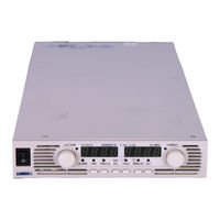
Lambda Genesys GENH 750W Technical Manual (81 pages)
Programmable DC Power Supplies
Brand:
Lambda
| Category:
Power Supply
| Size: 2 MB
Table of Contents
Table of Contents
4
Warranty
8
Safety Instructions
9
German Safety Instructions
11
Chapter 1 General Information
13
User Manual Content
13
Introduction
13
General Description
13
Models Covered
13
Features and Options
13
Multiple Output Power System
14
Control Via the Serial Communication Port
14
Analog Voltage Programming and Monitoring
14
Parallel Operation
14
Output Connections
14
Cooling and Mechanical Construction
15
Accessories
15
General
15
Serial Link Cable
15
Misc. Hardware
15
AC Cables
15
Rack Mount Kit
15
Serial Port Cables
15
Chapter 2 Specifications
16
Output Rating
16
Input Characteristics
16
Constant Voltage Mode
16
Constant Current Mode
16
Analog Progrmaming and Monitoring
16
Programming and Readback
17
Protective Functions
17
Front Panel
17
Environmental Conditions
17
Mechanical
17
Safety/Emc
17
Supplemental Characteristics
18
Outline Drawings
19
Chapter 3 Installation
20
General
20
Preparation for Use
20
Initial Inspection
20
Rack Mounting
21
To Install the Power Supply in a Rack
21
Rack Mount Slides
21
GENH/RM Rack Mounting Outline Drawings
22
Location Mounting and Cooling
22
Ac Source Requirements
22
Ac Input Power Connection
22
AC Input Connector, 750W Models
23
AC Input Cord
23
Turn-On Checkout Procedure
23
General
23
Prior to Operation
23
Constant Voltage Check
24
Constant Current Check
24
OVP Check
24
UVL Check
24
Foldback Check
24
Address Setting
25
Baud Rate Setting
25
Connecting the Load
25
Load Wiring
25
Current Carrying Capacity
25
Wire Termination
26
Noise and Impedance Effects
27
Inductive Loads
27
Making the Load Connections
27
Connecting Single Loads, Local Sensing (Default)
30
Connecting Single Loads, Remote Sensing
30
Connecting Multiple Loads, Radial Distribution Method
30
Multiple Loads Connection with Distribution Terminals
31
Grounding Outputs
31
Local and Remote Sensing
32
Sensing Wiring
32
Local Sensing
32
Remote Sensing
33
J2 Sense Connector Technical Information
33
Repackaging for Shipment
33
Chapter 4 Front and Rear Panel Controls and Connectors
34
Introduction
34
Front Panelcontrols and Indicators
34
Rear Panelconnections and Controls
36
Rear Panel Sw1 Setup Switch
37
SW1 Positions Functions
37
Resetting the Switch
38
Rear Panel J1 Programming and Monitoring Connector
38
Making J1 Connections
38
Chapter 5 Local Operation
41
Introduction
41
Standard Operation
41
Constant Voltage Mode
41
Constant Current Operation
42
Automatic Crossover
42
Over Voltage Protection (Ovp)
42
Setting the OVP Level
42
Activated OVP Protection Indications
42
Resetting the OVP Circuit
42
Under Voltage Limit
43
Setting the UVL Level
43
Foldback Protection
43
Setting the Foldback Protection
43
Resetting Activated Foldback Protection
43
Output On/Off Control
43
Output Shut-Off (So) Control Via Rear Panel J1 Connector
43
Enable/Disable Control Via
44
CV/CC Signal
44
Ps Ok Signal
45
Safe Start and Auto-Restart Mode
45
Automatic Start Mode
45
Safe Start Mode
45
Over Temperature Protection (Otp)
45
Last Setting Memory
45
Series Operation
46
Series Connection for Increased Output Voltage
46
Series Connection for Positive and Negative Output Voltage
47
Parallel Operation
48
Basic Parallel Operation
48
Advanced Parallel Operation
49
Daisy-Chain Shut-Off Connection
51
Front Panel Locking
51
Unlocked Front Panel
52
Locked Front Panel
52
Chapter 6 Remote Analog Programming
53
Introduction
53
Local/Remote Analog Control
53
Local/Remote Analog Indication
53
Remote Voltage Programming of Output Voltage and Current
54
Resistive Programming of Output Voltage and Current
55
Remote Monitoring of Output Voltage and Current
56
Chapter 7 Rs232 & Rs485 Remote Control
57
Introduction
57
Configuration
57
Default Setting
57
Address Setting
57
RS232 or RS485 Selection
57
Baud Rate Setting
57
Setting the Unit into Remote or Local Mode
57
RS232/458 Port at Local Mode
58
Front Panel in Remote Mode
58
Rear Panel Rs232/485 Connector
58
MD MODE OPTION (Factory Installed)
59
MD Mode Description
59
MD Mode Enable - Serial Communication Mode
59
MD Mode SRQ
59
Communication Collisions
59
MD Mode SRQ Retransmission
59
Connecting Power Supplies to Rs232 or Rs485 Bus
60
Single Power Supply
60
Multi Power Supply Connection to RS232 or RS485 BUS
61
Communication Interface Protocol
61
Data Format
61
Addressing
61
End of Message
61
Command Repeat
61
Checksum
61
Acknowledge
62
Error Message
62
Backspace
62
Error Messages
62
Command Set Description
62
General Guides
62
Command Set Categories
62
Initialization Control Commands
63
ID Control Commands
63
Output Control Commands
63
Global Output Commands
65
General
65
Single Byte Commands
66
General
66
Global Commands Without Response
66
Global Commands with Response
67
Addressed Commands with Response
67
Addressed Commands Without Response
68
Status Control Commands
70
Status, Error and Srq Registers
70
General Description
70
Status Registers
71
Conditional Registers
71
Service Request Enabled and Event Registers
72
Serial Communication Test Set-Up
75
Chapter 8 Isolated Analog Progamming Option
76
Introduction
76
Specifications
76
0-5V/0-10V Option
76
4-20Ma Option
76
Chapter 8 Isolated Analog Programming Option
76
Isolated Programming & Monitoring Connector
77
Setup and Operating Instructions
78
Setting up the Power Supply for 0-5V/0-10V Isolated Programming and Monitoring
78
Setting up the Power Supply for 4-20Ma Isolated Programming and Monitoring
78
Chapter 9 Maintenance
79
Introduction
79
Units under Warranty
79
Periodic Maintenance
79
Adjustment and Calibration
79
Parts Replacement and Repairs
79
Troubleshooting
79
Fuse Rating
80
Advertisement
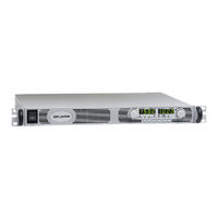
Lambda Genesys GENH 750W Technical Manual (79 pages)
Programmable dc Power Supply
Brand:
Lambda
| Category:
Power Supply
| Size: 2 MB
Table of Contents
Table of Contents
4
Warranty
8
Safety Instructions
9
German Safety Instructions
11
Chapter 1 General Information
13
User Manual Content
13
Introduction
13
General Description
13
Models Covered
13
Features and Options
13
Multiple Output Power System
14
Control Via the Serial Communication Port
14
Analog Voltage Programming and Monitoring
14
Parallel Operation
14
Output Connections
14
Cooling and Mechanical Construction
15
Accessories
15
General
15
Serial Link Cable
15
Misc. Hardware
15
AC Cables
15
Chapter 2 Specifications
16
Output Rating
16
Input Characteristics
16
Constant Voltage Mode
16
Constant Current Mode
16
Analog Progrmaming and Monitoring
16
Programming and Readback
17
Protective Functions
17
Front Panel
17
Environmental Conditions
17
Mechanical
17
Safety/Ems
17
Supplemental Characteristics
18
Outline Drawings
19
Chapter 3 Installation
20
General
20
Preparation for Use
20
Initial Inspection
20
Rack Mounting
20
To Install the Power Supply in a Rack
20
Rack Mount Slides
21
Location Mounting and Cooling
21
Ac Source Requirements
21
Ac Input Power Connection
21
AC Input Connector, 1500W Models
22
AC Input Connector, 750W Models
22
AC Input Cord
22
AC Input Wire Connection, 1500W Models
22
Turn-On Checkout Procedure
23
General
23
Prior to Operation
23
Constant Voltage Check
24
Constant Current Check
24
OVP Check
24
UVL Check
24
Foldback Check
24
Address Setting
25
Baud Rate Setting
25
Connecting the Load
25
Load Wiring
25
Current Carrying Capacity
25
Wire Termination
26
Noise and Impedance Effects
27
Inductive Loads
27
Making the Load Connections
27
Connecting Single Loads, Local Sensing (Default)
30
Connecting Single Loads, Remote Sensing
30
Connecting Multiple Loads, Radial Distribution Method
30
Multiple Loads Connection with Distribution Terminals
31
Grounding Outputs
31
Local and Remote Sensing
32
Sensing Wiring
32
Local Sensing
32
Remote Sensing
32
J2 Sense Connector Technical Information
33
Repackaging for Shipment
33
Chapter 4 Front and Rear Panel Controls and Connectors
34
Introduction
34
Front Panelcontrols and Indicators
34
Rear Panelconnections and Controls
36
Rear Panel Sw1 Setup Switch
37
SW1 Positions Functions
38
Resetting the Switch
38
Rear Panel J1 Programming and Monitoring Connector
38
Making J1 Connections
38
Chapter 5 Local Operation
41
Introduction
41
Standard Operation
41
Constant Voltage Mode
41
Constant Current Operation
41
Automatic Crossover
42
Over Voltage Protection (Ovp)
42
Setting the OVP Level
42
Activated OVP Protection Indications
42
Resetting the OVP Circuit
42
Under Voltage Limit
43
Setting the UVL Level
43
Foldback Protection
43
Setting the Foldback Protection
43
Resetting Activated Foldback Protection
43
Output On/Off Control
43
Output Shut-Off (So) Control Via Rear Panel J1 Connector
43
Enable/Disable Control Via
44
CV/CC Signal
44
Ps Ok Signal
44
Safe Start and Auto-Restart Modes
45
Automatic Start Mode
45
Safe Start Mode
45
Over Temperature Protection (Otp)
45
Last Setting Memory
45
Series Operation
45
Series Connection for Increased Output Voltage
46
Series Connection for Positive and Negative Output Voltage
47
Parallel Operation
48
Basic Parallel Operation
48
Advanced Parallel Operation
48
Daisy-Chain Shut-Off Connection
51
Front Panel Locking
51
Unlocked Front Panel
51
Locked Front Panel
51
Chapter 6 Remote Analog Programming
52
Introduction
52
Local/Remote Analog Control
52
Local/Remote Analog Indication
52
Remote Voltage Programming of Output Voltage and Current
53
Resistive Programming of Output Voltage and Current
54
Remote Monitoring of Output Voltage and Current
55
Chapter 7 Rs232 & Rs485 Remote Control
56
Introduction
56
Configuration
56
Default Setting
56
Address Setting
56
RS232 or RS485 Selection
56
Baud Rate Setting
56
Setting the Unit into Remote or Local Mode
56
RS232/458 Port at Local Mode
57
Front Panel in Remote Mode
57
Rear Panel Rs232/485 Connector
57
MD MODE OPTION (Factory Installed)
58
MD Mode Description
58
MD Mode Enable - Serial Communication Mode
58
MD Mode SRQ
58
Communication Collisions
58
MD Mode SRQ Retransmission
58
Connecting Power Supplies to Rs232 or Rs485 Bus
59
Single Power Supply
59
Multi Power Supply Connection to RS232 or RS485 BUS
60
Communication Interface Protocol
60
Data Format
60
Addressing
60
End of Message
60
Command Repeat
60
Checksum
60
Acknowledge
60
Error Message
61
Backspace
61
Error Messages
61
Command Set Description
61
General Guides
61
Command Set Categories
61
Initialization Control Commands
62
ID Control Commands
62
Output Control Commands
62
Global Output Commands
64
General
64
Single Byte Commands
65
General
65
Global Commands Without Response
65
Global Commands with Response
66
Addressed Commands with Response
66
Addressed Commands Without Response
67
Status Control Commands
69
Status, Error and Srq Registers
69
General Description
69
Status Registers
70
Conditional Registers
70
Service Request: Enable and Event Registers
71
Serial Communication Test Set-Up
74
Chapter 8 Isolated Analog Programming Option
75
Introduction
75
Specifications
75
0-5V/0-10V Option
75
4-20Ma Option
75
Isolated Programming & Monitoring Connector
76
Setup and Operating Instructions
77
Setting up the Power Supply for 0-5V/0-10V Isolated Programming and Monitoring
77
Setting up the Power Supply for 4-20Ma Isolated Programming and Monitoring
77
Chapter 9 Maintenance
78
Introduction
78
Units under Warranty
78
Periodic Maintenance
78
Adjustment and Calibration
78
Parts Replacement and Repairs
78
Troubleshooting
78
Fuse Rating
79
Advertisement
Related Products
Lambda 102A
Lambda 152A
Lambda 202A
Lambda 2U GENESYS 5kW
Lambda 303 Series
Lambda 500A
Lambda DLP/E Series
Lambda Categories
Power Supply
Measuring Instruments
Desktop
Water Pump
Laptop
More Lambda Manuals
Login
Sign In
OR
Sign in with Facebook
Sign in with Google
Upload manual
Upload from disk
Upload from URL