Table of Contents
Advertisement
INSTRUCTION
MANUAL
SPECIFICATIONS
Wingspan: 59 in [1500mm]
Length: 58 in [1475mm]
Weight: 6.5 – 7.25 lb [2950 – 3290 g]
2
Wing Area: 912 in
Wing Loading: 16– 18 oz/ft
WARRANTY
Great Planes
®
Model Manufacturing Co. guarantees this kit to
be free from defects in both material and workmanship at the
date of purchase. This warranty does not cover any component
parts damaged by use or modification. In no case shall Great
Planes' liability exceed the original cost of the purchased kit.
Further, Great Planes reserves the right to change or modify this
warranty without notice.
In that Great Planes has no control over the final assembly or
material used for final assembly, no liability shall be assumed nor
accepted for any damage resulting from the use by the user of
the final user-assembled product. By the act of using the
user-assembled product, the user accepts all resulting liability.
If the buyer is not prepared to accept the liability associated
with the use of this product, the buyer is advised to return
READ THROUGH THIS MANUAL BEFORE STARTING CONSTRUCTION. IT CONTAINS IMPORTANT
INSTRUCTIONS AND WARNINGS CONCERNING THE ASSEMBLY AND USE OF THIS MODEL.
®
Entire Contents © 2013 Hobbico,
Inc. All rights reserved.
Radio: 4-channel minimum
2
[58.8 dm
]
2
2
[49– 55 g /dm
]
Engine: .55-.65 [9 -10.5 cc]
with 5-6 servos
and standard size
receiver
Electric
Power:
this kit immediately in new and unused condition to the
place of purchase.
To make a warranty claim send the defective part or item to
Hobby Services at the address below:
Champaign IL 61822 USA
Include a letter stating your name, return shipping address, as
much contact information as possible (daytime telephone
number, fax number, e-mail address), a detailed description of
the problem and a photocopy of the purchase receipt. Upon
receipt of the package the problem will be evaluated as quickly
as possible.
™
two-stroke glow engine or .82
[13.5 cc] four-stroke glow engine
RimFire™ .80, (50-55-500)
Outrunner Brushless
Hobby Services
3002 N. Apollo Dr. Suite 1
Champaign, Illinois
(217) 398-8970, Ext 5
airsupport@greatplanes.com
GPMA1272 Mnl
Advertisement
Table of Contents

Related Manuals for GREAT PLANES U-Can-Do SF


Summary of Contents for GREAT PLANES U-Can-Do SF
-
Page 1: Instruction Manual
3002 N. Apollo Dr. Suite 1 Champaign IL 61822 USA In that Great Planes has no control over the final assembly or material used for final assembly, no liability shall be assumed nor Include a letter stating your name, return shipping address, as... -
Page 2: Table Of Contents
Open the “Airplanes” link, fl ying near full-scale aircraft and avoid fl ying near or over then select the U-Can-Do SF ARF. If there is new technical groups of people. information or changes to this model a “tech notice” box will appear in the upper left corner of the page. -
Page 3: Decisions You Must Make
Receiver U (HCAM6436) DECISIONS YOU MUST MAKE ❍ Hobbico LiFeSource AC/DC Balancing Charger 1S- This is a partial list of items required to fi nish the U-Can-Do SF 3S (HCAM6375) that may require planning or decision making before starting to build. Order numbers are provided in parentheses. -
Page 4: Brushless Motor Recommendations
❍ CG Machine (GPMR2400) This is the list of hardware and accessories required to fi nish ❍ Hobbico Flexible 18" Ruler Stainless Steel the U-Can-Do SF. Order numbers are provided in parentheses: (HCAR0460) ❍ R/C foam rubber 1/4" [6mm] (HCAQ1000) ❍... -
Page 5: Building Stand
Fax: (217) 398-7721 E-mail: airsupport@greatplanes.com ORDERING REPLACEMENT PARTS Replacement parts for the Great Planes U-Can-Do SF are available using the order numbers in the Replacement Parts List that follows. The fastest, most economical service can be provided by your hobby dealer or mail-order company. -
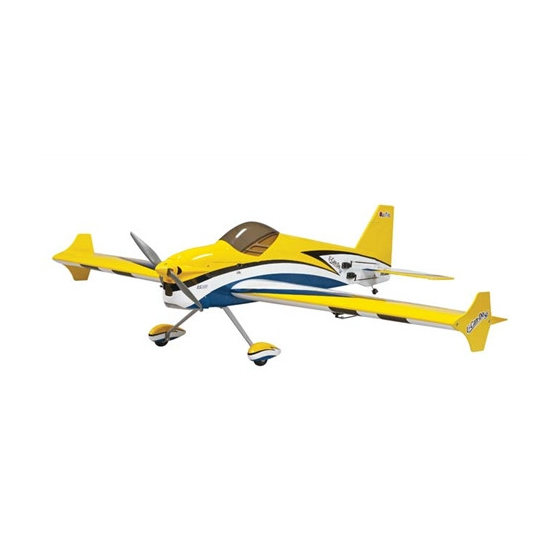
Page 6: Kit Contents
KIT CONTENTS Kit Contents Cowl Fuselage Canopy Hatch Wing / Ailerons Vertical Fin / Rudder Horizontal Stabilizer Elevator Halves Fuel Tank Spinner Engine Mount Landing Gear Wheels Side Force Generator PREPARATIONS INSTALL THE AILERON SERVOS, ❏ PUSHRODS AND BELLY PAN 1. - Page 7 perpendicular with the servo case. Cut three arms from each servo arm leaving one arm on each servo that matches the photo. Enlarge the outer hole of each remaining arm with a 5/64" [2mm] drill bit. Attach a 12" [305mm] servo extension to each servo.
- Page 8 the control horns over the hardwood blocks in the ailerons Servo Horn (if you cannot see them, hold the aileron at a shallow angle in good lighting or use a small pin to puncture the covering). When satisfi ed, use a felt-tip pen to mark the location of the control horn mounting holes onto the aileron.
- Page 9 ❏ 11. Locate the two nylon wing dowels. Coat the grooved ends with epoxy and fi t the dowels into the holes at the leading edge of the wing as far as they will fi t into the holes. Wipe ❏...
-
Page 10: Install The Tail Section
INSTALL THE TAIL SECTION Pull the stab from the fuselage and remove the covering 1/16" [1.6mm] inside your lines using the same technique you used on the wing. ❏ 3. Coat the exposed wood with 30-minute epoxy (although messy, a more reliable glue joint can be attained if you also coat the inside edges of the stab pocket). - Page 11 Coat the inside of the fi n slot with epoxy as well as the rudder ❏ 5. Temporarily install the vertical fi n and rudder into the end of the tail wheel wire and the nylon tab. Fit the vertical slot in the fuselage.
-
Page 12: Install The Main Landing Gear
❏ 9. Locate the mounting blocks under the covering in the elevator halves for the elevator control horns. Position a control horn onto each elevator half over these mounting ❏ 11. Apply a drop or two of oil onto the tail wheel axle and blocks and mark the locations for the control horn mounting slide on the tail wheel. -
Page 13: Install The Power System
marks. Be sure to drill the holes as shown in the picture. It is recommended to start with a small drill bit and work your way up in size to 11/64" [4.4mm]. Doing this will improve accuracy in the positioning of the holes and will reduce the amount of tear-out from the backside of the holes. - Page 14 Press four 6-32 blind nuts into the holes as shown and apply some glue around each nut to prevent them from coming loose. ❏ ❏ 4. Glue the two rear pieces together. Assemble the rest 7. Install the aluminum ‘X’ mount and prop adapter onto of the mount being sure to thoroughly glue all the joints your brushless motor using the screws included with the together.
- Page 15 make the extension shown you will need to purchase: W.S. ® ® Deans Female Ultra Plug w/Pigtail (WSDM3010) and W.S. ® ® Deans Male Ultra Plug (2) (WSDM1302). To make the extension, cut the wires on the pigtail to a length of 3" [76mm] and strip the insulation 3/16"...
-
Page 16: Glow Engine
❏ 1. If you are mounting a .55AX or .65AX engine in the angled orientation, drill a hole for the throttle pushrod in the fi rewall in the location shown using an 11/64" [4.4 mm] drill bit. If you are installing a different engine or an inverted engine, you will need to locate this hole according to the position of the throttle arm on your carburetor. - Page 17 ❏ ❏ 4. Insert the pushrod tube through the hole you drilled in 6. Drill 11/64" [4.4mm] holes at the angled mounting pattern the fi rewall and into the notch in the fuel tank support. The on the fi rewall. For accuracy and to avoid tearing the wood pushrod tube should stick out past the fi...
- Page 18 ❏ 9. Loop the strap through the slots behind the fuel tank support. Fit the fuel tank onto the fuel tank support with the fuel tank neck through the hole in the fi rewall (be sure that the correct side of the tank is facing up). Draw the strap ends around the tank and confi...
- Page 19 washers, four #6 fl at washers and thread locking compound. The engine mount should be angled down and to the right. Fit your engine between the mount halves and slide them together against the crankcase. Remove the engine and fi nish tightening the mount screws. ❏...
-
Page 20: Install The Receiver, Battery, And Switch
throttle servo perpendicular to the servo case (be sure to install the servo arm screw). Adjust the carb barrel so that it is close to 50% open and tighten the set screw in the screw- lock connector. Test the operation of the throttle using your transmitter and confi... -
Page 21: Finish The Model
receptable fi ts well in front of the switch. Note: If you are using a LiFe receiver pack then the charge jack receptable should be used for monitoring pack voltage, or charging in conjunction with the balancing lead. Do not attempt to charge a LiFe battery through this jack without also conencting to the balance lead! The balancing connector will remain accessible through the canopy hatch. - Page 22 tape pieces exactly where the cowl mounting screw holes will be drilled. The holes should be located in the center of the thickness of the fi rewall. Use a ruler to draw straight lines exactly 4" [102mm] long aft of your cowl screw hole marks. ❏...
- Page 23 fi t your prop. The cone should not contact the prop at any point in the cut out. ❏ 9. Admire your completed U-Can-Do SF ARF! Prepare to move on to the fi nal sections for applying the decals, getting the control throws set and the plane balanced.
-
Page 24: Optional Side Force Generators
Optional Side Force Generators Side force generators are included as an optional addition. The side force generators are designed to reduce wing walking in high-alpha maneuvers and reduce the amount of rudder input needed for knife-edge fl ight. The side force generators are easily installed and removed at your fl... -
Page 25: Set The Control Throws
fi rst fl ights. If, after you have FULL ELEVATOR become accustomed to the way the U-Can-Do SF fl ies, you THROTTLE MOVES DOWN would like to change the throws to suit your taste, that is fi ne. -
Page 26: Proper Pushrod Hookup; Avoiding Flutter, Maximizing Servo Output Torque
Preferred Proper Pushrod Hookup; Pushrod Hookup Avoiding Flutter, Maximizing Servo Output Torque SERVO ARM “Closest in” “Farthest out” OFFSET on servo arm on control horn Here is an optimum pushrod setup—the pushrod is “close in” on the servo arm and “far out” on the control horn. This situation gives the greatest mechanical advantage of the servo over the control surface which will increase the servo’s CONTROL... -
Page 27: Balance The Model (C.g.)
fl ying, and at other times as recommended by model installed (ready to fl y) and an empty fuel tank, place the radio manufacturer. the model on a Great Planes CG Machine upside down, or lift it at the balance point you marked. ❏... -
Page 28: Balance Propellers
We use a Top Flite Precision Magnetic Prop Balancer or otherwise get into the running propeller. (TOPQ5700) in the workshop and keep a Great Planes Fingertip Prop Balancer (GPMQ5000) in our fl ight box. Make all engine adjustments from behind the rotating propeller. -
Page 29: Radio Control
fl own. To help avoid this, a check list is provided to The U-Can-Do SF is a great-fl ying model that fl ies smoothly make sure these important areas are not overlooked. Many and predictably. -
Page 30: Takeoff
fl y more smoothly at reduced speeds. mind that being tail heavy is not always the best way to go. Take it easy with the U-Can-Do SF for the fi rst few fl ights, Propeller thrust and thrust vectoring need to be considered gradually getting acquainted with it as you gain confi... - Page 31 Higher RPM engines such as a .46 two-stoke require a low Inverted Flat Spins pitch propeller and lower RPM motors such as a 1.60 will This is the same as the up-right fl at spin except most planes require a higher pitch propeller. If you feel that the effectiveness like to spin in the opposite direction, for example: right rudder of the tail surfaces is not enough, try a smaller propeller with and down elevator.
- Page 32 rudder and elevator to keep the nose pointing straight up. Be Pinwheel patient as this maneuver will take a while to learn. Torque Roll This is the same as the vertical hover but without the use of right aileron to keep the model from rolling. If needed, you can use a little left aileron to speed the roll up.
Need help?
Do you have a question about the U-Can-Do SF and is the answer not in the manual?
Questions and answers