Table of Contents
Advertisement
Quick Links
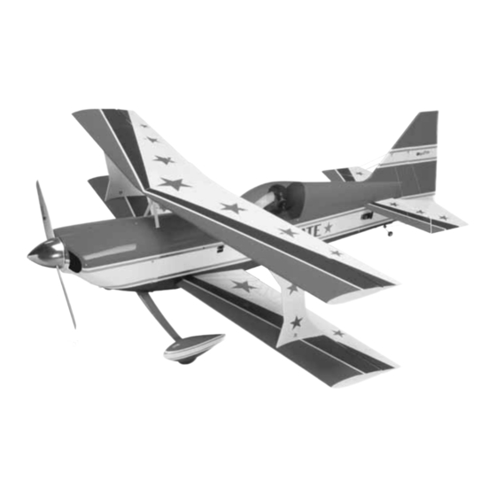
Wingspan: 65 in [1650mm]
Wing Area: 1446 sq in [93dm
Weight: 12 – 13.5 lb [5440 – 6120g]
Wing Loading: 19 – 22 oz/sq ft [58 – 67g/dm
Length: 72 in [1830mm]
Radio: 4-channel radio (minimum), 7-channel or greater computer
radio with mixing capabilities (preferred).
Engine: 1.60 cu in [26cc] two-stroke, 43cc gasoline engine
Great Planes
Model Manufacturing Co. guarantees this kit to be free from defects in both material and workmanship at the date of purchase.
®
This warranty does not cover any component parts damaged by use or modification. In no case shall Great Planes' liability exceed the
original cost of the purchased kit. Further, Great Planes reserves the right to change or modify this warranty without notice.
In that Great Planes has no control over the final assembly or material used for final assembly, no liability shall be assumed nor accepted for
any damage resulting from the use by the user of the final user-assembled product. By the act of using the user-assembled product, the user
accepts all resulting liability.
If the buyer is not prepared to accept the liability associated with the use of this product, the buyer is advised to return this kit
immediately in new and unused condition to the place of purchase.
To make a warranty claim send the defective part or item to Hobby Services at the address below:
Include a letter stating your name, return shipping address, as much contact information as possible (daytime telephone number, fax number,
e-mail address), a detailed description of the problem and a photocopy of the purchase receipt. Upon receipt of the package the problem will
be evaluated as quickly as possible.
READ THROUGH THIS MANUAL BEFORE STARTING
CONSTRUCTION. IT CONTAINS IMPORTANT INSTRUCTIONS
AND WARNINGS CONCERNING THE ASSEMBLY AND
USE OF THIS MODEL.
© Copyright 2005
INSTRUCTION MANUAL
2
]
2
]
3002 N. Apollo Dr., Suite 1
WARRANTY
Hobby Services
Champaign, IL 61822
USA
Champaign, Illinois
(217) 398-8970, Ext 5
airsupport@greatplanes.com
GPMZ0192 for GPMA1307 V1.0
Advertisement
Table of Contents

Related Manuals for GREAT PLANES ultimate!


Summary of Contents for GREAT PLANES ultimate!
-
Page 1: Instruction Manual
Further, Great Planes reserves the right to change or modify this warranty without notice. In that Great Planes has no control over the final assembly or material used for final assembly, no liability shall be assumed nor accepted for any damage resulting from the use by the user of the final user-assembled product. -
Page 2: Table Of Contents
AMA..................2 Any model called the “Ultimate” better be as good as it SAFETY PRECAUTIONS............2 sounds. The Great Planes Ultimate has been designed with DECISIONS YOU MUST MAKE ..........3 an eye on high performance and light weight. You will find Radio Equipment .............3 that there is not much this airplane cannot do. -
Page 3: Decisions You Must Make
Vacuum the parts and the work area thoroughly after working with fiberglass parts. The Great Planes “Ultimate” has been tested and flown with the O.S. 1.60 cu in two-stroke [26cc] glow engine and the Fuji-IMVAC BT-43EIS [43cc] gasoline engine. If you choose... -
Page 4: Additional Items Required
ADDITIONAL ITEMS REQUIRED This is a number six screw that is 3/4" [19mm] long. Required Hardware & Accessories • Machine screws (MS) are designated by a number, threads per inch, and a length. For example, 4-40 x This is the list of hardware and accessories required to finish 3/4"... -
Page 5: Metric Conversions
COMMON ABBREVIATIONS ORDERING REPLACEMENT PARTS Fuse = Fuselage Stab = Horizontal Stabilizer Fin = Vertical Fin LE = Leading Edge Replacement parts for the Great Planes “Ultimate” ARF TE = Trailing Edge available using order numbers LG = Landing Gear Replacement Parts List that follows. -
Page 6: Kit Inspection
If any parts are missing or are not of acceptable quality, or if you need assistance with assembly, contact Product Support. When reporting defective or missing parts, use the part names exactly as they are written in the Kit Contents list. Great Planes Product Support 3002 N. Apollo Drive, Suite 1 Champaign, IL 61822 Telephone: (217) 398-8970, ext. -
Page 7: Preparations
PREPARATIONS ❏ 1. If you have not done so already, remove the major parts of the kit from the box and inspect for damage. If any parts are damaged or missing, contact Product Support at the address or telephone number listed in the “Kit Inspection”... -
Page 8: Install The Aileron Servo & Pushrods
Install the Aileron Servos & Pushrods ❏ ❏ ❏ ❏ 5. Install the servo into the servo opening. Drill through the servo mounting holes with a 1/16" [1.6mm] drill bit. Remove the servo from the servo opening. Install and then remove a servo mounting screw into each of the holes you have drilled. -
Page 9: Join The Bottom Wing
❏ ❏ ❏ ❏ 7. Thread a 4-40 nut onto a 4-40 x 5-3/4" [146mm] ❏ ❏ ❏ ❏ threaded rod approximately twenty turns. Slide a silicone clevis 8. After the rod has cooled, install a clevis retainer onto a threaded 4-40 metal clevis. Then, thread the retainer onto the clevis you have just soldered. - Page 10 ❏ ❏ 2. Test fit the plywood and balsa wing joiner into the 6. Place the plywood wing bolt mounting plates in joiner pocket of both wing halves. When you are satisfied position on the bottom of the wing, over the wing bolt holes. with the fit of the joiners, glue the joiner into the bottom wing When positioning the plates be sure the widest part of the panels with 30-minute epoxy.
-
Page 11: Install The Center Cabanes & "I" Struts
cabanes apply a couple of drops of Threadlocker to the Install the Center Cabanes & “I” Struts screws. Do not fully tighten the screws; just make them snug for now. ❏ 3. Insert the cabane for the left side of the fuselage into the slots on the top, left side of the fuselage. - Page 12 ❏ ❏ ❏ ❏ 6. Locate one of the knurled knobs and an 8-32 x 2" [51mm] threaded rod. ❏ 10. Repeat steps 6-9 for each of the knurled knobs and threaded rods, completing the assembly for each of the openings in the “I”...
-
Page 13: Assemble The Top Wing
[230mm] from the wing tips. Cut the covering away from these holes. ❏ 13. Mount the bottom wing to the fuselage with two 1/4-20 x 2" [51mm] wing bolts. ❏ 2. Locate the aluminum wing rib. Test fit the components of the top wing by sliding the aluminum rib onto the dowels in the right wing panel. -
Page 14: Mount The Belly Pan
ASSEMBLE THE FUSELAGE ❏ 1. If you have removed the wings, re-install them to the fuselage. Cut the covering from the back of the fuselage to reveal the slot for the horizontal stabilizer and the vertical fin. ❏ 4. Once the wing is attached to the struts, install a 4-40 x 1/2"... -
Page 15: Install The Elevators & Rudder
❏ 6. Glue the stab in place making sure that the stab is Build the Carry Handle properly aligned. Allow the glue to harden before continuing with step #7. This kit comes with a convenient carrying handle for the fuselage. In addition to its use as a handle, when installed, it will allow you to turn the plane upside-down on the workbench without flexing or bending the center cabanes. -
Page 16: Assemble The Landing Gear & Wheel Pants
❏ 3. When properly assembled, four slots are formed in the handle as shown. ❏ 1. Bolt the landing gear to the fuselage with 6-32 x 1" [25mm] socket-head cap screws, #6 lock washers and #6 flat washers. When installing the landing gear, be sure the gear sweeps towards the back of the fuselage. - Page 17 ❏ 8. Locate the nylon tail wheel bushing and glue it in place ❏ ❏ 5. Apply a couple of drops of threadlocker onto two in the hole. 6-32 x 1/4 [6mm] socket-head cap screws. Then, thread them in the 3/32" [2.4mm] wheel collars. Slide a wheel collar onto the axle followed by a wheel and the remaining wheel collar.
-
Page 18: Install The Elevator & Rudder Servos
The servo. Next, mark the position the wire should be cut to fit Great Planes 1-1/2" [38mm] aluminum servo arm into the solder clevis. Remove all of the pushrod (GPMM1105) works well for this. -
Page 19: Install The Tail Wires
the elevator and servo. Follow the same procedure for the rudder pushrod. ❏ 8. Using the same method, install the pushrod linkage to the opposite elevator and the rudder (if a second rudder is to be used). ❏ 2. The location of the wire attachment points are located with a pin hole in the stab and fin. -
Page 20: Install The Engine
Installation instructions for the O.S. 1.60 two-cycle engine ❏ 6. Located on the bottom of the fuselage are two plywood plates. Drill a 1/16" [1.6mm] hole in the center of each of the plates. Install a #2 x 3/8" [9.5mm] screw and a #2 washer ❏... - Page 21 4-40 x 1/4" [6mm] socket-head cap screw [178mm]. Mark the location of the engine on the mount. The onto the outer hole of the servo arm and the throttle servo Great Planes “Dead Center ™ ” Hole Locator (GPMR8130) arm.
- Page 22 ❏ 2. Locate the 1/8" x 6" [3 x 152mm] hardwood dowel. Apply epoxy into the holes and on the dowel. Insert the hardwood dowel into the hole. Cut the dowel flush with the surface. Do this for all four holes. Apply a few drops of thin CA to fuelproof the ends of the dowels.
-
Page 23: Install The Fuel Tank
❏ 8. Install the ignition cut-off switch (refer to your engine instructions for switch recommendations) as close to the engine as possible. The bottom of the fuselage is a good location for this. You may wish to create a small plywood mounting plate to mount the switch to the fuselage. -
Page 24: Install The Cowl
Note: If using fuel line barbs (as recommended for gas engines), replace the aluminum fuel tubes with 1/8" [3.2mm] brass tubing (not included). Cut the brass tubes to the correct ❏ length, and then solder the barbs onto one end of the tubes. 2. -
Page 25: Install The Receiver, Battery & Complete The Aileron Connections
❏ 7. Cut the cowl as needed to allow clearance for the muffler and needle valve, access to the glow plug, etc. When you have completed this, mount the cowl with five 1/2" [13mm] screws and five #4 flat washers. As you can see here, the cowl tool has provided the proper spacing for the spinner. - Page 26 ❏ 3. Install the battery and receiver onto the tray. Protect the battery and receiver from vibration by putting 1/4" [254mm] R/C foam rubber between them. Cut the Velcro ® length and use it to hold the receiver and battery in place. Push the receiver antenna wire into the antenna tube inside of the fuselage.
-
Page 27: Finishing Touches
FINISHING TOUCHES GET THE MODEL READY TO FLY ❏ 1. Paint the cockpits flat black. After the paint has dried. Check the Control Directions apply the instrument panel decal. ❏ ❏ 2. If you will be installing a pilot, install it into the cockpit. 1. -
Page 28: Balance The Model (C.g.)
If spinner weight is not practical or is not enough, Balance the Model (C.G.) use Great Planes (GPMQ4485) “stick-on” lead. A good place to add stick-on nose weight is to the firewall (don’t attach weight to the cowl–it is not intended to support More than any other factor, the C.G. -
Page 29: Balance The Model Laterally
We use a Top Flite Precision Magnetic Prop Balancer ™ (TOPQ5700) in the workshop and keep a Great Planes Fingertip Prop Balancer (GPMQ5000) in our flight box. PREFLIGHT Ground Check Identify Your Model If the engine is new, follow the engine manufacturer’s... -
Page 30: Engine Safety Precautions
General ENGINE SAFETY PRECAUTIONS 1) I will not fly my model aircraft in sanctioned events, air shows, or model flying demonstrations until it has been Failure to follow these safety precautions may result proven to be airworthy by having been previously, in severe injury to yourself and others. -
Page 31: Check List
❏ 19. Cycle your receiver battery pack (if necessary) and CHECK LIST make sure it is fully charged. ❏ 20. If you wish to photograph your model, do so before your first flight. ❏ 21. Range check your radio when you get to the flying field. During the last few moments of preparation your mind may be elsewhere anticipating the excitement of the first flight. -
Page 32: Takeoff
it is important to use good throttle management. Full power Takeoff down lines could result in over stressing of the aircraft. Before you get ready to takeoff, see how the model handles Landing on the ground by doing a few practice runs at low speeds on the runway. -
Page 33: Fuji-Imvac Bt-43 Eis Engine Mounting Template
Fuji-IMVAC BT-43 EIS Engine Mounting Template O.S. 1.60 Engine Mounting Template... - Page 35 Great Planes 1/3-Scale Christen Eagle II ARF True to the homebuilt original, the Christen Eagle II pushes the design envelope – making it Great Planes’ most realistic bipe ever. In just 25-30 hours this bird is flight-ready, with scale details such as fairings, struts and cowl made of...
- Page 36 BUILDING NOTES Kit Purchased Date: _______________________ Date Construction Finished: _________________ Where Purchased:_________________________ Finished Weight: __________________________ Date Construction Started: __________________ Date of First Flight: ________________________ FLIGHT LOG...
Need help?
Do you have a question about the ultimate! and is the answer not in the manual?
Questions and answers