Table of Contents
Advertisement
Quick Links
Download this manual
See also:
Installation Manual
Advertisement
Table of Contents
Troubleshooting

Related Manuals for Sun Microsystems Netra ct


Summary of Contents for Sun Microsystems Netra ct
- Page 1 Netra ct Server Service Manual ™ Sun Microsystems, Inc. 901 San Antonio Road Palo Alto, CA 94303 U.S.A. 650-960-1300 Part No. 806-3296-11 February 2001, Revision A Send comments about this document to: docfeedback@sun.com...
- Page 2 Sun, Sun Microsystems, the Sun logo, AnswerBook2, docs.sun.com, Netra, and Solaris are trademarks, registered trademarks, or service marks of Sun Microsystems, Inc. in the U.S. and other countries. All SPARC trademarks are used under license and are trademarks or registered trademarks of SPARC International, Inc.
-
Page 3: Table Of Contents
1.4.2 Cold-Swappable FRUs 1-5 Device Names 1-5 1.5.1 Device Names for I/O Card Slots in the Netra ct Servers 1-5 1.5.2 Device Names for Hard Disk Drives 1-6 Powering the Server Off and On 2-1 Powering On the Server 2-1... - Page 4 Troubleshooting the System Using the Remote System Control (RSC) 4-14 Troubleshooting a Power Supply Using the Power Supply Unit LEDs 4-14 4.7.1 Troubleshooting the Power Supply Unit in the Netra ct 400 Server 4-15 4.7.2 Troubleshooting the Power Supply Units in the Netra ct 800...
- Page 5 Rear-Access Models 6-39 6.2.1 Front I/O Card and I/O Rear Transition Card 6-40 6.2.2 Alarm Rear Transition Card (Netra ct 800 Server Only) 6-51 Removing and Replacing Hard Disk Drives and Removeable Media 7-1 Hard Disk Drive 7-1 7.1.1 Removing a Hard Disk Drive 7-2 7.1.2...
- Page 6 10.1 Front-Access Models 10-1 10.1.1 CPU Card 10-2 10.1.2 CPU Front Transition Card 10-10 10.1.3 CPU Shunt Card (Netra ct 800 Server Only) 10-17 10.2 Rear-Access Models 10-19 10.2.1 CPU Card 10-19 10.2.2 CPU Rear Transition Card 10-26 Removing and Replacing Cold-Swappable Subassemblies 11-1 11.1...
- Page 7 11.3 SCSI Termination Board (Netra ct 800 Server Only) 11-7 11.3.1 Removing a SCSI Termination Board 11-7 11.3.2 Replacing a SCSI Termination Board 11-8 11.4 Power Distribution Unit 11-8 11.4.1 Removing the Power Distribution Unit 11-10 11.4.2 Replacing the Power Distribution Unit 11-15 11.5...
- Page 8 CPU Front Transition Card, Netra ct 400 Server A-12 A.3.1 SCSI (VHDC) A-13 A.3.2 Parallel Port A-14 A.3.3 Ethernet B Port A-15 A.3.4 TTY B A-16 CPU Rear Transition Card A-17 A.4.1 Parallel Port A-19 A.4.2 TTY A A-20 A.4.3 TTY B A-21 A.4.4...
- Page 9 To Use a Solaris Workstation B-3 To Use a PC Laptop B-5 C. Error Messages C-1 scsb Error Messages C-2 Anticipated Hardware Failure C-8 C.2.1 Transient Interrupts C-8 C.2.2 Soft Hang C-8 I2C Complaints C-9 Bus Busy Complaints C-10 D. System Specifications D-1 Physical Specifications D-1 Electrical Specifications D-2 Environmental Specifications D-3...
- Page 10 Netra ct Server Service Manual • February 2001...
- Page 11 Attaching the Antistatic Wrist Strap 1-2 FIGURE 1-1 Front-Access and Rear-Access Models 1-3 FIGURE 1-2 Locating the Power Supply Locking Mechanism on the Netra ct 800 Server 2-2 FIGURE 2-1 Locating the Power Supply Locking Mechanism on the Netra ct 400 Server 2-3 FIGURE 2-2...
- Page 12 FIGURE 6-22 Drive Bay Cover Locations 7-3 FIGURE 7-1 Locating the Hard Disk Drive LEDs on the System Status Panel (Netra ct 800 Server) 7-6 FIGURE 7-2 Removing the Removeable Media Module from a Netra ct 800 Server 7-11 FIGURE 7-3...
- Page 13 FIGURE 8-10 Locating the Main Air Filter (Netra ct 400 Server) 8-13 FIGURE 8-11 Locating the Power Supply Unit LEDs on the System Status Panel (Netra ct 800 Server) 8- FIGURE 8-12 Unlocking a Power Supply Unit 8-16 FIGURE 8-13...
- Page 14 FIGURE 10-17 Connectors on the CPU Card 10-26 FIGURE 10-18 Locating the CPU Rear Transition Card in the Rear-Access Model of a Netra ct 800 Server FIGURE 10-19 (Top View) 10-28 Locating the CPU Rear Transition Card in the Rear-Access Model of a Netra ct 400 Server...
- Page 15 FIGURE 11-12 Loosening the Front-Access Cable Screws 11-18 FIGURE 11-13 Removing or Replacing a Power Supply Unit From a Netra ct 800 Server 11-20 FIGURE 11-14 Removing or Replacing a Power Supply Unit From a Netra ct 400 Server 11-21...
- Page 16 FIGURE A-18 RJ-45 Ethernet Connector Diagram A-22 FIGURE A-19 RJ-45 Ethernet Connector Diagram A-23 FIGURE A-20 Connector Ports in the Alarm Card in Netra ct 800 Server A-25 FIGURE A-21 Alarm Port A-26 FIGURE A-22 RJ-45 Ethernet Connector Diagram A-27...
- Page 17 Tables Device Names for I/O Card Slots in the Netra ct 800 Server 1-5 TABLE 1-1 Device Names for I/O Card Slots in the Netra ct 400 Server 1-6 TABLE 1-2 System Status Panel LEDs for the Netra ct 800 Server 4-4...
- Page 18 Ethernet B Connector Pinouts, CPU FTC for the Netra ct 400 Server A-15 TABLE A-9 TTY B Port Pinouts, CPU FTC for the Netra ct 400 Server A-16 TABLE A-10 Parallel Port Pinouts, CPU RTC A-19 TABLE A-11 TTY A Port Pinouts, CPU RTC A-20...
- Page 19 Environmental Specifications D-3 TABLE D-5 Permissible Memory Configurations on the CPU Card E-1 TABLE E-1 Memory Sizes and Part Numbers E-2 TABLE E-2 Tables...
- Page 20 Netra ct Server Service Manual • February 2001...
-
Page 21: Safety And Compliance
LAN fundamentals and with networking in general. Before performing the procedures described in this book, you should have completed the installation and setup of the Netra ct server as described in the Netra ct Server Installation Guide. Safety and Compliance... - Page 22 Chapter 12 gives the illustrated parts breakdown for the Netra ct server. Part VI “Appendixes, Glossary, and Index” Appendix A lists the connector pinouts for the cards in the Netra ct server. Appendix B provides instructions for connecting a terminal console to the server.
-
Page 23: Typographic Conventions
Using UNIX Commands This document contains only limited information on basic UNIX® commands and procedures such as shutting down the system, booting the system, and configuring devices. See one or more of the following for this information: Solaris Handbook for Sun Peripherals (shipped in AnswerBook2™ form, available in printed form as an at-cost option) AnswerBook online documentation for the Solaris software environment Other software documentation that you received with your system... -
Page 24: Related Documentation
Depending on the options you might have purchased for your machine, you might have also received manuals for network interface cards. As mentioned above, as a Netra ct server purchaser, you receive a suite of online documentation for the Solaris operating environment. -
Page 25: Sun Welcomes Your Comments
Ordering Sun Documentation Fatbrain.com, an Internet professional bookstore, stocks select product documentation from Sun Microsystems, Inc. For a list of documents and how to order them, visit the Sun Documentation Center on Fatbrain.com at: http://www.fatbrain.com/documentation/sun... - Page 26 Netra ct Server Service Manual • February 2001...
-
Page 27: Part I Preparing For Service
Preparing for Service P A R T Preparing for FRU Installation and Replacement Chapter 1 Powering the Server Off and On Chapter 2 Handling Cards and Assemblies Chapter 3... - Page 28 Netra ct Server Service Manual...
-
Page 29: Preparing For Fru Installation And Replacement
Preparing for FRU Installation and Replacement This chapter describes the steps you need to take before you install, remove, or replace a field-replaceable unit (FRU) in your Netra ct server. This chapter is divided into the following sections: “Tools Required” on page 1-1 “Attaching the Antistatic Wrist Strap”... -
Page 30: Figure 1-1 Attaching The Antistatic Wrist Strap
4. Peel the liner from the copper foil at the opposite end of the wrist strap and attach the copper end of the strap to a bare metal area on the Netra ct server or on the chassis. -
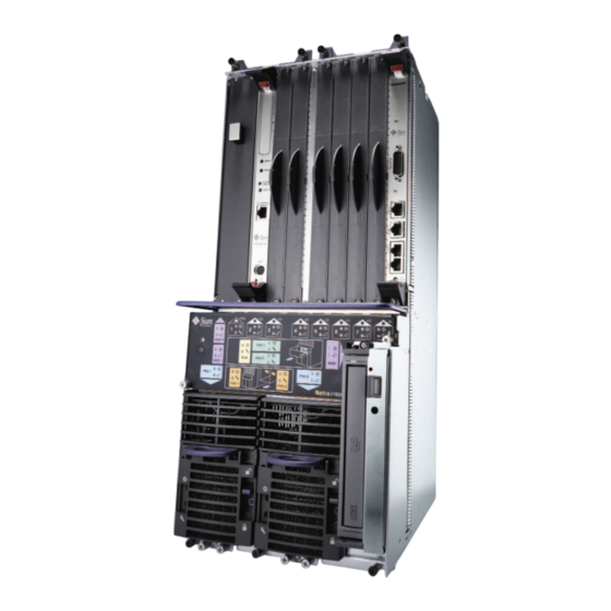
Page 31: Determining If You Have A Front-Access Or Rear-Access Model
Determining If You Have a Front-Access or Rear-Access Model If you are not sure whether you have a front-access or a rear-access model, go to the front of the chassis and look at the top part of the chassis. If you see the DC connectors at the front of the chassis, then you have a front-access model ( FIGURE 1-2 If you do not see DC connectors at the front of the chassis, and metal filler plates... -
Page 32: Fru Categories
FRU Categories In general, the FRUs in a Netra ct server can be divided into two categories: Hot-installable/replaceable (referred to hereafter as hot-swappable), meaning that you can install or remove and replace a FRU while the server is running, without interrupting the operation of the server. -
Page 33: Cold-Swappable Frus
Device Names for I/O Card Slots in the Netra ct Servers gives the device names for the I/O card slots in the Netra ct 800 server and TABLE 1-1 gives the device names for the I/O card slots in the Netra ct 400 server. -
Page 34: Device Names For Hard Disk Drives
Device Name /devices/pci@1f,0/pci@1/pci@1/pci@8 /devices/pci@1f,0/pci@1/pci@1/pci@f /devices/pci@1f,0/pci@1/pci@1/pci@e /devices/pci@1f,0/pci@1/pci@1/pci@d 1.5.2 Device Names for Hard Disk Drives Following are the device names for the hard disk drives installed in the Netra ct servers: HDD 0—c0t0d0 HDD 1—c0t1d0 Netra ct Server Service Manual • February 2001... -
Page 35: Powering The Server Off And On
I/O slot, you must manually reset the I/O slot to full hot swap after rebooting or powering your server on and off. Note – You can also power the Netra ct server on and off through the alarm card using the poweroff and poweron commands. Refer to the Remote System Control (RSC) User’s Guide For the Netra ct Server Alarm Card for more information. -
Page 36: Figure 2-1 Locating The Power Supply Locking Mechanism On The Netra Ct 800 Server
Locating the Power Supply Locking Mechanism on the Netra ct 800 Server FIGURE 2-1 Netra ct Server Service Manual • February 2001... -
Page 37: Figure 2-2 Locating The Power Supply Locking Mechanism On The Netra Ct 400 Server
2. Locate the system status panel. The location of the system status panel in the Netra ct 800 server and Netra ct 400 server is illustrated in FIGURE 2-3... -
Page 38: Figure 2-3 System Status Panel Locations
3. Locate the system power button on the system status panel and press the system power button to power on the server. shows the system power button location for the Netra ct 800 server, and FIGURE 2-4 shows the system power button location for the Netra ct 400 server. -
Page 39: Figure 2-4 System Power Button And System Power Led Locations (Netra Ct 800 Server)
When you first power-on the Netra ct server, some or all of the green Power LEDs on the system status panel flash on and off for several seconds: If the diag-switch variable is set to true and the diag-level variable is set to max in the OpenBoot™... -
Page 40: Powering Off The Server
4. Verify that the system power LED on the system status panel is on, indicating that the system is completely powered on. shows the system power LED location for the Netra ct 800 server, and FIGURE 2-4 shows the system power LED location for the Netra ct 400 server. - Page 41 2. Go to the front of the Netra ct server and locate the system status panel. The location of the system status panels in the Netra ct 800 server and Netra ct 400 server is illustrated in FIGURE 2-3 3.
- Page 42 2-6 shows the system power LED location for the FIGURE 2-5 Netra ct 400 server. 6. If you want to completely power off the Netra ct server, push the purple power supply unit locking mechanism(s) up into the unlocked ( ) position (see...
-
Page 43: To Perform A Software Power Off
4. At the ok prompt, enter: ok power-off 5. Go to the front of the Netra ct server and locate the system status panel (see on page 2-4). FIGURE 2-3 The location of the system status panel in the Netra ct 800 server and Netra ct 400... - Page 44 Note – You must unlock the locking mechanism on both power supply unit(s) on the Netra ct 800 server in order to completely power off that server. The green power ( ) LED(s) on the power supply unit(s) should go off (unlit), indicating that the system is now completely powered off.
-
Page 45: Handling Cards And Assemblies
Handling CompactPCI Cards Each Netra ct server in a chassis has a CompactPCI bus. All of the cards in a server—the CPU card, alarm card, and I/O cards—are CompactPCI cards. Caution – The system is sensitive to static electricity. To prevent damage to the assembly, always connect an antistatic wrist strap between you and the system. -
Page 46: Handling Assemblies
Assemblies have their own set of handling requirements, similar to the requirements for CompactPCI cards. Caution – The system is sensitive to static electricity. To prevent damage to the board, always connect an antistatic wrist strap between you and the system. Netra ct Server Service Manual • February 2001... -
Page 47: Part Ii Troubleshooting The System
Troubleshooting the System P A R T Troubleshooting the System Chapter 4... - Page 48 Netra ct Server Service Manual...
-
Page 49: Troubleshooting The System Using The System Status Panel
In addition, Appendix C lists the error messages that might appear when you are operating or servicing your Netra ct server. Troubleshooting the System Using the System Status Panel You can use the system status panel to troubleshoot the Netra ct server. -
Page 50: Locating And Understanding The System Status Panel
4.1.1 Locating and Understanding the System Status Panel The system status panel on the Netra ct server give the majority of troubleshooting information that you will need for your server. shows the locations of the FIGURE 4-1 system status panels on the Netra ct servers. -
Page 51: Using The System Status Panel Leds To Troubleshoot The System
Using the System Status Panel LEDs to Troubleshoot the System When you first power-on the Netra ct server, some or all of the green Power LEDs on the system status panel flash on and off for several seconds: If the diag-switch variable is set to true and the diag-level variable is set to max in the OpenBoot PROM, then all of the green Power LEDs on the system status panel flash on and off for several seconds. - Page 52 Solaris operating environment for more information on making settings in the OpenBoot PROM. Each major component in the Netra ct 800 server or Netra ct 400 server has a set of LEDs on the system status panel that gives the status on that particular component.
- Page 53 System Status Panel LEDs for the Netra ct 800 Server (Continued) TABLE 4-1 LEDs Available Component Slots 3–7 Power and Okay to Remove I/O cards ( ) installed in slots 3–7 Slot 8 Power and Okay to Remove Alarm card ( ) installed in slot 8...
-
Page 54: Table 4-3 Meanings Of Power And Okay To Remove Leds
TABLE 4-3 in a server that has only one power supply unit (a Netra ct 400 server or a Netra ct 800 server with only one power supply). To troubleshoot the power supply in a single power supply system, use the LEDs on the power supply itself. -
Page 55: Troubleshooting The System Using Envmond
Operating Environment for Sun Computer Systems CD when you installed the Solaris operating environment onto your Netra ct server. Follow the instructions given in the Netra ct Server Installation Guide to install the envmond software onto your Netra ct server, then repeat these procedures. - Page 56 If you have a Netra ct 800 server, you should get output on the console similar to the following: prtdiag Output for a Netra ct 800 Server CODE EXAMPLE 4-1 System Configuration: Sun Microsystems sun4u Netra ct800 (UltraSPARC-IIi 440MHz) System clock frequency: 100 MHz...
- Page 57 Output for a Netra ct 800 Server CODE EXAMPLE 4-1 SUNW,hme SUNW,isptwo CompactPCI IO Slot Properties: auto-config=disabled Board Type:Unknown Devices: pci108e,1000 SUNW,hme SUNW,isptwo off CompactPCI IO Slot Properties: auto-config=disabled CompactPCI IO Slot Properties: auto-config=disabled Board Type:Unknown Devices: pci108e,1000 SUNW,qfe...
- Page 58 System Board PROM revision: --------------------------- OBP 3.14.1 2000/04/28 12:56 If you have a Netra ct 400 server, you should get output on the console similar to the following: prtdiag Output for a Netra ct 400 Server CODE EXAMPLE 4-2...
- Page 59 Output for a Netra ct 400 Server CODE EXAMPLE 4-2 ebus ethernet CompactPCI IO Slot Properties: auto-config=disabled CPU board temperature(celsius):38 CompactPCI IO Slot Properties: auto-config=disabled Board Type:Unknown Devices: pci108e,1000 SUNW,hme SUNW,isptwo CompactPCI IO Slot Properties: auto-config=disabled Board Type:Unknown Devices:...
-
Page 60: Troubleshooting The System Using The Sunvts Test Suite
The green Power LED for the I/O slot holding the CPU card (slot 1 in the Netra ct 800 server and slot 3 in the Netra ct 400 server) will go to solid green while the green Power LEDs for the remaining components are still flashing on and off;... - Page 61 CPU card. keyboard represents the standard system keyboard (not present on the Netra ct server). rsc is used by the alarm card. If no system keyboard is connected, the console port defaults to ttya.
-
Page 62: Troubleshooting The System Using The Remote System Control (Rsc)
) LED. You can use the LEDs on the power supply unit to troubleshoot each power supply unit; however, because there is one power supply unit in the Netra ct 400 server and two power supply units in the Netra ct 800 server, the actions to take are different. -
Page 63: Troubleshooting The Power Supply Unit In The Netra Ct
Troubleshooting the Power Supply Unit in the Netra ct 400 Server Following are the states of the LEDs on the power supply unit in the Netra ct 400 server: Green, flashing—The power supply unit is in the standby mode; the power supply unit is powered on, but it is not supplying power to the server. -
Page 64: Troubleshooting A Cpu Card
General troubleshooting requirements Mechanical failures Power-on failures Failures subsequent to power-on Troubleshooting during POST/OBP and during boot process The following diagnostic procedures are also described: OpenBoot PROM on-board diagnostics OpenBoot diagnostics 4-16 Netra ct Server Service Manual • February 2001... -
Page 65: General Troubleshooting Tips
1. Make sure the CPU card is installed properly in the correct slot in the Netra ct server. The CPU card should be installed in I/O slot 1 in the Netra ct 800 server and in I/O slot 3 in the Netra ct 400 server. -
Page 66: Figure 4-6 Connectors On The Cpu Front Transition Card (Netra Ct 800 Server)
A L A SCSI S E T m ic ro sy st em 1 5 0 0 - 3 Connectors on the CPU Front Transition Card (Netra ct 800 Server) FIGURE 4-6 4-18 Netra ct Server Service Manual • February 2001... -
Page 67: Figure 4-7 Connectors On The Cpu Front Transition Card (Netra Ct 400 Server)
SCSI Parallel Ethernet TTY B (DB9) Connectors on the CPU Front Transition Card (Netra ct 400 Server) FIGURE 4-7 Chapter 4 Troubleshooting the System 4-19... -
Page 68: Figure 4-8 Connectors On The Cpu Rear Transition Card (Netra Ct 800 Server)
Parallel TTY A TTY B Ethernet A Ethernet B SCSI Connectors on the CPU Rear Transition Card (Netra ct 800 Server) FIGURE 4-8 Parallel TTY A TTY B Ethernet A Ethernet B SCSI Connectors on the CPU Rear Transition Card (Netra ct 400 Server) -
Page 69: General Troubleshooting Requirements
4.8.2 General Troubleshooting Requirements The following devices are generally required to take some of the recommended actions in this section: Network interface TTYA and TTYB connection or an ASCII terminal connection to serial port Parallel port interface Loopback connectors 4.8.3 Mechanical Failures Symptom Unable to insert the CPU card into the backplane. -
Page 70: Failures Subsequent To Power-On
Action This might be a hardware address problem. Add or check the media access control (MAC) address to the server and the IP address at the server. 4-22 Netra ct Server Service Manual • February 2001... -
Page 71: Openboot Prom On-Board Diagnostics
4.8.7 OpenBoot PROM On-Board Diagnostics There are several OBP variables specific to the Netra ct server, such as: pcia-probe-list—Probes the bus that runs the first ethernet port (front connection) and standard I/O devices (by default: 1, 2) pcib-probe-list—Probes the bus that runs the second ethernet port (rear... - Page 72 The watch-net and watch-net-all commands monitor Ethernet packets on the Ethernet interfaces connected to the system. Good packets received by the system are indicated by a period (.). Errors such as the framing error and the cyclic 4-24 Netra ct Server Service Manual • February 2001...
- Page 73 redundancy check (CRC) error are indicated with an X and an associated error description. identifies the watch-net output message and CODE EXAMPLE 4-3 identifies the watch-net-all output message. CODE EXAMPLE 4-4 watch-net Output Message CODE EXAMPLE 4-3 ok watch-net Hme register test --- succeeded. Internal loopback test -- succeeded.
-
Page 74: Table 4-5 Selected Obp On-Board Diagnostic Tests
An Ethernet cable must be attached to loopback test of the system auto- the system and to an Ethernet tap or selected Ethernet interface. hub or the external loopback test fails. 4-26 Netra ct Server Service Manual • February 2001... -
Page 75: Openboot Diagnostics (Ob Diag)
Selected OBP On-Board Diagnostic Tests TABLE 4-5 Type of Test Description Preparation test ttya Outputs an alphanumeric test A terminal must be connected to the test ttyb pattern on the system serial port being tested to observe the ports: ttya, serial port A; ttyb, output. - Page 76 TEST= floppy_test STATUS= FAILED SUBTEST= floppy_id0_read_test ERRORS= 1 TTF= 66 SPEED= 440 MHz PASSES= 1 MESSAGE= Error: Recalibrate failed. floppy missing, improperly connected, or defective. 4-28 Netra ct Server Service Manual • February 2001...
- Page 77 Some of the individual items on the OBDiag menu are described in further detail in the following paragraphs. 4.8.8.1 PCI/PCIO The PCI/PCIO diagnostic performs the following: vendor_ID_test: Verifies that the PCIO ASIC vendor ID is 108e. device_ID_test: Verifies that the PCIO ASIC device ID is 1000. mixmode_read: Verifies that the PCI configuration space is accessible as half-word bytes by reading the EBus2 vendor ID address.
- Page 78 MII data inputs to be routed back to the receive MII data outputs. 100_mb_phy_loopback_test enables MII transmit data to be routed to the MII receive data path. 100_mb_twister_loopback_test forces the twisted-pair transceiver into loopback mode. 4-30 Netra ct Server Service Manual • February 2001...
- Page 79 identifies the Ethernet output message. CODE EXAMPLE 4-9 Ethernet Output Message CODE EXAMPLE 4-9 Enter (0-14 tests, 15 -Quit, 16 -Menu) ===> 2 TEST= ethernet_test SUBTEST= my_channel_reset SUBTEST= hme_reg_test SUBTEST= global_reg1_test SUBTEST= global_reg2_test SUBTEST= bmac_xif_reg_test SUBTEST= bmac_tx_reg_test SUBTEST= mif_reg_test Test only supported for National Phy DP83840A SUBTEST= 10mb_xcvr_loopback_test selecting internal transceiver Test only supported for National Phy DP83840A...
-
Page 80: Serial Port A
Note – The serial port B diagnostic will stall if the TIP line is installed on serial port Serial Port B Output Message CODE EXAMPLE 4-13 Enter (0-14 tests, 15 -Quit, 16 -Menu) ===> 10 TEST= uartb_test Enter (0-14 tests, 15 -Quit, 16 -Menu) ===> 4-32 Netra ct Server Service Manual • February 2001... - Page 81 4.8.8.7 NVRAM The NVRAM diagnostic verifies the NVRAM operation by performing a write and read to the NVRAM. identifies the NVRAM output message. CODE EXAMPLE 4-14 NVRAM Output Message CODE EXAMPLE 4-14 Enter (0-14 tests, 15 -Quit, 16 -Menu) ===> 7 TEST= nvram_test SUBTEST= write/read_patterns SUBTEST= write/read_inverted_patterns...
-
Page 82: All Above
- Test not run. TEST= ras_test env-monitor = disabled SUBTEST= obd-init-i2c-test TEST= flash_test SUBTEST= flash-supported? TEST= flash_test SUBTEST= flash-supported? Enter (0-14 tests, 15 -Quit, 16 -Menu) ===> 4-34 Netra ct Server Service Manual • February 2001... - Page 83 Replacing Hot-Swappable FRUs P A R T Hot Swap Software Commands Chapter 5 Removing and Replacing Hot-Swappable Cards Chapter 6 Removing and Replacing Hard Disk Drives and Removeable Media Chapter 7 Removing and Replacing Hot-Swappable Subassemblies Chapter 8...
- Page 84 Netra ct Server Service Manual...
-
Page 85: Hot Swap Software Commands
In the full hot swap model, both the hardware and the software connection process are performed automatically. The Netra ct server uses the cfgadm utility to support hot swapping and requires user intervention for hardware connection in the basic hot swap mode. -
Page 86: Using The Cfgadm Utility
In order to use the cfgadm utility, you must be able to log in to the server either remotely, where you would log in to the Netra ct server as root through another server on the network, or directly, where you would connect a terminal console directly to your Netra ct server. - Page 87 The attachment point ID is shown in the first column of the readout; for example, the attachment point ID for I/O slot 2 in a Netra ct 800 server would be pci_pci0:cpci_slot2. Note – If you get an error message after entering the cfgadm pci command, it...
- Page 88 5.1.2.1 Deactivating and Activating a Hot Swappable FRU The Netra ct servers are set to basic hot swap by default. This means that if an I/O card becomes faulty and needs replacing, you must manually deactivate the I/O slot using the cfgadm utility before you can remove the card, and then manually reactivate the I/O slot after replacing the card.
- Page 89 Enabling Basic Hot Swap on I/O Slots If you’ve enabled full hot swap on an I/O slot in your Netra ct server, you can disable full hot swap, bringing the I/O slot back to the basic hot swap state. To...
-
Page 90: Table 5-1 Example Output For Basic Hot Swap Systems
If you see value ’full’ underneath the <hotswap-mode> line (see TABLE 5-2 then at least one of the I/O slots in the Netra ct server has been set to full hot swap. You must look at the entries for individual I/O slots to determine if they have been set to basic or full hot swap mode in this situation: If you see value ’enabled’... - Page 91 If you see value ’disabled’ underneath a <slot # -autoconfig> line, then that slot is set to basic hot swap. For example, in , I/O slot 1 is set TABLE 5-2 to basic hot swap. Chapter 5 Hot Swap Software Commands...
- Page 92 Netra ct Server Service Manual • February 2001...
-
Page 93: Removing And Replacing Hot-Swappable Cards
“Front-Access Models” on page 6-2 “Rear-Access Models” on page 6-39 Consult the Netra ct Server Safety and Compliance Manual for safety information prior to performing the procedures in this chapter. Note – Read Chapter 3 “Handling Cards and Assemblies” before performing the... -
Page 94: Front-Access Models
Sun Quad FastEthernet™ card. An I/O slot is distinguished from the slot occupied by the CPU card or alarm card. In the Netra ct 800 server, the slot occupied by a front transition card can be occupied by an I/O card, if the front transition card is not present. -
Page 95: Figure 6-1 I/O Card Slots (Netra Ct 800 Server)
I/O card slots in a Netra ct 800 server. FIGURE 6-1 Legend: CPU front transition or I/O card I/O cards only Alarm card only I/O Card Slots (Netra ct 800 Server) FIGURE 6-1 Chapter 6 Removing and Replacing Hot-Swappable Cards... -
Page 96: Figure 6-2 Buses For The Netra Ct 800 Server (Front View)
Netra ct 800 server. FIGURE 6-2 H.110 bus CompactPCI bus 64-bit extension CompactPCI bus 32-bit @ 33 MHz Buses for the Netra ct 800 Server (Front View) FIGURE 6-2 Netra ct Server Service Manual • February 2001... -
Page 97: Figure 6-3 I/O Card Slots (Netra Ct 400 Server)
I/O card slots in a Netra ct 400 server. FIGURE 6-3 I/O cards only Legend: I/O Card Slots (Netra ct 400 Server) FIGURE 6-3 Chapter 6 Removing and Replacing Hot-Swappable Cards... -
Page 98: Figure 6-4 Buses For The Netra Ct 400 Server (Front View)
Netra ct 400 server. FIGURE 6-4 H.110 cPCI bus 64-bit ext. cPCI bus 32-bit@33 MHz Buses for the Netra ct 400 Server (Front View) FIGURE 6-4 The individual I/O slots in your server will be set to either basic hot swap, the default setting, or full hot swap, which must be set manually. -
Page 99: Figure 6-5 Loosening The Ejection Lever Captive Screws
Refer to “Attaching the Antistatic Wrist Strap” on page 1-1. 3. Locate the I/O card that you want to remove from the server. on page 6-3 shows the I/O card slots in a Netra ct 800 server. FIGURE 6-1 on page 6-5 shows the I/O card slots in a Netra ct 400 server. -
Page 100: Figure 6-6 Unlocking The Ejection Levers
I/O card LEDs on the Netra ct 800 server and shows the FIGURE 6-8 locations of the I/O card LEDs on the Netra ct 400 server. Keep in mind that some Netra ct Server Service Manual • February 2001... -
Page 101: Figure 6-7 Locating The I/O Card Leds On The System Status Panel (Netra Ct 800 Server)
Deactivating more than one card at the same time may lead to unpredictable results. I/O card LEDs Locating the I/O Card LEDs on the System Status Panel (Netra ct 800 Server) FIGURE 6-7 Chapter 6 Removing and Replacing Hot-Swappable Cards... -
Page 102: Figure 6-8 Locating The I/O Card Leds On The System Status Panel (Netra Ct 400 Server)
I/O card before you can remove it. 7. Log into the Netra ct server. Refer to “Logging In to the Netra ct Server” on page 5-2, then return to this procedure. 6-10 Netra ct Server Service Manual • February 2001... - Page 103 The attachment-point ID is shown in the first column of the readout; for example, the attachment-point ID for I/O slot 4 in a Netra ct 800 server would be pci_pci0:cpci_slot4. Chapter 6 Removing and Replacing Hot-Swappable Cards...
- Page 104 The slot filler panel is secured to the card cage using two screws, one at the top of the filler panel, the other at the bottom. 6-12 Netra ct Server Service Manual • February 2001...
- Page 105 6.1.1.2 Installing an I/O Card Caution – When moving a number of cards to different slots in the system, move the cards one at a time. If you move multiple cards in rapid succession and at the same time, you may panic or hang the system. 1.
-
Page 106: Figure 6-9 Aligning The Card With The Card Cage Cutouts
7. Locate the LEDs on the system status panel for the I/O card that you just installed to determine if the card has been activated. shows the locations of the I/O card LEDs on the Netra ct 800 server and FIGURE 6-7 shows the locations of the I/O card LEDs on the Netra ct 400 server. - Page 107 The card has been activated. 8. Log into the Netra ct server. Refer to “Logging In to the Netra ct Server” on page 5-2, and then return to this procedure. 9. Identify the attachment-point ID that corresponds to the I/O slot where you installed the I/O card.
- Page 108 The attachment-point ID is shown in the first column of the readout; for example, the attachment-point ID for I/O slot 4 in a Netra ct 800 server would be . Note that the information for the card installed in I/O slot...
- Page 109 If you were to enter the cfgadm pci command again at this point, you should see the fields changed for the card in I/O slot 4: Ap_Id Type Receptacle Occupant Condition pci_pci0:cpci_slot2 unknown empty unconfigured unknown pci_pci0:cpci_slot3 stpcipci/fhs connected configured pci_pci0:cpci_slot4 stpcipci/fhs connected...
-
Page 110: Alarm Card
Refer to Chapter 5 for more information. To remove and replace the 6U, single-slot alarm card used in the Netra ct 800 server, go to “Removing and Replacing an Alarm Card in the Netra ct 800 Server”... - Page 111 Step 10 on page 6-23. 1. Log into the Netra ct server. Refer to “Logging In to the Netra ct Server” on page 5-2, then return to this procedure. 2. As root, enter the following command: # pkill -USR1 envmond 3.
-
Page 112: Figure 6-11 Location Of Alarm Card In Netra Ct 800 Server
R ES rosy stem Location of Alarm Card in Netra ct 800 Server FIGURE 6-11 7. Using a No. 2 Phillips screwdriver, loosen the two captive screws inside the card’s ejection levers, one on top and one on the bottom ( on page 6-7). -
Page 113: Figure 6-12 Unlocking The Ejection Levers
Unlocking the Ejection Levers FIGURE 6-12 9. Locate the LEDs on the system status panel for the alarm card to determine if the card has been deactivated ( FIGURE 6-13 Caution – Do not deactivate any other cards until you see that the alarm card has been deactivated. - Page 114 Alarm card slot LEDs Locating the Alarm Card LEDs on the System Status Panel (Netra ct 800 FIGURE 6-13 Server) The amber Okay to Remove LED ( ) on the system status panel indicates whether the alarm card can be safely removed or not:...
- Page 115 The attachment-point ID is shown in the first column of the readout; for example, the attachment-point ID for I/O slot 8 in a Netra ct 800 server would be pci_pci0:cpci_slot8. 11. Deactivate the alarm card with the cfgadm dynamic reconfiguration software:...
- Page 116 The same alarm card is used in both the front-access and rear-access models of the Netra ct 800 server. If you are removing an alarm card from a front-access model of the Netra ct 800 server, you do not have to remove any additional hardware.
- Page 117 8. Locate the LEDs on the system status panel for the alarm card that you just installed to determine if the card has been activated. on page 6-22 shows the location of the alarm card LEDs on the Netra ct FIGURE 6-13 800 server.
- Page 118 9. Log into the Netra ct server. Refer to “Logging In to the Netra ct Server” on page 5-2, and then return to this procedure. 10. Identify the attachment-point ID that corresponds to the I/O slot 8, which holds the alarm card.
- Page 119 12. Activate the alarm card with the cfgadm dynamic reconfiguration software: # cfgadm -c configure ap_id where ap_id is the attachment-point ID. For example, to activate the alarm card in slot 8, as root, enter: # cfgadm -c configure pci_pci0:cpci_slot8 If you were to enter the cfgadm pci command again at this point, you should see the fields changed for the card in I/O slot 8: Ap_Id...
- Page 120 17. Using a No. 2 Phillips screwdriver, tighten the two captive screws inside the card’s ejection levers, one on top and one on the bottom ( FIGURE 6-10 18. Connect to the replacement alarm card any cables that you unplugged from the failed alarm card. 6-28 Netra ct Server Service Manual • February 2001...
-
Page 121: Figure 6-14 Plugging In Cables In Alarm Card In Netra Ct 800 Server
If you are removing and replacing a faulty alarm card in the server, first to go “Removing an Alarm Card (Netra ct 400 Server)” on page 6-30, then go to “Installing an Alarm Card (Netra ct 400 Server)” on page 6-35. - Page 122 Step 11 on page 6-34. 1. Log into the Netra ct server. Refer to “Logging In to the Netra ct Server” on page 5-2, then return to this procedure. 2. As root, enter the following command: # pkill -USR1 envmond 3.
-
Page 123: Figure 6-15 Location Of Alarm Card In Netra Ct 400 Server
R EA R ES rosy stem Location of Alarm Card in Netra ct 400 Server FIGURE 6-15 7. Using a No. 2 Phillips screwdriver, loosen the captive screw inside the card’s ejection lever on the bottom left side. 8. Loosen the three remaining captive screws, two on the top and one on the bottom. -
Page 124: Figure 6-16 Unlocking The Ejection Lever
FIGURE 6-16 10. Locate the LEDs on the system status panel for the alarm card to determine if the card has been deactivated. shows the locations of the alarm card slot LEDs on the Netra ct 400 FIGURE 6-17 server. - Page 125 Alarm card slot LEDs Locating the Alarm Card LEDs on the System Status Panel (Netra ct 400 FIGURE 6-17 Server) The amber Okay to Remove LED ( ) on the system status panel indicates whether the alarm card can be safely removed:...
- Page 126 The attachment-point ID is shown in the first column of the readout; for example, the attachment-point ID for I/O slot 1 in a Netra ct 400 server would be pci_pci0:cpci_slot1. 12. Deactivate the alarm card with the cfgadm dynamic reconfiguration software:...
- Page 127 7. Locate the LEDs on the system status panel for the alarm card that you just installed to determine if the card has been activated. on page 6-33 shows the location of the alarm card LEDs on the Netra ct FIGURE 6-17 400 server.
- Page 128 1. The envmond software must be installed and running for full hot swap to work on an alarm card. 8. Log in to the Netra ct server. Refer to “Logging In to the Netra ct Server” on page 5-2, and then return to this procedure.
- Page 129 10. Connect the alarm card with the cfgadm dynamic reconfiguration software: # cfgadm -c connect ap_id where ap_id is the attachment-point ID. For example, to connect the alarm card in slot 1, as root, enter: # cfgadm -c connect pci_pci0:cpci_slot1 The amber Okay to Remove LED ( ) on the system status panel for the I/O slot should go OFF, indicating that the card has been connected.
- Page 130 16. Using a No. 2 Phillips screwdriver, tighten the captive screw inside the card’s ejection lever on the bottom left side. 17. Tighten the three remaining captive screws, two on the top and one on the bottom. 6-38 Netra ct Server Service Manual • February 2001...
-
Page 131: Rear-Access Models
Rear-Access Models This section gives procedures for the installation, removal, and replacement of the following hot-swappable cards for rear-access models of the Netra ct 400 server and Netra ct 800 server: “Front I/O Card and I/O Rear Transition Card” on page 6-40 “Alarm Rear Transition Card (Netra ct 800 Server Only)”... -
Page 132: Front I/O Card And I/O Rear Transition Card
I/O rear transition card to work. For example, if you install an I/O rear transition card in I/O slot 3 at the rear of a Netra ct 800 server, you must also install the accompanying front I/O card in I/O slot 3 at the front of the server. -
Page 133: Figure 6-19 Buses For The Netra Ct 800 Server (Front View)
H.110 bus CompactPCI bus 64-bit extension CompactPCI bus 32-bit @ 33 MHz Buses for the Netra ct 800 Server (Front View) FIGURE 6-19 Chapter 6 Removing and Replacing Hot-Swappable Cards 6-41... -
Page 134: Figure 6-20 Buses For The Netra Ct 400 Server (Front View)
H.110 cPCI bus 64-bit ext. cPCI bus 32-bit@33 MHz Buses for the Netra ct 400 Server (Front View) FIGURE 6-20 The individual I/O slots in your server will be set to either basic hot swap, the default setting, or full hot swap, which must be set manually. Refer to Chapter 5 “Hot Swap Software Commands”... - Page 135 6-5 shows the I/O card slots in a Netra ct 400 server. FIGURE 6-3 There are labels under the I/O slots that give the I/O slot numbers for the Netra ct 800 server and Netra ct 400 server. Make a note of that I/O slot number.
- Page 136 6. Log into the Netra ct server. Refer to “Logging In to the Netra ct Server” on page 5-2, and then return to this procedure. 6-44 Netra ct Server Service Manual • February 2001...
- Page 137 The attachment-point ID is shown in the first column of the readout; for example, the attachment-point ID for I/O slot 4 in a Netra ct 800 server would be pci_pci0:cpci_slot4. 8. Deactivate the I/O cards with the cfgadm dynamic reconfiguration software: # cfgadm -c unconfigure ap_id where ap_id is the attachment-point ID.
- Page 138 The slot filler panels are secured to the card cage using two screws, one at the top of the filler panel, the other at the bottom. 6-46 Netra ct Server Service Manual • February 2001...
- Page 139 6.2.1.2 Installing a Front I/O Card and I/O Rear Transition Card Caution – When moving a number of cards to different slots in the system, move the cards one at a time. If you move multiple cards in rapid succession and at the same time, you may panic or hang the system.
- Page 140 The cards have been activated. 13. Log into the Netra ct server. Refer to “Logging In to the Netra ct Server” on page 5-2, and then return to this procedure. 6-48 Netra ct Server Service Manual • February 2001...
- Page 141 The attachment-point ID is shown in the first column of the readout; for example, the attachment-point ID for I/O slot 4 in a Netra ct 800 server would be . Note that the information for the cards installed in I/O slot...
- Page 142 Do this for both the front I/O card and the I/O rear transition card. 18. Perform any I/O card-specific software configuration procedures, if necessary. Refer to the documentation that you received with your CompactPCI I/O cards for more information. 6-50 Netra ct Server Service Manual • February 2001...
-
Page 143: Alarm Rear Transition Card (Netra Ct 800 Server Only)
When one of the two cards fail, you must replace both the alarm card and the alarm rear transition card. The alarm card is installed from the front of the Netra ct 800 server. It is the same alarm card that is used in the front-access model of the Netra ct 800 server. -
Page 144: Figure 6-21 Locating The Alarm Rear Transition Card (Rtc) In The Rear-Access Model Of Netra Ct
3. After you have removed the alarm card from the front of the Netra ct 800 server, go to the rear of the server and locate the alarm rear transition card. - Page 145 9. Secure blank filler panels over the empty I/O slot, if necessary. If you are not going to replace the alarm card and alarm rear transition card right away, you must install blank filler panels over the openings to ensure proper airflow in the system.
-
Page 146: Figure 6-22 Connectors On The Alarm Rear Transition Card
11. Go to the front of the server and install the replacement alarm card in slot 8 in the Netra ct 800 server. Refer to “Installing an Alarm Card (Netra ct 800 Server)” on page 6-24 for those instructions, including the power-on instructions. -
Page 147: Removing And Replacing Hard Disk Drives And Removeable Media
“Hard Disk Drive” on page 7-1 “CD-ROM/DVD or DAT Drive (Netra ct 800 Server Only)” on page 7-8 Consult the Netra ct Server Safety and Compliance Manual for safety information prior to performing the procedures in this chapter. Note – Read Chapter 3 “Handling Cards and Assemblies” before performing the procedures in this chapter. -
Page 148: Removing A Hard Disk Drive
For that reason, a hard disk drive in a Netra ct 400 server is a hot-swappable disk drive only if the Netra ct 400 server is running on the Solaris operating environment over the network, and not off of the hard disk drive. -
Page 149: Figure 7-1 Drive Bay Cover Locations
4. Remove the drive bay cover. 5. Locate the hard disk drive that you want to replace. In a Netra ct 800 server, HDD0 is the upper hard disk drive and HDD1 is the lower hard disk drive. Chapter 7... - Page 150 # cfgadm -c unconfigure c0::dsk/c0t1d0 You should get feedback similar to the following: cfgadm: Component system is busy, try again: failed to offline: /devices/pci@1f,0/pci@1,1/scsi@2/sd@1,0 Resource Information ------------------ --------------------------- /dev/dsk/c0t1d0s7 mounted filesystem "/mnt" Netra ct Server Service Manual • February 2001...
- Page 151 Note – If you didn’t get any feedback after entering the command, then you do not have any partitions mounted and the hard disk drive was successfully deactivated. Go to Step 10 on page 7-5. 8. Unmount the mounted partition(s). For every filesystem that was listed in the previous step, as root, enter: # unmount filesystem For example, using the feedback from the previous step, you would enter:...
-
Page 152: Figure 7-2 Locating The Hard Disk Drive Leds On The System Status Panel (Netra Ct 800 Server)
ON, indicating that you can remove the hard disk drive from the slot. Hard disk drive LEDs Removeable media drive LEDs Locating the Hard Disk Drive LEDs on the System Status Panel (Netra ct 800 FIGURE 7-2 Server) 11. Unlatch the disk drive handle to release it. -
Page 153: Installing A Hard Disk Drive
7.1.2 Installing a Hard Disk Drive 1. Attach the antistatic wrist strap. Refer to “Attaching the Antistatic Wrist Strap” on page 1-1. 2. Remove the drive bay cover ( on page 7-3). FIGURE 7-1 3. Hold the bracket handle on the disk drive open. 4. -
Page 154: Cd-Rom/Dvd Or Dat Drive (Netra Ct 800 Server Only)
800 Server Only) This section tells you how to replace a CD-ROM/DVD or Digital Audio Tape (DAT) drive in a Netra ct 800 server. CD-ROM/DVD and DAT drives are referred to as removeable media drives. The removeable media drives are hot-swappable components. -
Page 155: Removing A Cd-Rom/Dvd Or Dat Drive
7.2.1 Removing a CD-ROM/DVD or DAT Drive 1. Attach the antistatic wrist strap. Refer to “Attaching the Antistatic Wrist Strap” on page 1-1. 2. Log in to the server and get the attachment-point IDs for the removeable media drive installed in your server. As root, enter: # cfgadm -a c0 You should get feedback similar to the following:... - Page 156 6. Using a No. 2 Phillips screwdriver, loosen the captive screw that holds the removeable media module in place. 7. Pull the module from the system and place it on the electrostatic discharge mat. 7-10 Netra ct Server Service Manual • February 2001...
-
Page 157: Installing A Cd-Rom/Dvd Or Dat Drive
Removing the Removeable Media Module from a Netra ct 800 Server FIGURE 7-3 7.2.2 Installing a CD-ROM/DVD or DAT Drive 1. Attach the antistatic wrist strap. Refer to “Attaching the Antistatic Wrist Strap” on page 1-1. 2. Insert the removeable media module into the server. - Page 158 ) on the system status panel for the removeable media drive should go OFF, indicating that the removeable media drive has been activated. 6. Start the Volume Manager daemon. As root, enter: # /etc/init.d/volmgt start 7-12 Netra ct Server Service Manual • February 2001...
-
Page 159: Removing And Replacing Hot-Swappable Subassemblies
This section tells you how to remove and replace a system status panel. The instructions provided here apply to the removal and replacement of the system status panel from both a Netra ct 400 server and a Netra ct 800 server. -
Page 160: Removing The System Status Panel
Refer to “Attaching the Antistatic Wrist Strap” on page 1-1. 2. Go to the front of the Netra ct server and locate the system status panel. The location of the system status panel in the Netra ct 800 server and Netra ct 400 server is illustrated in... -
Page 161: Figure 8-2 Removing The System Status Panel (Netra Ct 800 Server)
3. Using a No. 2 Phillips screwdriver, loosen the two captive screws that hold the system status panel in place. shows the location of the captive screws on the Netra ct 800 server, and FIGURE 8-2 shows the location of the captive screws on the Netra ct 400 server. -
Page 162: Figure 8-3 Removing The System Status Panel (Netra Ct 400 Server)
Removing the System Status Panel (Netra ct 400 Server) FIGURE 8-3 4. Pull the system status panel away from the Netra ct server and place it on the electrostatic discharge mat. You may have to pull on the screws to remove the system status panel from the server. -
Page 163: Replacing The System Status Panel
Refer to “Attaching the Antistatic Wrist Strap” on page 1-1. 2. Carefully position the system status panel into place on the system. shows how to position the panel into place on the Netra ct 800 server and FIGURE 8-4 shows how to position the panel into place on the Netra ct 400 server. -
Page 164: Figure 8-5 Positioning The System Status Panel (Netra Ct 400 Server)
4. Using a No. 2 Phillips screwdriver, tighten the two captive screws to secure the system status panel to the system. shows the location of the captive screws on the Netra ct 800 server, and FIGURE 8-2 shows the location of the captive screws on the Netra ct 400 server. -
Page 165: System Controller Board
8.2.1 Removing the System Controller Board Note – If another field-replaceable unit (FRU) fails in a Netra ct server, such as a fan tray, do not remove the system controller board from the server before replacing the failed FRU. The system will lose track of the status of the failed FRU if you remove the system controller board before replacing the failed FRU. -
Page 166: Figure 8-6 Locating The System Controller Board Leds On The System Status Panel
) is unlit for all I/O slots in the server. You cannot remove the system controller board if the Okay to Remove LED is lit for any I/O slot in the server. Netra ct Server Service Manual • February 2001... -
Page 167: Figure 8-8 Removing A System Controller Board
3. Remove the system status panel as described in Section 8.1.1 “Removing the System Status Panel” on page 8-2. Do not remove the antistatic wrist strap after you’ve removed the system status panel. 4. Pull down on the ejection lever to unseat the system controller board ( FIGURE 8-8 C o m p a c... -
Page 168: Replacing The System Controller Board
C o m p a c tP C E T H S T A T U S A L A S E T sy ste Inserting a System Controller Board FIGURE 8-9 8-10 Netra ct Server Service Manual • February 2001... -
Page 169: Main Air Filter
The part number for the main air filter for the Netra ct 800 server is X7163A; the part number for the main air filter for the Netra ct 400 server is X7162A. -
Page 170: Figure 8-10 Locating The Main Air Filter (Netra Ct 800 Server)
C E T H S T A T U S A L A S E T sy ste Locating the Main Air Filter (Netra ct 800 Server) FIGURE 8-10 8-12 Netra ct Server Service Manual • February 2001... -
Page 171: Replacing The Main Air Filter
A L A S E T Main air filter loop sy ste Locating the Main Air Filter (Netra ct 400 Server) FIGURE 8-11 2. Grasp the main air filter by the loop(s) and pull it from the server. 8.3.2 Replacing the Main Air Filter 1. -
Page 172: Power Supply Unit
Section 1.4 “FRU Categories” on page 1-4. The remaining power supply unit in a Netra ct 800 server and the lone power supply unit in a Netra ct 400 server are cold-swappable. If you are replacing a hot-swappable power supply unit, then follow the instructions in this section;... -
Page 173: Figure 8-12 Locating The Power Supply Unit Leds On The System Status Panel (Netra Ct 800 Server)
FIGURE 8-13 a Netra ct 800 server. The two LEDs on the power supply unit should go off. In addition, after several seconds, the amber Okay to Remove LED (... -
Page 174: Figure 8-13 Unlocking A Power Supply Unit
Note – Do not loosen the black captive screws at the base of the system; those screws hold the server in place. 6. Grasp the handle on the power supply unit, slide it out of the server and place it on the electrostatic discharge mat. 8-16 Netra ct Server Service Manual • February 2001... -
Page 175: Replacing A Hot-Swappable Power Supply Unit
5. Verify that the power supply unit you just installed is functioning properly. shows the location of the power supply unit LEDs (PSU) on the system FIGURE 8-12 status panel on the Netra ct 800 server. Chapter 8 Removing and Replacing Hot-Swappable Subassemblies... -
Page 176: Power Supply Unit Air Filter
Power Supply Unit Air Filter This section tells you how to replace a power supply unit air filter in the Netra ct 400 server and the Netra ct 800 server. You should replace the power supply unit air filter every three to six months. If your server environment is especially dirty, you may have to replace it more frequently. -
Page 177: Figure 8-15 Removing A Power Supply Unit Air Filter From A Netra Ct 800 Server
Power supply air filter screws Removing a Power Supply Unit Air Filter from a Netra ct 800 Server FIGURE 8-15 Chapter 8 Removing and Replacing Hot-Swappable Subassemblies 8-19... -
Page 178: Figure 8-16 Removing A Power Supply Unit Air Filter From A Netra Ct 400 Server
Power supply air filter screws Removing a Power Supply Unit Air Filter from a Netra ct 400 Server FIGURE 8-16 2. Remove the power supply unit air filter outer cover and set it aside. 3. Remove the power supply unit air filter. -
Page 179: Replacing A Power Supply Unit Air Filter
FIGURE 8-15 the Netra ct 800 server, and shows the location of the power supply unit FIGURE 8-16 air filter captive screws on the Netra ct 400 server. Chapter 8 Removing and Replacing Hot-Swappable Subassemblies 8-21... -
Page 180: Fan Tray
Fan Tray This section describes you how to remove and replace a fan tray in both the Netra ct 800 server and the Netra ct 400 server. If the envmond software is installed and running, the envmond software will control the speed of the fans, depending on the ambient air temperature. -
Page 181: Figure 8-18 Locating The Fan Tray Leds On The System Status Panel (Netra Ct 800 Server)
Fan tray LEDs Locating the Fan Tray LEDs on the System Status Panel (Netra ct 800 Server) FIGURE 8-18 Fan tray LEDs Locating the Fan Tray LEDs on the System Status Panel (Netra ct 400 Server) FIGURE 8-19 A fan tray has failed if the amber Fault LED ( ) on the system status panel is ON. -
Page 182: Figure 8-20 Locating The Fan Trays In A Netra Ct 800 Server
If the Fan 2 LEDs were in a failed state on the system status panel, the lower fan tray has failed. shows the locations of the fan trays in a Netra ct 800 server and FIGURE 8-20 shows the locations of the fan trays in a Netra ct 400 server. -
Page 183: Figure 8-21 Locating The Fan Trays In A Netra Ct 400 Server
Upper fan tray (Fan 1) Lower fan tray (Fan 2) Locating the Fan Trays in a Netra ct 400 Server FIGURE 8-21 5. Pull on the fan tray handle and remove the fan tray from the system. Chapter 8 Removing and Replacing Hot-Swappable Subassemblies... -
Page 184: Replacing A Fan Tray
Refer to “Replacing the System Status Panel” on page 8-5 for those instructions. 3. Verify that the fan tray LEDs are lit properly. shows the locations of the fan tray LEDs on the Netra ct 800 server and FIGURE 8-18 shows the locations of the fan tray LEDs on the Netra ct 400 server. -
Page 185: Part Iv Replacing Cold-Swappable Frus
IV Replacing Cold-Swappable FRUs P A R T Removing and Replacing the Servers Chapter 9 Removing and Replacing Cold-Swappable Cards Chapter 10 Removing and Replacing Cold-Swappable Subassemblies Chapter 11... - Page 186 Netra ct Server Service Manual...
-
Page 187: Removing And Replacing The Servers
Servers This chapter specifies procedures for the installation, removal, and replacement of the Netra ct 800 server and Netra ct 400 server. The server and the midplane are considered a single FRU. Consult the Netra ct Server Safety and Compliance Manual for safety information prior to performing the procedures in this chapter. -
Page 188: Figure 9-1 Power Supply Units And Power Distribution Units (Pdus)
DC connectors at the front of the chassis. Note that the following is always true: A Netra ct 800 server has two power distribution units supplying power to it. A Netra ct 400 server has one power distribution unit supplying power to it. -
Page 189: Removing The System Controller Board
4. Determine if you need to unplug the cables connected to the server and remove all the components from the server. If you are removing a faulty Netra ct 800 server or Netra ct 400 server, you must unplug all the cables and remove all the components from the faulty server so that you can reinstall them in the replacement server later on. - Page 190 8. Using a No. 2 Phillips screwdriver, loosen the captive screws that secure the server to the chassis. If you are removing a Netra ct 800 server, loosen the four black captives screws at the top of the server and the three black captive screws at the bottom of the server...
-
Page 191: Figure 9-2 Loosening The Screws At The Top And Bottom Of A Netra Ct 800 Server
C E T H S T A T U S A L A S E T Loosening the Screws at the Top and Bottom of a Netra ct 800 Server FIGURE 9-2 Chapter 9 Removing and Replacing the Servers... -
Page 192: Figure 9-3 Loosening The Screws At The Top And Bottom Of A Netra Ct 400 Server
T U S A L A S E T Loosening the Screws at the Top and Bottom of a Netra ct 400 Server FIGURE 9-3 9. Grasp the flat vertical purple handles at the lower left and middle right of the server and slowly pull the server out of the chassis until the purple server bar at the top of the server is visible. -
Page 193: Figure 9-4 Removing Or Inserting A Netra Ct 800 Server
C o m p a c tP C E T H S T A T U S A L A S E T Removing or Inserting a Netra ct 800 Server FIGURE 9-4 Chapter 9 Removing and Replacing the Servers... -
Page 194: Figure 9-5 Removing Or Inserting A Netra Ct 400 Server
E T H S T A T U S A L A S E T Removing or Inserting a Netra ct 400 Server FIGURE 9-5 11. Set the server aside on a flat surface. Netra ct Server Service Manual • February 2001... -
Page 195: Replacing A Server
4. Using a No. 2 Phillips screwdriver, tighten the captive screws that secure the server to the chassis. If you are installing a Netra ct 800 server, tighten the four black captives screws at the top of the server and the three black captive screws at the bottom of the server... -
Page 196: Replacing The System Controller Board
Replace the following components, whether you have a front-access or a rear-access model: “Installing a CD-ROM/DVD or DAT Drive” on page 7-11 (Netra ct 800 server) “Replacing a SCSI Termination Board” on page 11-8 (Netra ct 800 server) “Replacing the System Status Panel” on page 8-5 “Replacing the System Controller Board”... -
Page 197: Removing And Replacing Cold-Swappable Cards
“Front-Access Models” on page 10-1 “Rear-Access Models” on page 10-19 Consult the Netra ct Server Safety and Compliance Manual for safety information prior to performing the procedures in this chapter. Note – Read Chapter 3 “Handling Cards and Assemblies” before performing the procedures in this chapter. -
Page 198: Cpu Card
Refer to “Attaching the Antistatic Wrist Strap” on page 1-1. 3. Locate the CPU card. In the Netra ct 800 server, the CPU card will be installed in slot 1. In the Netra ct 400 server, the CPU card will be installed in slot 3. Refer to... -
Page 199: Figure 10-1 Cpu Card Locations
CPU card, slot 1 in Netra ct 800 server CPU card, slot 3 in Netra ct 400 server C om pa ct E T H S T A T U S C om A L A pa ct E T H... -
Page 200: Figure 10-2 Loosening The Ejection Lever Captive Screws
The host ID board contains the Ethernet address and host ID information. You will place it on the replacement CPU card later on to retain your existing Ethernet address and host ID information. 10-4 Netra ct Server Service Manual • February 2001... - Page 201 Host ID J3401 J3601 J3602 Memory module Heatsink mezzanine board Removing the Host ID Board FIGURE 10-3 9. Remove any optional memory cards from the CPU card, if necessary. 10. Remove the CPU front transition card. The CPU LED on the system status panel cannot determine if the CPU or the CPU front transition card has failed, so you must replace both cards when one of them fails.
- Page 202 FIGURE 10-4 I/O card into a slot; the same principal applies to a CPU card. 10-6 Netra ct Server Service Manual • February 2001...
-
Page 203: Figure 10-4 Aligning The Card With The Card Cage Cutouts
C om pa ct E TH S TA TU S A LA S E T Aligning the Card with the Card Cage Cutouts FIGURE 10-4 6. Using a No. 1 Phillips screwdriver, tighten the two captive screws inside the card’s ejection levers, one on top and one on the bottom. -
Page 204: Figure 10-5 Tightening The Ejection Lever Captive Screws
FIGURE 10-6 should be connected to the CPU card would be a cable connected to the COM port (TTY A) for the front-access model of the Netra ct 400 server and the ethernet cable connected to the ethernet A port. - Page 205 Ethernet A port COM port (TTY A) C o m p a c tP C E T H S T A T U S A L A S E T m ic ro sy 1 5 0 st em 0 - 3 Connectors on the CPU Card FIGURE 10-6 8.
-
Page 206: Cpu Front Transition Card
Refer to “Removing a CPU Card” on page 10-2 to remove the CPU card, then return here. 4. Locate the CPU front transition card. shows the location of the CPU front transition card in a Netra ct 800 FIGURE 10-7 server and... -
Page 207: Figure 10-7 Cpu Front Transition Card Locations In A Netra Ct 800 Server
C E T H S T A T U S A L A S E T CPU Front Transition Card Locations in a Netra ct 800 Server FIGURE 10-7 Chapter 10 Removing and Replacing Cold-Swappable Cards 10-11... -
Page 208: Figure 10-8 Cpu Front Transition Card Location In A Netra Ct 400 Server
FIGURE 10-8 5. Disconnect any cables attached to the CPU front transition card. 6. Determine if you are removing the CPU front transition card from a Netra ct 800 server or from a Netra ct 400 server. If you are removing the CPU front transition card from a Netra ct 800 server, follow these instructions to completely remove the card from the server: a. - Page 209 1. Attach the antistatic wrist strap. Refer to “Attaching the Antistatic Wrist Strap” on page 1-1. 2. Determine if you are installing the CPU front transition card into a Netra ct 800 server or a Netra ct 400 server. If you are installing the CPU front transition card into a Netra ct 800 server, follow these instructions to completely install the card into the server: a.
-
Page 210: Figure 10-9 Proper Orientation For The Ejector Lever For Netra Ct 400 Server Cpu Front Transition Card
800 server, and shows the connectors on the CPU front transition card FIGURE 10-11 for the Netra ct 400 server. Note that the TTY A port is located on the CPU card itself (COM port) for the Netra ct 400 server. 10-14... -
Page 211: Figure 10-10 Connectors On The Cpu Front Transition Card (Netra Ct 800 Server)
A L A SCSI S E T m ic ro sy 1 5 0 st em 0 - 3 Connectors on the CPU Front Transition Card (Netra ct 800 Server) FIGURE 10-10 Chapter 10 Removing and Replacing Cold-Swappable Cards 10-15... -
Page 212: Figure 10-11 Connectors On The Cpu Front Transition Card (Netra Ct 400 Server)
SCSI Parallel Ethernet B TTY B (DB9) Connectors on the CPU Front Transition Card (Netra ct 400 Server) FIGURE 10-11 4. After you have replaced the CPU front transition card, get the replacement CPU card from the ship kit. 5. Go to the front of the server and install the replacement CPU card. -
Page 213: Cpu Shunt Card (Netra Ct 800 Server Only)
5. After you’ve removed the Netra ct 800 server from the chassis, go to the rear of the Netra ct 800 server and locate the CPU shunt card. -
Page 214: Figure 10-12 Locating The Cpu Shunt Cart
Replacing a CPU Shunt Card 1. Attach the antistatic wrist strap. Refer to “Attaching the Antistatic Wrist Strap” on page 1-1. 2. Get the replacement CPU shunt card from the ship kit. 10-18 Netra ct Server Service Manual • February 2001... -
Page 215: Rear-Access Models
Refer to “Attaching the Antistatic Wrist Strap” on page 1-1. 3. Locate the CPU card. In the Netra ct 800 server, the CPU card will be installed in slot 1. In the Netra ct 400 server, the CPU card will be installed in slot 3. Refer to... -
Page 216: Figure 10-13 Cpu Card Locations
CPU card, slot 1 in Netra ct 800 server CPU card, slot 3 in Netra ct 400 server C om pa ct E T H S T A T U S C om A L A pa ct E T H... -
Page 217: Figure 10-14 Loosening The Ejection Lever Captive Screws
Loosening the Ejection Lever Captive Screws FIGURE 10-14 6. Press outward on the two ejection levers on the card to unseat the card from the card cage. 7. Slide the card out of the slot and place it on the electrostatic discharge mat. 8. -
Page 218: Figure 10-15 Removing The Host Id Board
The CPU LED on the system status panel cannot determine if the CPU or the CPU rear transition card has failed, so you must replace both cards when one of them fails. Go to “Removing a CPU Rear Transition Card” on page 10-27 for those instructions. 10-22 Netra ct Server Service Manual • February 2001... - Page 219 10.2.1.2 Replacing the CPU Card 1. Attach a wrist strap to your wrist and to a bare metal area on the system. 2. Replace the CPU rear transition card, if you have not done so already. You must replace the CPU rear transition card before you can replace the CPU card. Go to “Replacing a CPU Rear Transition Card”...
-
Page 220: Figure 10-16 Aligning The Card With The Card Cage Cutouts
Aligning the Card with the Card Cage Cutouts FIGURE 10-16 6. Using a No. 2 Phillips screwdriver, tighten the two captive screws inside the card’s ejection levers, one on top and one on the bottom. 10-24 Netra ct Server Service Manual • February 2001... -
Page 221: Figure 10-17 Tightening The Ejection Lever Captive Screws
FIGURE 10-6 should be connected to the CPU card would be a cable connected to the COM port (TTY A) for the front-access model of the Netra ct 400 server and the ethernet cable connected to the ethernet A port. -
Page 222: Cpu Rear Transition Card
CPU Rear Transition Card This section tells how to remove and replace a CPU rear transition card. This card is present only in the rear-access model of the Netra ct server. 10-26 Netra ct Server Service Manual • February 2001... - Page 223 Note – The procedures in this section apply only to the rear-access model of the Netra ct server; the procedures in this section do not apply to a front-access model of the Netra ct server. 10.2.2.1 Removing a CPU Rear Transition Card 1.
-
Page 224: Figure 10-19 Locating The Cpu Rear Transition Card In The Rear-Access Model Of A Netra Ct 800 Server (Top View)
10-4). FIGURE 10-2 7. Press out on the ejection levers to unseat the card. 8. Slide the card out of the slot and place it on the electrostatic discharge mat. 10-28 Netra ct Server Service Manual • February 2001... -
Page 225: Figure 10-21 Aligning The Card With The Rear Card Cage Cutouts
10.2.2.2 Replacing a CPU Rear Transition Card 1. Attach the antistatic wrist strap. Refer to “Attaching the Antistatic Wrist Strap” on page 1-1. 2. Get the replacement CPU rear transition card from the ship kit. 3. Keeping the CPU rear transition card vertical, slide the card into the slot in between the two guides ( FIGURE 10-4 The teeth in the handle of the card must align with the square cutouts in the I/O... -
Page 226: Figure 10-22 Connectors On The Cpu Rear Transition Card (Netra Ct 800 Server)
10-8). FIGURE 10-5 5. Make the necessary cable connections to the CPU rear transition card. shows the connectors on the CPU rear transition card for the Netra ct FIGURE 10-22 800 server and shows the connectors on the CPU rear transition card for FIGURE 10-23 the Netra ct 400 server. - Page 227 TTY B Ethernet A Ethernet B SCSI Connectors on the CPU Rear Transition Card (Netra ct 400 Server) FIGURE 10-23 6. After you have replaced the CPU rear transition card, get the replacement CPU card from the ship kit. 7. Go to the front of the server and install the replacement CPU card.
- Page 228 10-32 Netra ct Server Service Manual • February 2001...
-
Page 229: Removing And Replacing Cold-Swappable Subassemblies
I/O card in the server. Though the Netra ct 400 server has one disk bay and the Netra ct 800 server has two, the procedures for removal and replacement of a disk are the same for both types of servers. -
Page 230: Removing A Hard Disk Drive
For that reason, a hard disk drive in a Netra ct 400 server is a cold-swappable disk drive, unless it is running on the Solaris operating environment over the network and not off of the hard disk drive, in which case it becomes a hot-swappable component. -
Page 231: Figure 11-1 Drive Bay Cover Locations
FIGURE 11-1 4. Loosen the captive screws that hold the drive bay cover in place. For the Netra ct 800 server, use a No. 1 Phillips screwdriver to loosen the four captive screws (two on top and two on the bottom). -
Page 232: Replacing A Hard Disk Drive
Refer to “Powering On the Server” on page 2-1 for more information. 9. If you are replacing your boot disk, reinstall the Solaris operating environment. Refer to the Netra ct Server Installation Guide for more information. 10. If your hard disk(s) are under the control of RAID software, perform the necessary steps to bring the disks online. -
Page 233: Disk Adapter Module (Netra Ct 400 Server Only)
Hard disk drive Removing the Disk Adapter Module FIGURE 11-2 5. Facing the left side of the Netra ct 400 server, outside the server, remove the three screws that secure the disk adapter module holder to the server ( FIGURE 11-3... -
Page 234: Replacing A Disk Adapter Module
11.2.2 Replacing a Disk Adapter Module 1. Insert the disk adapter module holder into the Netra ct 400 server, facing up. 2. Facing the left outside of the server, use the three screws to secure the disk adapter module holder to the server ( FIGURE 11-3 3. -
Page 235: Scsi Termination Board (Netra Ct 800 Server Only)
5. Reinsert the hard disk drive in the drive bay. Refer to “Replacing a Hard Disk Drive” on page 11-4 for those instructions. 11.3 SCSI Termination Board (Netra ct 800 Server Only) This section describes you how to remove and replace a SCSI termination board from the Netra ct 800 server. -
Page 236: Power Distribution Unit
The power distribution unit connects directly into the midplane and is located on the chassis, not the server ( FIGURE 11-5 11-8 Netra ct Server Service Manual • February 2001... -
Page 237: Figure 11-5 Locating The Power Distribution Units
Power distribution units Power supply units Locating the Power Distribution Units FIGURE 11-5 Chapter 11 Removing and Replacing Cold-Swappable Subassemblies 11-9... -
Page 238: Removing The Power Distribution Unit
The system status panel on each server has power distribution unit LED(s) that shows the status of the power distribution unit(s) behind that particular server. shows the locations of the power distribution unit LEDs on the Netra ct FIGURE 11-6... - Page 239 A power distribution unit may have failed if a power supply is inserted, the locking mechanism is in the locked ( ) position, and the green Power LED ( ) for the PDU is OFF. Note – Verify the DC input power cable is plugged into the PDU before replacing the PDU.
-
Page 240: Figure 11-8 Unplugging The Dc Input Power Cable From The Dc Connector, Rear-Access Model
Unplugging the DC Input Power Cable From the DC Connector, Rear-Access FIGURE 11-8 Model 11-12 Netra ct Server Service Manual • February 2001... -
Page 241: Figure 11-9 Unplugging The Dc Input Power Cable From The Dc Connector, Front-Access Model
Co m pa ct ET H N ET ST A TU S A LA R EA R ES rosy stem Unplugging the DC Input Power Cable From the DC Connector, Front-Access FIGURE 11-9 Model 3. Perform all the necessary procedures to remove the server in front of the failed power distribution unit, including all software power-off procedures. -
Page 242: Figure 11-10 Locating The Power Distribution Units
6. Carefully reach into the chassis from the front and unscrew the two captive screws that secure the power distribution unit to the chassis ( FIGURE 11-11 11-14 Netra ct Server Service Manual • February 2001... -
Page 243: Replacing The Power Distribution Unit
Removing the Power Distribution Unit FIGURE 11-11 7. Remove the power distribution unit from the chassis. 11.4.2 Replacing the Power Distribution Unit 1. Insert the power distribution unit into the slot in the chassis. 2. Tighten the two captive screws to secure the power distribution unit to the chassis FIGURE 11-11 3. -
Page 244: Front-Access Cable (Front-Access Models Only)
Front-Access Cable (Front-Access Models Only) The front-access cable is used to connect the power distribution unit to the power connector at the front of the front-access models of the Netra ct 800 server and the Netra ct 400 server. 11.5.1 Removing the Front-Access Cable 1. -
Page 245: Figure 11-12 Unplugging The Dc Input Power Cable From The Dc Connector, Front-Access Model
C om pa ct ET H N ET ST A TU S A LA R EA R ES yste Unplugging the DC Input Power Cable From the DC Connector, FIGURE 11-12 Front-Access Model Caution – An energy hazard is present if you do not unplug the DC input power cable from the DC connector. -
Page 246: Figure 11-13 Loosening The Front-Access Cable Screws
5. Carefully reach into the chassis from the front and unplug the front access cable connected to the top of the power distribution unit inside the chassis. 6. Unhook the front-access cable from the cable clips along the top inside the chassis. 11-18 Netra ct Server Service Manual • February 2001... -
Page 247: Replacing A Front-Access Cable
This section describes how to remove and replace a cold-swappable power supply unit. A cold-swappable power supply unit would be either a single remaining power supply unit in the Netra ct 800 server or the only power supply unit in the Netra ct 400 server. -
Page 248: Figure 11-14 Removing Or Replacing A Power Supply Unit From A Netra Ct 800 Server
Netra ct 800 server, and shows the location of the locking FIGURE 11-15 mechanism for the power supply unit on a Netra ct 400 server. The two LEDs on the power supply unit should go OFF. Power supply unit... - Page 249 Power supply unit captive screws (silver) Locking mechanism Removing or Replacing a Power Supply Unit From a Netra ct 400 Server FIGURE 11-15 4. Using a No. 2 Phillips screwdriver, loosen the two silver captive screws at the base of the system.
-
Page 250: Replacing A Cold-Swappable Power Supply Unit
Netra ct 800 server, and shows the location of the locking FIGURE 11-15 mechanisms for the power supply unit on a Netra ct 400 server. The green LED on 11-22 Netra ct Server Service Manual • February 2001... - Page 251 the power supply unit should start flashing at this point, indicating that the power supply unit is powered on and functioning properly, but the server has not been powered on yet. 5. Power on the server. Refer to “Powering On the Server” on page 2-1 for more information. 6.
- Page 252 11-24 Netra ct Server Service Manual • February 2001...
-
Page 253: Part V Illustrated Parts Breakdown
Illustrated Parts Breakdown P A R T Illustrated Parts Breakdown Chapter 12... - Page 254 Netra ct Server Service Manual...
- Page 255 C H A P T E R Illustrated Parts Breakdown This chapter contains the illustrated parts breakdown and the part numbers for each field-replaceable unit (FRU) in the Netra ct server. “Chassis Components” on page 12-2 “Netra ct 800 Server” on page 12-4 “Netra ct 400 Server”...
-
Page 256: Chassis Components
CPU rear transition card (rear-access #501-5609, X7169A models only) I/O rear transition cards (rear-access Varies depending on the I/O card. models only) Contact your local Sun service representative for more information. 12-2 Netra ct Server Service Manual • February 2001... -
Page 257: Figure 12-1 Illustrated Parts Breakdown, Chassis And Rear-Access Model Components
Illustrated Parts Breakdown, Chassis and Rear-Access Model Components FIGURE 12-1 Chapter 12 Illustrated Parts Breakdown 12-3... -
Page 258: Netra Ct 800 Server
12.2 Netra ct 800 Server lists the FRUs for the Netra ct 800 server. TABLE 12-2 FRUs for the Netra ct 800 Server TABLE 12-2 Part Number Hard disk drive cover panel Hard disk drive Varies depending on the hard disk drive. -
Page 259: Figure 12-2 Illustrated Parts Breakdown, Netra Ct 800 Server
Illustrated Parts Breakdown, Netra ct 800 Server FIGURE 12-2 Chapter 12 Illustrated Parts Breakdown 12-5... -
Page 260: Netra Ct 400 Server
12.3 Netra ct 400 Server lists the FRUs for the Netra ct 400 server. TABLE 12-3 FRUs for the Netra ct 400 Server TABLE 12-3 Part Number Hard disk drive cover panel Hard disk drive adapter bracket #540-4398 Hard disk drive Varies depending on the hard disk drive. -
Page 261: Figure 12-3 Illustrated Parts Breakdown, Netra Ct 400 Server
Illustrated Parts Breakdown, Netra ct 400 Server FIGURE 12-3 Chapter 12 Illustrated Parts Breakdown 12-7... - Page 262 12-8 Netra ct Server Service Manual • February 2001...
-
Page 263: Part Vi Appendixes, Glossary, And Index
VI Appendixes, Glossary, and Index P A R T Connector Pinouts Appendix A Connecting a Terminal Console to the Server Appendix B Error Messages Appendix C System Specifications Appendix D Upgrading CPU Memory Appendix E... - Page 264 Netra ct Server Service Manual...
- Page 265 A P P E N D I X Connector Pinouts This appendix gives the connector pinouts for the following Netra ct server cards: “CPU Card” on page A-2 “CPU Front Transition Card, Netra ct 800 Server” on page A-5 “CPU Front Transition Card, Netra ct 400 Server” on page A-12 “CPU Rear Transition Card”...
-
Page 266: Cpu Card
E T H S T A T U S A L A S E T m ic ro sy 1 5 0 st em 0 - 3 Connectors on the CPU Card FIGURE A-1 Netra ct Server Service Manual • February 2001... -
Page 267: Ethernet Port
A.1.1 Ethernet Port The twisted pair Ethernet connector is an RJ-45 connector. The controller auto-negotiates to either 10BASE-T or 100 BASE-T. RJ-45 Ethernet Connector Diagram FIGURE A-2 Ethernet Connector Pinouts, CPU Card (J2301) TABLE A-1 Pin No. Description TXD+ TXD- RXD+ Not used Not used... -
Page 268: Com Port
Attempts to input data from both ports will place the board in an unknown state. CPU Card Front Panel TTYA Diagram FIGURE A-3 Netra ct Server Service Manual • February 2001... -
Page 269: Figure A-4 Connectors On The Cpu Front Transition Card (Netra Ct 800 Server
S T A T U S A L A SCSI-3 S E T m ic ro sy st em 1 5 0 0 - 3 Connectors on the CPU Front Transition Card (Netra ct 800 Server) FIGURE A-4 Appendix A Connector Pinouts... -
Page 270: Parallel Port
A.2.1 Parallel Port The parallel port on the CPU front transition card for the Netra ct 800 server is a DB-25 female receptacle. Parallel Connector FIGURE A-5 Parallel Port Pinouts, CPU FTC for the Netra ct 800 Server TABLE A-2 Pin No. -
Page 271: Ethernet B Port
A.2.2 Ethernet B Port The Ethernet B port on the CPU FTC for the Netra ct 800 server is an RJ-45 connector for 10/100. RJ-45 Ethernet Connector Diagram FIGURE A-6 Ethernet B Connector Pinouts, CPU FTC for the Netra ct 800 Server TABLE A-3 Pin No. -
Page 272: Tty A
A.2.3 TTY A The TTY A port on the CPU FTC for the Netra ct 800 server is a DB-9 male connector. TTY A Connector FIGURE A-7 TTY A Port Pinouts, CPU FTC for the Netra ct 800 Server TABLE A-4 Pin No. -
Page 273: Tty B
A.2.4 TTY B The TTY B port on the CPU FTC for the Netra ct 800 server is a DB9 male connector. TTY B Connector FIGURE A-8 TTY B Port Pinouts, CPU FTC for Netra ct 800 Server TABLE A-5 Pin No. -
Page 274: Scsi-3
A.2.5 SCSI-3 The SCSI port on the CPU FTC for the Netra ct 800 server is a 68-pin SCSI-3 AMPLIMITE connector. SCSI-3 Connector FIGURE A-9 SCSI Port Pinouts, CPU FTC for Netra ct 800 Server TABLE A-6 Pin No. Signal Pin No. - Page 275 SCSI Port Pinouts, CPU FTC for Netra ct 800 Server (Continued) TABLE A-6 Pin No. Signal Pin No. Signal ATN_L BSY_L ACK_L RST_L MSG_L DEL_L CD_L REQ_L IO_L DATA 8 DATA 9 DATA 10 DATA 11 Appendix A Connector Pinouts...
-
Page 276: Cpu Front Transition Card, Netra Ct 400 Server
CPU front transition card FIGURE A-10 (CPU FTC) for the Netra ct 400 server. SCSI (VHDC) Parallel Ethernet B TTY B Connectors on the CPU Front Transition Card (Netra ct 400 Server) FIGURE A-10 A-12 Netra ct Server Service Manual • February 2001... -
Page 277: Scsi (Vhdc
A.3.1 SCSI (VHDC) The SCSI port on the CPU FTC for the Netra ct 400 server is a 68-pin CHAMP very high-density connector (VHDC). Note that a VHDC-to-SCSI 3 cable is included with the Netra ct server (part number 530-2454-01). -
Page 278: Parallel Port
A.3.2 Parallel Port The parallel port on the CPU FTC for the Netra ct 400 server is an AMPLIMITE SLIMLINE female receptacle. Parallel Connector FIGURE A-11 Parallel Port Pinouts, CPU FTC for the Netra ct 400 Server TABLE A-8 Pin No. -
Page 279: Ethernet B Port
A.3.3 Ethernet B Port The Ethernet B port on the CPU FTC for the Netra ct 400 server is an RJ-45 connector for 10/100. RJ-45 Ethernet Connector Diagram FIGURE A-12 Ethernet B Connector Pinouts, CPU FTC for the Netra ct 400 Server TABLE A-9 Pin No. -
Page 280: Tty B
A.3.4 TTY B The TTY B port on the CPU FTC for the Netra ct 400 server is a DB-9 male connector. TTY B Connector FIGURE A-13 TTY B Port Pinouts, CPU FTC for the Netra ct 400 Server TABLE A-10 Pin No. -
Page 281: Cpu Rear Transition Card
CPU RTC for the Netra ct 400 server. The CPU rear transition card is the same for both the Netra ct 800 server and the Netra ct 400 server; only the location in the rear card cage differs. -
Page 282: Figure A-15 Connectors On The Cpu Rear Transition Card (Netra Ct 400 Server
Parallel TTY A TTY B Ethernet A Ethernet B SCSI (VHDC) Connectors on the CPU Rear Transition Card (Netra ct 400 Server) FIGURE A-15 A-18 Netra ct Server Service Manual • February 2001... -
Page 283: Parallel Port
A.4.1 Parallel Port The parallel port on the CPU RTC is an AMPLIMITE SLIMLINE female DB-25 receptacle. Parallel Connector FIGURE A-16 Parallel Port Pinouts, CPU RTC TABLE A-11 Pin No. Signal Pin No. Signal INIT SLIN DGND DGND DGND DGND DGND DGND BUSY... -
Page 284: Tty A
TTY A The TTY A port on the CPU RTC is a DB-9 male connector. TTY A Connector FIGURE A-17 TTY A Port Pinouts, CPU RTC TABLE A-12 Pin No. Signal Name A-20 Netra ct Server Service Manual • February 2001... -
Page 285: Tty B
A.4.3 TTY B The TTY B port on the CPU RTC is a DB9 male connector. TTY B Connector FIGURE A-18 TTY B Port Pinouts, CPU RTC TABLE A-13 Pin No. Signal Name Appendix A Connector Pinouts A-21... -
Page 286: Ethernet A Port
The Ethernet A port on the CPU RTC is an RJ-45 connector for 10/100. RJ-45 Ethernet Connector Diagram FIGURE A-19 Ethernet Connector Pinouts, CPU RTC TABLE A-14 Pin No. Description TXD+ TXD- RXD+ Not used Not used RXD- Not used Not used A-22 Netra ct Server Service Manual • February 2001... -
Page 287: Ethernet B Port
A.4.5 Ethernet B Port The Ethernet B port on the CPU RTC is an RJ-45 connector for 10/100. RJ-45 Ethernet Connector Diagram FIGURE A-20 Ethernet Connector Pinouts, CPU RTC TABLE A-15 Pin No. Description TXD+ TXD- RXD+ Not used Not used RXD- Not used Not used... -
Page 288: Scsi (Vhdc
A.4.6 SCSI (VHDC) The SCSI port on the CPU RTC is a 68-pin CHAMP very high-density connector (VHDC). Note that a VHDC-to-SCSI 3 cable is included with the Netra ct server (part number 530-2454-01). SCSI Port Pinouts, CPU RTC TABLE A-16 Pin No. -
Page 289: Alarm Card, Netra Ct 800 Server
Alarm Card, Netra ct 800 Server shows the locations of the connectors on the alarm card for the Netra ct FIGURE A-21 800 server. Slot for PCMCIA card Alarm (DB-15) Ethernet COM 1 COM 2 Connector Ports in the Alarm Card in Netra ct 800 Server... -
Page 290: Figure A-22 Alarm Port
A.5.1 Alarm Port I/O connections are available through the male DB-15 alarm port. Alarm Port FIGURE A-22 Alarm Port Pinouts, Alarm RTC for the Netra ct 800 Server TABLE A-17 Pin No. Signal RESET0 + RESET0 - RESET1 + RESET1 -... -
Page 291: Figure A-23 Rj-45 Ethernet Connector Diagram
A.5.2 Ethernet Port The Ethernet port on the alarm card for the Netra ct 800 server is an RJ-45 connector for 10BASE-T. RJ-45 Ethernet Connector Diagram FIGURE A-23 Ethernet Connector Pinouts, Alarm Card for the Netra ct 800 Server TABLE A-18 Pin No. -
Page 292: Com 2
A.5.3 COM 1 The COM 1 port on the alarm card for the Netra ct 800 server is a DB-9 male connector. COM 1 Connector FIGURE A-24 COM 1 Connector Pinouts, Alarm Card for the Netra ct 800 Server TABLE A-19 Pin No. -
Page 293: Com 1
A.5.4 COM 2 The COM 2 port on the alarm card for the Netra ct 800 server is a DB-9 male connector. COM 2 Connector FIGURE A-25 COM 2 Connector Pinouts, Alarm Card for the Netra ct 800 Server TABLE A-20 Pin No. -
Page 294: Figure A-26 Connectors On The Alarm Card (Netra Ct 400 Server
Alarm Card, Netra ct 400 Server shows the locations of the connectors on the alarm card for the Netra ct FIGURE A-26 400 server. COM 2 COM 1 Slot for PCMCIA card Alarm (DB-15) Ethernet Connectors on the Alarm Card (Netra ct 400 Server) -
Page 295: Figure A-27 Rj-45 Com Connector Diagram
A.6.1 COM 2 The COM 2 port on the alarm card for the Netra ct 400 server is an RJ-45 connector. RJ-45 COM Connector Diagram FIGURE A-27 COM 2 Connector Pinouts, Alarm Card for the Netra ct 400 Server TABLE A-21 Pin No. -
Page 296: Figure A-28 Rj-45 Com Connector Diagram
A.6.2 COM 1 The COM 1 port on the alarm card for the Netra ct 400 server is an RJ-45 connector. RJ-45 COM Connector Diagram FIGURE A-28 COM 1 Connector Pinouts, Alarm Card for the Netra ct 400 Server TABLE A-22 Pin No. -
Page 297: Alarm Port
A.6.3 Alarm Port I/O connections are available through the male DB-15 alarm port. Alarm Port Pinouts, Alarm Card for the Netra ct 400 Server TABLE A-23 Pin No. Signal RESET0 + RESET0 - RESET1 + RESET1 - ALARM0_NO ALARM0_NC ALARM0_COM... -
Page 298: Figure A-30 Rj-45 Ethernet Connector Diagram
A.6.4 Ethernet Port The Ethernet port on the alarm card for the Netra ct 400 server is an RJ-45 connector for 10BASE-T. RJ-45 Ethernet Connector Diagram FIGURE A-30 Ethernet Connector Pinouts, Alarm Card for Netra ct 400 Server TABLE A-24 Pin No. -
Page 299: Figure A-31 Connectors On The Alarm Rear Transition Card
Alarm Rear Transition Card, Netra ct 800 Server shows the locations of the connectors on the alarm rear transition card FIGURE A-21 (alarm RTC) for the Netra ct 800 server. Ethernet COM 2 COM 1 Alarm Connectors on the Alarm Rear Transition Card... -
Page 300: Figure A-32 Rj45 Ethernet Connector Diagram
A.7.1 Ethernet Port The Ethernet port on the alarm RTC for the Netra ct 800 server is an RJ-45 connector for 10BASE-T. RJ45 Ethernet Connector Diagram FIGURE A-32 Ethernet Connector Pinout, Alarm RTC for the Netra ct 800 Server TABLE A-25 Pin No. -
Page 301: Figure A-33 Com 2 Connector
A.7.2 COM 2 The COM 2 port on the alarm RTC for the Netra ct 800 server is a DB-9 male connector. COM 2 Connector FIGURE A-33 COM 2 Connector Pinouts, Alarm RTC for the Netra ct 800 Server TABLE A-26 Pin No. -
Page 302: Figure A-34 Com 1 Connector
A.7.3 COM 1 The COM 1 port on the alarm RTC for the Netra ct 800 server is a DB-9 male connector. COM 1 Connector FIGURE A-34 COM 1 Connector Pinouts, Alarm RTC for the Netra ct 800 Server TABLE A-27 Pin No. -
Page 303: Alarm Port
A.7.4 Alarm Port I/O connections are available through the male DB-15 alarm port. Alarm Port Pinouts, Alarm RTC for the Netra ct 800 Server TABLE A-28 Pin No. Signal RESET0 + RESET0 - RESET1 + RESET1 - ALARM0_NO ALARM0_NC ALARM0_COM... - Page 304 A-40 Netra ct Server Service Manual • February 2001...
-
Page 305: Connecting A Terminal Console To The Server
If you are using a Solaris workstation to power on and off the Netra ct server, go to “To Use a Solaris Workstation” on page B-3. If you are using a PC laptop to power on and off the Netra ct server, go to “To Use a PC Laptop” on page B-5. - Page 306 400 Server” on page A-30. male straight- female gender • Rear-access model: Not available. through changer 2. Access the “Set Up Menu” of the ASCII terminal and bring up the Serial Communications section. Netra ct Server Service Manual • February 2001...
-
Page 307: To Use A Solaris Workstation
3. Set up the serial port communications parameters. The default settings should match the values reported on the host serial port. Hardwired modem connection No parity 9600 baud 1 stop bit 8 bit data 4. Test the connection. Verify that communication has been established to the server and the keyboard/display of the ASCII terminal. - Page 308 • Rear-access model: Not available. 2. Check the /etc/remote file for the appropriate line. To connect to the TTY A or COM 1 port on the workstation, check for this line: tip -9600 /dev/ttya Netra ct Server Service Manual • February 2001...
-
Page 309: To Use A Pc Laptop
TABLE B-6 Connecting a PC Laptop to a CPU or CPU Transition Card TABLE B-5 Serial Port on Server Type TTY A Port on Netra ct Server Adapter Cable Adapter Laptop Netra c • Front-access model: DB-9 male DB-9 female-to-DB-9 Not needed. - Page 310 Adapter Laptop Netra ct • Front-access model: DB-9 male on the alarm DB-9 female-to- DB-9 800 server card. See “Alarm Card, Netra ct 800 Server” on needed. DB-9 female needed. male page A-25. null modem • Rear-access model: DB-9 male on the alarm rear transition card.
- Page 311 Error Messages This appendix gives several error messages that you might see while operating or servicing your Netra ct server, their meanings, and the actions necessary for each. All error messages in this appendix are written to the /var/adm/messages file on your system.
- Page 312 A problem was encountered when a hot swap alarm card was installed into the server. Action Run prtdiag to determine the state of the I/O slot. If the alarm card is not listed when you run prtdiag, reinsert the alarm card into the slot. Netra ct Server Service Manual • February 2001...
-
Page 313: Error Messages
SCSB: Should NOT remove SCB(#) while cPCI Slot # is in RESET with a possible bad board. scsb#0: Slot # Now out of Reset! Cause The system controller board was removed from the server while the amber Okay to Remove LED was ON for an I/O slot. Action Enable basic hot swap on all the I/O slots in the server using the instructions in Chapter 5 “Hot Swap Software Commands.”... - Page 314 Remove the I/O card from that slot. If the error messages repeat, set the I/O slot to basic hot swap using the instructions in “Enabling Basic Hot Swap on I/O Slots” on page 5-5. Netra ct Server Service Manual • February 2001...
- Page 315 scsb#0: hsc_enum_intr: No Last Board Insertion Info. Cause A CompactPCI card that is probably damaged was installed into an I/O slot in the system. The card has some sort of error causing it to continually interrupt the CPU with hot swap service events when there is no change to the board’s state. The card continually reports itself ’inserted’...
- Page 316 The board is probably damaged and should not be used. Unconfigure the board manually and remove the board from the system using the instructions in Chapter 6 “Removing and Replacing Hot-Swappable Cards.” Netra ct Server Service Manual • February 2001...
- Page 317 scsb#0: slot # Occupant configured, Regained HEALTHY#! scsb#0: slot # Occupant Unconfigured, Regained HEALTHY#! Cause A CompactPCI card is sending conflicting HEALTHY and UNHEALTHY signals. Action The card has failed. Replace the I/O card using the instructions in Chapter 6 “Removing and Replacing Hot-Swappable Cards.”...
-
Page 318: Anticipated Hardware Failure
Message Interrupt Level 4--Not serviced Cause This message, occurring continuously, signals a soft hang of the system. The presenting symptom is the system is noticeably sluggish because it is busy processing interrupts. Netra ct Server Service Manual • February 2001... -
Page 319: I2C Complaints
A soft hang occurs when a component such as a power supply sends a level high interrupt and keeps it high. The kernel notices and polls the devices. Each device answers negative, including the culprit power supply. Meanwhile, the CPU continues with minimal work before returning to the querying process. -
Page 320: Bus Busy Complaints
1 C errors. If the system becomes unresponsive, completely power the server off and then power it back on. Watch the Power-On Self-Test messages to determine the cause for the error. C-10 Netra ct Server Service Manual • February 2001... -
Page 321: System Specifications
A P P E N D I X System Specifications This appendix gives the system specifications for the Netra ct server. Physical Specifications Physical Specifications, Netra ct Chassis TABLE D-1 English Metric Width 17.5 inches 444.5 mm Depth (default configuration, with rack mount 15.75 inches... -
Page 322: Electrical Specifications
Weight, fully-loaded 22 lbs 9.98 kg Electrical Specifications DC Power Requirements TABLE D-4 Electrical Element Requirement Voltage (nominal) -48 VDC, -60VDC Input current (maximum) 14 A Max. input surge current 17 A Netra ct Server Service Manual • February 2001... -
Page 323: Environmental Specifications
0 ft to 13,123 ft (0m to 4000m) Nonoperating 0 ft to 39,370 ft (0m to 12,000m) Declared noise emissions in accordance with ISO 9296 Chassis w/two Netra ct 800 Sound power LWAd Operating servers 6.7 B (1B = 10 dB) Idle 6.7 B... - Page 324 Netra ct Server Service Manual • February 2001...
-
Page 325: Upgrading Cpu Memory
A P P E N D I X Upgrading CPU Memory This appendix gives the instructions for upgrading the CPU memory for the CPU card in the Netra ct server. Memory Installation This section describes the memory configuration and installation procedure for the CPU card. - Page 326 If you are installing only one memory board, the nylon spacers are not needed. In that case you can simply install the board, tighten the appropriate mounting screws and washers directly into the metal posts (which also work as spacers). In any event Netra ct Server Service Manual • February 2001...
- Page 327 you need to carefully align the memory boards, press on the connectors (specially the middle one) to make sure the memory cards are properly seated and secured with the appropriate screws, spacers, and washers. Follow the safety rules and the relevant steps shown below to install the memory boards.
-
Page 328: Figure E-1 Installing A Memory Module On The Cpu Card
(4X) Phillips pan head, 501-5xxx stainless steel screw Memory board B 2-56, 3/8" long 501-xxxx-xx (4X) Nylon spacer Memory board A 501-xxxx-xx Assembly hardware 501-xxxx-xx Installing a Memory Module on the CPU Card FIGURE E-1 Netra ct Server Service Manual • February 2001... -
Page 329: Figure E-2 Seating The Memory Module
Seating the Memory Module FIGURE E-2 Caution – Do not apply excessive pressure on any of the connectors. Applying excessive pressure on any of the connectors may result in micro-fractures on the CPU card and severely damage the board. Appendix E Upgrading CPU Memory... - Page 330 Netra ct Server Service Manual • February 2001...
- Page 331 Netra ct server. alarm card An optional card that occupies a slot in the Netra ct server. The alarm card responds to events, such as I/O card failures or excessive heat. Software that resides on the card can take action in response to such events.
- Page 332 Note that a server, with all of its cards and other components, is not a FRU. However, an empty server is. front-access The model of the Netra ct server that is configured so that all of the cables come out from the front of the chassis. front transition module Used only for the CPU in the front access models of the Netra ct server.
- Page 333 CompactPCI standard. See CompactPCI. rear-access The model of the Netra ct server that is configured so that all of the cables come out from the rear of the chassis. rear transition card Used only on the rear access models of the Netra ct server. The rear transition cards extend the connectors from the midplane to the rear of the chassis.
- Page 334 A module designed to give feedback on the status of the key components within the Netra ct servers. The system status panel has one set of LEDs for each component within that particular server. system controller board A hot-swappable component located behind the system status panel.
- Page 335 Index NUMERICS 32-bit bus buses Netra ct 400 server, Netra ct 400 server, Netra ct 800 server, Netra ct 800 server, 64-bit bus Netra ct 400 server, Netra ct 800 server, CD-ROM see removeable media module cfgadm attachment point ID, air filter, main...
- Page 336 11-19 replacing, 4-16 troubleshooting, FRU categories CPU front transition card cold-swappable FRUs, connector pinouts descriptions, A-12 Netra ct 400 server, hot-swappable FRUs, Netra ct 800 server, 10-10 removing, 10-13 replacing, CPU rear transition card A-17 connector pinouts, H.110 bus...
- Page 337 12-4 Netra ct 800 server, software power-down, 12-2 Netra ct chassis, powering on the server, removeable media module logging into the Netra ct server, removing, 7-11 replacing, SCSI IDs, removing Netra ct 400 server 8-11 air filter, main,...
- Page 338 10-23 host ID board, 11-15 power distribution unit, power supply unit 11-22 cold-swappable, 8-17 hot-swappable, 6-47 rear-access I/O cards, 7-11 removeable media module, server, 8-10 system controller board, system status panel, Index-4 Netra ct Server Service Manual • February 2001...
Need help?
Do you have a question about the Netra ct and is the answer not in the manual?
Questions and answers