Sundance Spas Altamar Owner's Manual
880 series sundance spas
Hide thumbs
Also See for Altamar:
- Owner's manual (96 pages) ,
- Installation & owner's manual (56 pages) ,
- Installation & owner's manual (49 pages)

Related Manuals for Sundance Spas Altamar


Summary of Contents for Sundance Spas Altamar
- Page 1 Altamar • Cameo • Capri • Majesta • Marin • Maxxus • Optima 6530-395S, Rev. B...
- Page 2 Attention New Hot Tub Owner! Congratulations on the purchase of your new Sundance® hot tub! The following is a list of automated functions performed by your hot tub. These functions are listed below in an attempt to suppress any operational concerns you may have during the first 24-hours of ownership! Also listed below are important maintenance recom- mendations you should observe on a regular basis to protect your new investment.
-
Page 3: Table Of Contents
10.17 Cameo Massage / Waterfall Selector Diagram .......38 10.18 Cameo Air Controls Diagram ...........39 10.19 Majesta Massage / Waterfall Selector Diagram ......40 10.20 Majesta Air Controls Diagram ..........41 10.21 Altamar Massage / Waterfall Selector Diagram.......42 10.22 Altamar Air Controls Diagram ..........43... - Page 4 Other Additives ................60 14.4 Optional Ozone Water Maintenance System ......60 14.5 Handrail Maintenance .............60 15.0 Troubleshooting - Display Messages ........61 16.0 Troubleshooting - Procedures ..........63 17.0 US/Canada 60Hz Maxxus Electrical Wiring Diagram ..66 18.0 US/Canada 60Hz Altamar/Cameo/Capri/Majesta/Optima/ Marin Electrical Wiring Diagram ..........67...
- Page 5 19.0 Export 50Hz Maxxus Electrical Wiring Diagram ....68 20.0 Circuit Board Pin Assignments ..........69 21.0 Typical Hot Tub Wiring Diagrams A-B ........70 Optional SunSound ™ Stereo Receiver Features ....71 22.0 22.1 SunSound Stereo Receiver Button Controls ......71 22.2 SunSound Stereo Receiver General Controls ......71 22.3 SunSound Stereo Receiver Operation ........72 22.4...
-
Page 7: Important Hot Tub Owner Information
1.0 Important Hot Tub Owner Information Your Sundance® hot tub is constructed to the highest standards and is capable of providing many years of trouble-free use. However, because heat retentive materials are utilized to insulate the hot tub for effi- cient operation, an uncovered hot tub surface and wall fittings directly exposed to sunlight and high temperatures for an extended period is subject to permanent damage or discoloration. -
Page 8: Important Safety Instructions
2.0 Important safety instructions READ AND FOLLOW ALL INSTRUCTIONS CAREFULLY When installing and using this electrical equipment, basic safety precau- tions should always be followed, including: 1. WARNING: To reduce the risk of injury, do not permit children to use this product unless they are closely supervised at all times. - Page 9 8. WARNING: To Reduce the Risk of Injury: 9. The water in the hot tub should never exceed 104°F (40°C). Water temperatures between 100°F (38°C) and 104°F (40°C) are consid- ered safe for a healthy adult. Lower water temperatures are recom- mended for young children and when hot tub use may exceed 10 minutes.
- Page 10 box or compartment. To reduce the risk of electric shock, this termi- nal must be connected to the grounding means provided in the elec- tric supply service panel with a continuous copper wire equivalent in size to the circuit conductors that supply this equipment. *IEC Publication 417, Symbol 5019.
- Page 11 WARNING: Do not permit electric appliances (such as lights, telephone, radio, television, etc.) within 5 feet (1.5m) of this hot tub unless such appliances are built-in by the manufacturer. CAUTION: Maintain water chemistry in accordance with manufacturer’s instructions. WARNING: The use of alcohol or drugs can greatly increase the risk of fatal hyperthermia in hot tubs.
-
Page 12: Locating Your Sundance Hot Tub
Immersion in water in excess of 104°F (40°C) can be hazardous to your health. 3. Observe a reasonable time limit when using the hot tub. Long ex- posures at higher temperatures can cause high body temperature. Symptoms may include dizziness, nausea, fainting, drowsiness, and reduced awareness. -
Page 13: Outdoor Location
equipment and create a wet condition in which it would sit in. For spas which will be recessed into a floor or deck, install so as to permit ac- cess to the equipment, either from above or below, for servicing. Make certain that there are no obstructions which would prevent removal of all side cabinet panels and access to the jets components, especially on the side with the equipment bay doors. -
Page 14: General Electrical Safety Instructions
• PROPER VENTILATION: Proper ventilation should be discussed with an Engineer or authority competent enough to understand the necessary provisions needed to vent moist or heated air and air asso- ciated with chemical odors outdoors. When the spa is in use consid- erable amounts of moisture will escape potentially causing mold and mildew, over time this can damage certain surfaces and or surround- ings. -
Page 15: Electrical Installation Instructions (240V Service)
this point and any ground metal equipment, metal water pipe or conduit within 5 feet (1.5m) of the hot tub, or copper clad grounding rod buried within 5 feet (1.5m) of the hot tub. Bonding wire must be at least No. 8 AWG (8.4mm ) solid copper wire. - Page 16 to comply with Section 422-20 of the National Electrical Code, ANSI/ NFPA 70. The disconnecting means must be readily accessible to the hot tub’s occupant but installed at least 5 feet (1.5m) from hot tub water. 5. The electrical circuit supplied for the hot tub must include a suitable ground fault circuit interrupter (GFCI) as required by NEC Article 680-42.
- Page 17 Figure-A (Maxxus Equipment Area) SENTRY SENTRY SPA CONROLLER SPA CONROLLER 1. Sentry Control Box 8. Hot Tub Drain (Removable 2. Power Supply Entrance(s) External Drain Cap) 3. Jets Pump #1 9. Pump Drain Plug(s) 4. Jets Pump #2 10. Filter/Circulation Pump 5.
- Page 18 Figure-C Figure-D Sentry Control Box Terminal Block 240V Wire Connection Red (L2) Black (L1) Green 1. Terminal Block 2. Bonding Lug 3. Receptacle for Optional Ozone Purification System 4. Grounding Terminal Page 12...
-
Page 19: Maxxus Power Requirements
6.0 Maxxus Power Requirements Sundance® hot tubs are designed to provide optimum performance and flexibility of use when connected to their maximum electrical service. However, they are shipped factory configured for their most common preferred electrical connection as follows: • US/Canada 60Hz Model: 240VAC/60A •... -
Page 20: Altamar/Cameo/Capri/Marin/Majesta/Optima Power Requirements
7.0 Altamar/Cameo/Capri/Marin/Majesta/Optima Power Requirements Sundance hot tubs are designed to provide optimum performance and flexibility of use when connected to their maximum electrical service. However, they are shipped factory configured for their most common preferred electrical connection as follows: • All US/Canada 60Hz Models: 240VAC/50A... -
Page 21: Hot Tub Fill Up Procedure
8.0 Hot Tub Fill Up Procedure FOR BEST RESULTS, READ EACH STEP IN ITS ENTIRETY BE- FORE PROCEEDING WITH THAT STEP. 1. Prepare The Hot Tub For Filling • Clear all debris from the hot tub. (Although the hot tub shell has been polished at the factory, you may want to treat it with a specially formulated hot tub cleaner. -
Page 22: Activate Jets Pumps
4. Activate Jets Pumps Turn on all jet(s) pumps and blower to ensure proper mixing when adding start up chemical in step 5. 5. Add Start-Up Chemicals Add the hot tub water chemicals as recommended by your Sundance Dealer. See section titled “WATER QUALITY MAINTENANCE”, (page 59) for general guidance. - Page 23 The maximum temperature for which the hot tub can be set is 104°F (40°C) and the minimum is 80°F (27°C). • For Altamar, Cameo, Capri, Optima, Majesta, and Marin hot tubs powered with a 40 amp service, turn off jets pump #1 and jets pump #2 to operate heater.
- Page 24 Water Fill Volume by Model Hot Tub Model Approximate Fill Volume Altamar ........385 US Gallons (1,457 Liters) Cameo ........450 US Gallons (1,703 Liters) Capri .......... 215 US Gallons (814 Liters) Majesta ........375 US Gallons (1,420 Liters) Marin .......... 310 US Gallons (1,173 Liters) Maxxus ........
- Page 25 13. Consult your authorized Sundance dealer for chemical recommen- dations, then add chemicals to hot tub water to achieve a constant sanitizer reading within the levels recommended by the Association of Pool And Spa Professionals printed on the inside cover of this manual.
-
Page 26: Hot Tub Features (All Models)
9.0 Hot Tub Features (All Models) 9.1 Main Control Panel Functions A. Select Button: Scrolls menu through filter cycle programming features. B. Cycle Button: Accesses filter cycle program mode and advances display to Figure - E 2 or 3 Pump Spa Control Panel next cycle. -
Page 27: Lcd Screen Functions
9.2 LCD Screen Functions = Lock: Indicates panel, = Lock: Indicates panel, set temperature, or set temperature, or filter cycle programming filter cycle programming is locked. is locked. = Heat: Indicates heater = Heat: Indicates heater STANDARD is on. is on. = Ozone: Indicates optional = Ozone: Indicates optional CD ozonator is on. - Page 28 Figure - G (Maxxus Hot Tub Features) Select Cycle Mode Display Main Control Panel quires Periodic Cleaning For Optimum Handrails (2 ea.) Performance). Lights (2 ea.) 16. AquaTerrace Waterfall Control Valve Pillows (4 ea.) AquaTerrrace Waterfall Filtration Fluidix Euro Jets (6 ea.) Return Fluidix Intelli-Jets (7 ea.) 18.
- Page 29 Figure - H (Optima Hot Tub Features) Select Cycle Mode Display Main Control Panel quires Periodic Cleaning For Optimum Handrails (2 ea.) Performance). Light 16. AquaTerrace Waterfall Control Valve Pillows (4 ea.) AquaTerrace Waterfall Filtration Re- Fluidix Euro Jets (4 ea.) turn Fluidix Intelli-Jets (7 ea.) 18.
- Page 30 Figure - I (Cameo Hot Tub Features) Select Cycle Mode Display Control Panel quires Periodic Cleaning For Optimum Handrails (2 ea.) Performance). Light 16. AquaTerrace Waterfall Control Valve Pillows (3 ea.) AquaTerrace Waterfall Filtration Re- Fluidix Euro Jets (6 ea.) turn Fluidix Intelli-Jets (8 ea.) 18.
- Page 31 Figure - J (Majesta Hot Tub Features) Control Panel Periodic Cleaning for Optimum Perfor- Handrail mance). Light AquaTerrace Waterfall Control Valve Pillows (3 ea.) AquaTerrace Waterfall Filtration Return Fluidix Euro Jets (4 ea.) Fluidix ST Jets (20 ea.) Fluidix Intelli-Jets (3 ea.) AquaTerrace Waterfall Air Controls (5 ea.) AquaTerrace Waterfall Light Control...
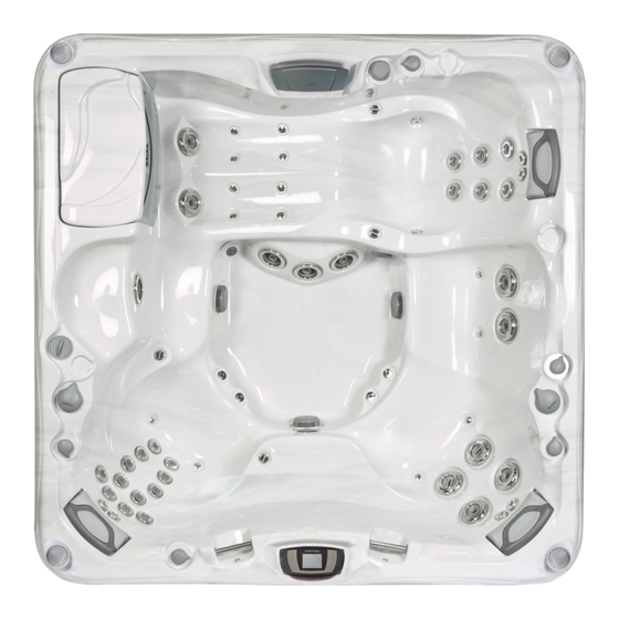
- Page 32 Figure - K (Altamar Hot Tub Features) Control Panel Suction Fitting/Filter Are Located Under Handrail The Filter Lid. The Suction Fitting Light Requires Periodic Cleaning for Optimum Pillows (3 ea.) Performance). Fluidix Euro Jets (4 ea.) AquaTerrace Waterfall Control Valve Fluidix ST Jets (12 ea.)
- Page 33 Figure - L (Marin Hot Tub Features) Select Cycle Mode Display Control Panel Suction Fitting/Filter Are Located Under Handrail The Filter Lid. The Suction Fitting Light Requires Periodic Cleaning for Optimum Pillows (3 ea.) Performance). Fluidix Euro Jets (4 ea.) AquaTerrace Waterfall Control Valve Fluidix ST Jets (10 ea.) AquaTerrace Waterfall Filtration Return...
- Page 34 Figure - M (Capri Hot Tub Features) Control Panel Suction Fitting/Filter Are Located Under Integral Handrail The Filter Lid. The Suction Fitting Gravity Drain Requires Periodic Cleaning for Optimum Pillows (3 ea.) Performance). Fluidix Euro Jets (2 ea.) AquaTerrace Waterfall Fluidix ST Jets (10 ea.) SunScents Dispenser Air Controls (3 ea.)
-
Page 35: Operating Instructions
10.0 Operating Instructions Your Sundance® hot tub has a touch-sensitive control panel, massage selector valves and air control knobs located on the top rim of the hot tub (Figures G-M, page 22-28). These controls let you operate many of the special functions of your Sundance®... -
Page 36: Air Injection
on the footwell and waterfall lights. In random mode, press a second time to freeze random color or continue pressing for one of 7 constant colors. If you go past your favorite color, simply continue pressing to restart the color selection sequence. Note: your color selection is stored in memory and will automatically recall when is the light is cycled on and off. -
Page 37: Selecting The Desired Massage Action
10.7 Selecting The Desired Massage Action Your Sundance® hot tub is equipped to allow you to customize the massage action you desire. Each model incorporates a massage selector(s) that allows you to customize the massage and performance by diverting water between various jet systems. Simply turn massage selector to position A (Combo), B, or C to divert water pressure to various jet groups. -
Page 38: Air Controls
10.9 Air Controls Each jet system has its own air control. These controls allow you to regulate the amount of air which is mixed with the water entering through the jets. Clockwise rotation adds more air and counterclockwise rotation reduces air flow. Note: To minimize heat loss, close all air controls when spa is not in use. - Page 39 for audio playback, simply press download on each enclosure to unlatch it’s “pop-up” mechanism, then release. To retract each speaker before covering hot tub, gently press downward on each enclosure until you feel a slight “click”, then release. Refer to section 22.0 (page 71) for com- plete stereo operation details.
-
Page 40: Maxxus Massage / Waterfall Selector Diagram
10.13 Maxxus Massage / Waterfall Selector Diagram Spa operation subject to change without notice. Page 34... -
Page 41: Maxxus Air Controls Diagram
10.14 Maxxus Air Controls Diagram Spa operation subject to change without notice. Page 35... -
Page 42: Optima Massage / Waterfall Selector Diagram
10.15 Optima Massage / Waterfall Selector Diagram Massage Selectors (1-2): • Massage Selector #1 Controls Pump #1 • Massage Selector #2 Controls Pump #2 Waterfall Selector (2) • Waterfall Selector #3 Controls Waterfall Output. Continously Powered Jets (3): • Jets #4 Are Always on When Pump #1 is Running. •... -
Page 43: Optima Air Controls Diagram
10.16 Optima Air Controls Diagram Spa operation subject to change without notice. Page 37... -
Page 44: Cameo Massage / Waterfall Selector Diagram
10.17 Cameo Massage / Waterfall Selector Diagram Spa operation subject to change without notice. Page 38... -
Page 45: Cameo Air Controls Diagram
10.18 Cameo Air Controls Diagram Spa operation subject to change without notice. Page 39... -
Page 46: Majesta Massage / Waterfall Selector Diagram
10.19 Majesta Massage / Waterfall Selector Diagram Massage Selector Operation Rotate Massage Selector 1 to Divert Water Between Designate Jet Groups. Massage Selector (1): • Massage Selector #1 Controls Pump #1 Waterfall Selector (2) • Waterfall Selector #2 Controls Waterfall Output. Continously Powered Jets (3): •... -
Page 47: Majesta Air Controls Diagram
10.20 Majesta Air Controls Diagram Air Control Operation Rotate Air Controls 1-5 to Add Air to Designated Jet Groups. Spa operation subject to change without notice. Page 41... -
Page 48: Altamar Massage / Waterfall Selector Diagram
10.21 Altamar Massage / Waterfall Selector Diagram Spa operation subject to change without notice. Page 42... -
Page 49: Altamar Air Controls Diagram
10.22 Altamar Air Controls Diagram Spa operation subject to change without notice. Page 43... -
Page 50: Marin Massage / Waterfall Selector Diagram
10.23 Marin Massage / Waterfall Selector Diagram Massage Selector Operation Rotate Massage Selector 1 to Divert Water Between Designated Jet Groups. Select Cycle Mode Display Massage Selector (1): • Massage Selector #1 Controls Pump #1. Waterfall Selector (2): • Waterfall Selector #2 Controls Waterfall. Continuously Powered Jets: All Unmarked Jets Are Always On When Pump #2 is Running. -
Page 51: Marin Air Controls Diagram
10.24 Marin Air Controls Diagram Air Control Operation Rotate Air Controls 1-5 to Add Air to Designated Jet Groups. Select Cycle Mode Display Spa operation subject to change without notice. Page 45... -
Page 52: Capri Massage / Waterfall Selector Diagram
10.25 Capri Massage / Waterfall Selector Diagram Spa operation subject to change without notice. Page 46... -
Page 53: Capri Air Controls Diagram
10.26 Capri Air Controls Diagram Spa operation subject to change without notice. Page 47... -
Page 54: Heating Modes
11.0 Heating Modes The control system in your hot tub activates a programmable “standard” or “economy” mode which effects when the heater operates. Refer to sections 11.1 and 11.2 below for additional information. 11.1 Standard Mode (Factory Default) Standard mode is typically selected by customers in cold climates where heat up times are extended due to lower ambient temperatures. -
Page 55: Programming Instructions
12.0 Programming Instructions 12.1 Programming Filter/Circulation Pump Run Time The Sentry control system allows you to easily adjust two separate as- pects of filter/circulation pump operation: 1. The time of day (start time) the filter/circulation pump turns on. 2. The length of time (duration) the filter/circulation pump operates. The factory default start time is 12:00am (midnight). - Page 56 when “Economy” mode is selected (sec. 11.3), the heater activates only during a programmed filter cycle. When in a Summer Logic condition is active (see note below), the filter/ circulation pump will turn on for all programmed filter cycles. Summer Logic: In warm weather, the water temperature in the hot tub may exceed the set temperature.
-
Page 57: Adjusting Time Of Day
(DOWN) button to adjust the duration in increments of 15 min- utes. 4. Press (DISPLAY) button to save changes and recall the main water temperature display. Note: If no button is pressed within 30 seconds, all changes are recorded and the screen automatically returns to the standard water temperature display. -
Page 58: Locking Filter Cycles
With the panel locked, none of the components can be turned on and the only settings that can be adjusted are the standard and economy filter/heating mode and time of day. All automatic hot tub functions will operate normally. • To Unlock Main Control Panel: Press (DISPLAY) (MODE) and (DOWN) - Page 59 Plus filter cartridge is designed as a disposable cartridge and should be replaced (thrown-out) every 6 months to ensure optimum water filtration. The “Change Filter” reminder icon must be reset at each filter inspection/ replacement interval. It offers a selectable range from 10-120 days or can be disabled (turned off).
-
Page 60: Hot Tub Maintenance
13.0 Hot Tub Maintenance Proper and regular maintenance of your hot tub will Normal Filter Shapes Normal Filter Shapes help it retain its beauty and performance. Your autho- Filter/Circulation Filter/Circulation rized Sundance Dealer can supply you with all the Pump On Pump On information, supplies, and accessory products you will need to accomplish this. -
Page 61: Draining And Refilling
TURN POWER TO HOT TUB OFF! Replace MicroClean Plus Filter cartridge every 6 months, DO NOT Reuse for any reason! Loosen filter nut (A) to provide clearance, Replace (throw-away) the MicroClean filter cartridge then remove used MicroClean Plus filter every 6 months, or as needed! DO NOT reuse this cartridge (steps B-C). -
Page 62: Cleaning The Hot Tub Interior
CAUTION! READ THIS BEFORE DRAINING: To prevent damage to the hot tub’s components, turn off power to the hot tub at the circuit breaker before draining it. Do not turn the power back on until your hot tub has been refilled. There are certain precautions to keep in mind when drain- ing your hot tub. -
Page 63: Pillow Care
13.4 Pillow Care Remove and clean the headrest pillows as needed with soapy water us- ing a cloth or soft-bristle brush. To maintain water resistance and luster, apply a quality vinyl conditioner once a month. IMPORTANT: Never attempt to remove the pillows by pulling on them! The pillows utilize a bolt-on design that prohibits removal without tools. -
Page 64: Winterizing
13.7 Winterizing Your Sundance hot tub is designed to automatically protect itself against freezing when operating properly. During periods of severe freezing temperatures, you should check periodically to be certain that the electri- cal supply to the hot tub has not been interrupted. In extreme, bitter cold weather (less than -20°F) verify the filter/circulation pump is set for 24-hour operation (sec. -
Page 65: Restarting Your Hot Tub In Cold Weather
13.8 Restarting Your Hot Tub in Cold Weather If you want to start up your hot tub after it has sat empty for a time in freezing temperatures, be aware that the water remaining in certain sections of the piping may still be frozen. This situation will block water flow preventing the hot tub from operating properly and possibly damag- ing the equipment. -
Page 66: Other Additives
with the Brominator™, a special compartment built into the floating skim- mer gate to hold bromine tablets. By regulating the number of bromine tablets in the Brominator™ you can control the amount of bromine which is actively working in your hot tub water. A romine residual of 2.0-4.0 ppm is generally considered desirable. -
Page 67: Troubleshooting - Display Messages
If your stainless handrails shows signs of rusting you should: • Wash with fresh water (a good detergent won’t hurt). • Clean with a good car chrome polish. • Wax with an automotive or fiberglass wax. You should never: • Clean with chlorinated cleaners or scouring powders. - Page 68 * NOTE: THIS MESSAGE CAN ALSO APPEAR IF THE PUMP HAS NOT REGAINED PRIME AFTER THE HOT TUB HAS BEEN DRAINED AND REFILLED. IF YOU SUSPECT THAT THIS IS THE CASE, SEE THE INSTRUCTIONS ON PAGE 63 UNDER “PUMP DOES NOT OPERATE AND ICON DOES.”...
-
Page 69: Troubleshooting - Procedures
OPEN OR SHORTED SENSOR (heater disabled) The main temperature sensor is non-functional. This must be repaired only by an authorized dealer or qualified service technician. CLOSED OR SHORTED FLOW SWITCH ON SYSTEM STARTUP (system disabled) Flow switch is non-functional. This must be repaired only by an authorized dealer or qualified service technician. - Page 70 Pump Priming Instructions: Turn off power to the hot tub. Remove the handle from the massage selector supplied by the pump you are priming. Loosen the massage selector’s cap slightly (counterclockwise), listening for the air to seep out. Tighten the cap finger-tight, replace the handle and turn the hot tub’s power back on.
- Page 71 tub to reset. 3. Hot tub water is warmer than 95°F (35°C) and two degrees warmer than the set temperature. The “Summer Logic” safety feature has activated. See note on page 50 for details. Normal Filter Shapes Normal Filter Shapes FILTER CARTRIDGE Your new hot tub is equipped Filter/Circulation...
-
Page 72: Us/Canada 60Hz Maxxus Electrical Wiring Diagram
17.0 US/Canada 60Hz Maxxus Electrical Wiring Diagram Page 66... -
Page 73: Us/Canada 60Hz Altamar/Cameo/Capri/Majesta/Optima/Marin Electrical Wiring Diagram
18.0 US/Canada 60Hz Altamar/Cameo/Capri/Majesta/Optima/ Marin Electrical Wiring Diagram Page 67... -
Page 74: Export 50Hz Maxxus Electrical Wiring Diagram
19.0 Export 50Hz Maxxus Electrical Wiring Diagram Page 68... -
Page 75: Circuit Board Pin Assignments
20.0 Circuit Board Pin Assignments CAUTION: Always remove power to JP20 850 LCD spa before making REVX.XX JP19 JP20 circuit board JP19 changes. Refer to pages 13 & 14 for additional jumper configuration details. JP20-1 Not Used JP19-1 On = ºC Off = ºF JP19-3 Not Used... -
Page 76: Typical Hot Tub Wiring Diagrams A-B
21.0 Typical Hot Tub Wiring Diagrams A-B (US/Canada 60 Hz Models Only) 2-Pole Circuit Breaker with 2-Wire Grounded Load Connection (3 Wires to Hot Tub, 2-Hot (L1-L2), 1-Ground) 240 VAC White (N) Black (L1) 2-Pole GFCI Red (L2) Breaker Red (L2) Main Black (L1) Service... -
Page 77: Optional Sunsound ™ Stereo Receiver Features
™ 22.0 Optional SunSound Stereo Receiver Features 22.1 SunSound Stereo Receiver Button Controls M A R I N E MRD 60 SOURCE LOCAL DISC IN TRACK SCAN POWER TUNE INTRO RANDOM REPEAT DISK BAND MUTE AUDIO AUTO 17 16 15 14 13 11. -
Page 78: Sunsound Stereo Receiver Operation
as follows: Tuner - CD - Tuner. If a source is unavailable (e.g. no CD inserted), that source will not appear on the display. Adjusting Bass Level Press audio button (20) until display reads “BAS.” Rotate volume knob to desired setting. A display of “C O” indicates center, -2 to -12 indi- cates bass cut, and +2 to +12 indicates bass boost. - Page 79 D. Open/Close Front Panel Place thumb on front panel release button (7) with forefinger below front overhang. Press firmly on release button, then flip panel open by pulling outward at top edge. To close panel, flip panel up and press firmly until you hear an audible click.
-
Page 80: Sunsound Stereo Receiver Troubleshooting
frequency with additional button presses. Note: After 3 seconds, seek mode is re-enabled. H. Scan Functions Select any AM or FM band and press scan button (11) to listen to a few seconds of each radio station. The display will flash and the radio will automatically scan to the next higher station, play that station for a few seconds, then scan to the next higher station. -
Page 81: Sunsound Stereo Receiver Cd Player Operation
B. Fogged CDs and Lens This condition may occur when it’s cold. Wipe fogged CDs with a soft cloth. Fogged optical components inside the unit will return to normal operation after an hour in a heated environment. 22.5 SunSound Stereo Receiver CD Player Operation A. -
Page 82: Stereo Receiver Specifications
• Repeat Mode: press the repeat button (18) to repeat the current CD track continuously. The left side of the display reads “RPT” when repeat mode is enabled. 22.6 Stereo Receiver Specifications FM usable sensitivity ........10 dBf FM 50 dB quieting sensitivity. -
Page 83: Standard Wireless Remote Control Functions
22.7 Standard Wireless Remote Control Functions This remote is included with the optional SunSound Stereo system. The jets, lights and air blower buttons on this remote require an optional ISC adapter kit for operation, #20230-001*. Contact your Sundance dealer for details. LIGHT •... - Page 84 Optional ISC Adapter kit Needed for These Button Functions, Part # 20230-001 Light Button: Controls light inten- Jets 1 Button: Turns Jets pump 1 sity: High - Med - Low On and Off LIGHT Air Button: Turns the Blower on Jets 2 &...
-
Page 85: Wireless Remote Battery Replacement Procedure
22.8 Wireless Remote Battery Replacement Procedure Fig. A 1. Start by removing the rubber cover to the remote (Figure A). LIGHT JETS Fig. B 105358 www.polyplanar.com 2. Turn the remote unit over and locate the battery Poly-Planar Inc. Warminster, PA 18974 (215) 675-7805 Made in China OPEN... -
Page 86: Ipod Docking Station
22.9 iPod Docking Station A. Docking Your iPod The Docking Station for iPod is compatible with all dockable Apple iPod models. To install Apple iPod: 1. Locate and open Docking Station door by gently pulling outward on handle as shown (A). -
Page 87: Generic Mp3 Player Operation
C. Use Wireless Remote or Stereo to Operate iPod Button Operation Press Next Track Fast Forward Press & Hold Press Return to Beginning of Current Track Press Recall Previous Tracks Pause (Press Again to resume Play) Press 22.10 Generic MP3 Player Operation A. - Page 88 The following UL requirements must be observed for all spas with optional stereo components installed. “CAUTION - Risk of Electric Shock. Do not leave compartment door open”; “CAUTION - Risk of Electric Shock. Replace components only with identical components”; and Do not operate the audio/video controls while inside the spa.”...
- Page 89 Notes:...
Need help?
Do you have a question about the Altamar and is the answer not in the manual?
Questions and answers