
Subscribe to Our Youtube Channel
Related Manuals for Magnetek Enrange CAN-6


Summary of Contents for Magnetek Enrange CAN-6
- Page 1 CAN-6 Enrange CAN-6 Radio Receiver September 2011 Part Number: 198-00244-1000-R1 ©Copyright 2011 Magnetek Material Handling...
- Page 2 Your New Radio Receiver Thank you for your purchase of Magnetek’s Enrange CAN-6 Radio Controller. Magnetek has set a whole new standard in wireless control performance, dependability, and value with this unique line of Radio Controllers. If your product ever needs modification or service, please contact one of our representatives at the following locations: U.S.
-
Page 3: Table Of Contents
Signal Strength/Error Code LED (Bottom LED on CAN-6 Faceplate) ..... 21 TROUBLESHOOTING ......................22 TROUBLESHOOTING TABLE ..................22 ASSEMBLY AND REPLACEMENT PARTS ..............24 Enrange CAN-6 Instruction Manual September 2011 Page 2 of 24... -
Page 4: Introduction
Magnetek Products to know, understand and follow all of these requirements. It is the responsibility of the owner of the Magnetek Products to make its employees aware of all of the above listed requirements and to make certain that all operators are properly trained. No one should use Magnetek Products prior to becoming familiar with and being trained in these requirements. -
Page 5: Warnings And Cautions
The following information is intended to be used in conjunction with other rules or regulations already in existence. It is important to read all of the safety information contained in this section before installing or operating the Radio Control System. Enrange CAN-6 Instruction Manual September 2011 Page 4 of 24... -
Page 6: Critical Installation Considerations
Enrange CAN-6 Instruction Manual September 2011 Page 5 of 24... -
Page 7: Safety Information & Recommended Training For Radio Controlled Equipment Operators
operate a crane, hoist or lifting device when the device is not centered over the load Enrange CAN-6 Instruction Manual September 2011 Page 6 of 24... -
Page 8: Pre-Operation Test
SHOULD IMMEDIATELY BE TAKEN OUT OF SERVICE AND BE REPORTED TO THE SUPERVISOR. DAMAGED AND INOPERABLE RADIO CONTROLLER EQUIPMENT SHOULD BE RETURNED TO MAGNETEK FOR EVALUATION AND REPAIR. FAILURE TO FOLLOW THIS WARNING COULD RESULT IN SERIOUS INJURY OR DEATH AND DAMAGE TO EQUIPMENT. -
Page 9: Can-6 Receiver Installation
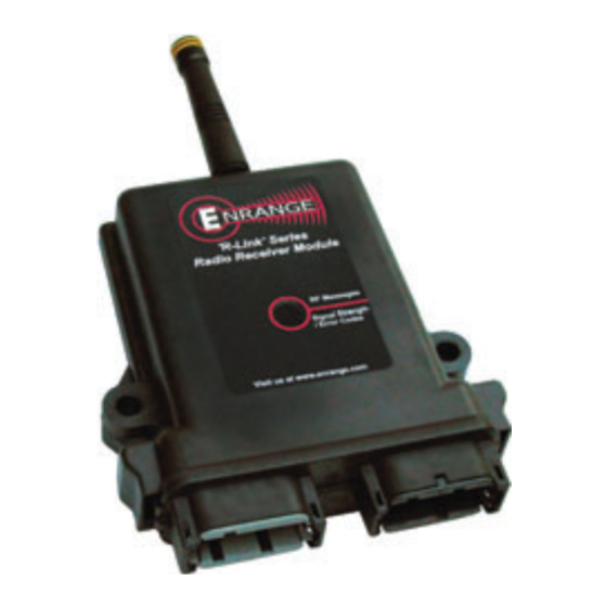
4. Make sure the power to the receiver is the correct DC voltage. 5. Disconnect equipment power prior to system installation. MECHANICAL DRAWINGS Figure 01: Remote Antenna (marked in red) Enrange CAN-6 Instruction Manual September 2011 Page 8 of 24... - Page 10 Figure 02: CAN-6 with external antenna (red) Figure 03: CAN-6 (900 MHz version only) with internal antenna (red) Figure 04: CAN-6 with Con1 and Con2 connectors Figure 05: CAN-6 Side View Enrange CAN-6 Instruction Manual September 2011 Page 9 of 24...
-
Page 11: Installation
The supply power to the CAN-6 system must have a master disconnect and should be fused. NOTE: Magnetek strongly recommends the use of external fuses and circuit disconnects for all CAN-6 Receivers. Consult factory for more information. REMOVAL OF CAN-6 FROM HOUSING Rarely, it might be necessary to access the internal circuit board on the receiver to adjust settings or change the radio channel. -
Page 12: Pin Out Diagram And Definitions
PIN OUT DIAGRAM AND DEFINITIONS Figure 06: Pin out diagram Enrange CAN-6 Instruction Manual September 2011 Page 11 of 24... - Page 13 CAN-bus, external termination is required. Analog Outputs (Right Pins 2–6, 9–12) The right connector has 8 pins for analog outputs. These outputs deliver a voltage from 0 to 10 VDC. Enrange CAN-6 Instruction Manual September 2011 Page 12 of 24...
-
Page 14: Can-6 Receiver Block Diagram
NOTE: Connections are labeled by which side the connector is on the CAN-6 receiver. i.e. L1 is pin 1 on the left connector, R1 is pin 1 on the right connector, etc. Enrange CAN-6 Instruction Manual September 2011 Page 13 of 24... -
Page 15: Configuring The Can-6
The Bank 1 dip switches 1 through 7 are programmed at the factory for custom setting adjustments. Examples of settings that can be utilized are A, B, Both, RF Power, CAN Message Types, etc. Enrange CAN-6 Instruction Manual September 2011 Page 14 of 24... -
Page 16: Receiver Channel Configuration Settings (Dip Switch Bank 2)
(Sections 4.3.1 through 4.3.3) show the channels or protocols available for each radio frequency option of the CAN-6. NOTE: See Section 3.4 for instructions on how to remove the CAN-6 module from the module housing. Enrange CAN-6 Instruction Manual September 2011 Page 15 of 24... -
Page 17: Channel Dip Switch Settings For 900Mhz Part 15
4.3.1 Channel Dip Switch Settings for 900MHz Part 15 Enrange CAN-6 Instruction Manual September 2011 Page 16 of 24... -
Page 18: Channel Dip Switch Settings For 433Mhz Part 15
4.3.2 Channel Dip Switch Settings for 433MHz Part 15 Enrange CAN-6 Instruction Manual September 2011 Page 17 of 24... -
Page 19: Channel Dip Switch Settings For 2.4Ghz @ 50Mw And 125Mw
4.3.3 Channel Dip Switch Settings for 2.4GHz @ 50mW and 125mW Enrange CAN-6 Instruction Manual September 2011 Page 18 of 24... -
Page 20: Fcc Statements
Warning (Part 15.21) Changes or modifications not expressly approved by the party responsible for compliance should void the user’s authority to operate the equipment. Enrange CAN-6 Instruction Manual September 2011 Page 19 of 24... -
Page 21: Normal Operation
Green Slow Blinks - Transmitter is offline (watchdog indicator) Green Fast Blinks - Each blink is a valid RF message Red Blinks - Internal boot-up sequence Red Solid - Error occurred, refer to Error Code LED's blink code Enrange CAN-6 Instruction Manual September 2011 Page 20 of 24... -
Page 22: Signal Strength/Error Code Led (Bottom Led On Can-6 Faceplate)
This can occur when the transmitter powers down from inactivity or goes out of range. The START toggle on the transmitter must be toggled to bring the transmitter back online with the receiver. Enrange CAN-6 Instruction Manual September 2011 Page 21 of 24... -
Page 23: Troubleshooting
(120 Ohms at each end of the bus). receiver value Ensure the correct baud rate is set by all Incorrect baud rate devices on the bus. Enrange CAN-6 Instruction Manual September 2011 Page 22 of 24... - Page 24 Check all wires for loose or damaged Faulty Wiring Outputs not connections. functioning Check all wires and connections for Output is shorted or opened damaged insulation. Table 1: Troubleshooting Table Enrange CAN-6 Instruction Manual September 2011 Page 23 of 24...
-
Page 25: Assembly And Replacement Parts
ASSEMBLY AND REPLACEMENT PARTS If your receiver ever needs repair, we always recommend that you have Magnetek perform the repair. If you need to refer to a parts list, refer to your receiver’s drawing that was included in the shipment of your receiver. Please contact Magnetek’s service department at 1.866.MAG.SERV for information regarding parts and service.
Need help?
Do you have a question about the Enrange CAN-6 and is the answer not in the manual?
Questions and answers