
Subscribe to Our Youtube Channel
Related Manuals for Magnetek Flex M


Summary of Contents for Magnetek Flex M
- Page 1 Flex M RECEIVER Engineered Modular Receiver Part Number: 198-80104-1100 R05 May 2019 © 2019 Magnetek...
- Page 2 SERVICE INFORMATION Your New Radio Remote Control System Thank you for your purchase of Magnetek’s Flex M Receiver Radio Remote Equipment Control. Magnetek has set a whole new standard in radio-remote performance, dependability, and value with this line of modular receivers.
-
Page 3: Table Of Contents
GEN 1 RF/CPU CHANNEL DIP SWITCH SETTINGS ..............39 CHANNEL SETS ..........................44 433MHz CHANNEL SET ......................44 419MHz CHANNEL SET ......................45 2.4 GHz: FHSS..........................46 TROUBLESHOOTING ........................47 Flex M Engineered Receiver Instruction Manual May 2019 Page 3 of 50... - Page 4 TROUBLESHOOTING TABLE ....................48 EU DECLARATION OF CONFORMITY ..................50 Flex M Engineered Receiver Instruction Manual May 2019 Page 4 of 50...
-
Page 5: Product Manual Safety Information
Magnetek Products to know, understand and follow all of these requirements. It is the responsibility of the owner of the Magnetek Products to make its employees aware of all of the above listed requirements and to make certain that all operators are properly trained. No one should use Magnetek Products prior to becoming familiar with and being trained in these requirements. - Page 6 It is important to read all of the safety information contained in this section before installing or operating the Radio Control System. Flex M Engineered Receiver Instruction Manual May 2019 Page 6 of 50...
-
Page 7: Critical Installation Considerations
Flex M Engineered Receiver Instruction Manual May 2019... -
Page 8: Safety Information & Recommended Training For Operators
Operate a crane, hoist, or lifting device when the device is not centered over the load • Operate a crane, hoist, or lifting device if the chain or wire rope is not seated properly in the sprockets, drum or sheave Flex M Engineered Receiver Instruction Manual May 2019 Page 8 of 50... -
Page 9: Pre-Operation Test
PERFORMANCE OR SAFETY CONCERNS ARE OBSERVED, THE EQUIPMENT SHOULD IMMEDIATELY BE TAKEN OUT OF SERVICE AND BE REPORTED TO THE SUPERVISOR. DAMAGED AND INOPERABLE RADIO CONTROLLER EQUIPMENT SHOULD BE RETURNED TO MAGNETEK FOR EVALUATION AND REPAIR. FAILURE TO FOLLOW THIS WARNING COULD RESULT IN SERIOUS INJURY OR DEATH AND DAMAGE TO EQUIPMENT. -
Page 10: Flex M Installation
“dead” spot directly under the antenna. The antenna should be mounted at a 45-degree angle in relation to the operator. Always try to avoid power sources, motors, drives, brakes, etc., when installing the antenna. If necessary, Magnetek offers an external antenna kit. Flex M Engineered Receiver Instruction Manual... -
Page 11: Line Input Considerations
8. Remove excess metal screws, metal filings, and wire clippings from inside of unit. 9. Inspect to make sure no exposed wire has contact with any other wiring or terminals. 10. RC type suppressors are strongly recommended on all contactors. Flex M Engineered Receiver Instruction Manual May 2019 Page 11 of 50... -
Page 12: Receiver Unit Enclosure Mounting
Consult the factory for more information regarding your application. 7. The power source to the Flex M system must have a master disconnect and should be fused. 8. It should not be necessary to set the Access Code or channel, as they are preset. If special field programming is needed, power the unit up on the bench and program the unit for any special configurations or other parameters (see Section 5 for details). -
Page 13: Removal
14. If there are any problems, refer to Section 9. REMOVAL 1. To remove modules from the rail for service, first ensure all power to the Flex M modules has been turned off and proper lockout/tagout procedures have been followed. -
Page 14: Mechanical Drawings
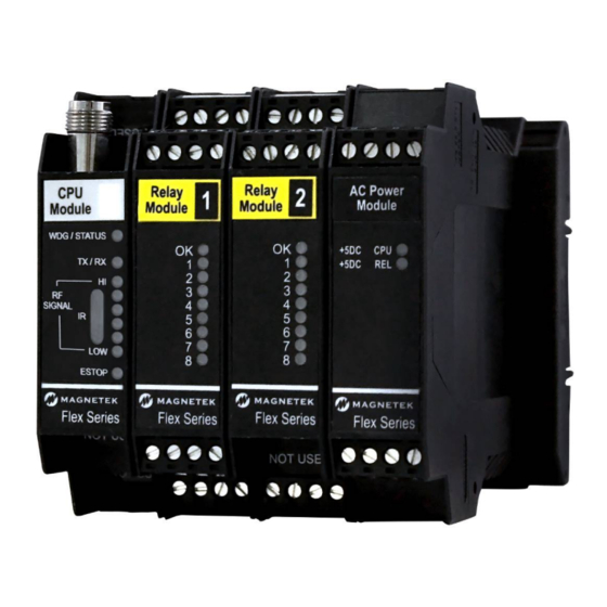
3.10 MECHANICAL DRAWINGS Figure 3. Example Flex M Mechanical Layout Flex M Engineered Receiver Instruction Manual May 2019 Page 14 of 50... -
Page 15: Flex M Modules
Be sure to reference the correct part number for each module type as some of the modules have different versions. NOTE: It is possible that different generations of Flex M modules will be intermixed. While they are meant to be drop-in replacements, some wiring updates may be needed. Refer to the sections below for more information. - Page 16 RF/CPU module aside from either an antenna or a coaxial cable on the TNC antenna connection. For channel dip switch settings for each of the different RF types, refer to the appropriate table in Section Flex M Engineered Receiver Instruction Manual May 2019...
-
Page 17: Rf/Cpu Led Operation
4.1.1 RF/CPU LED OPERATION When the Flex M system supplies power to the RF/CPU module, there is a series of LEDs that indicate the RF/CPU module’s status. Figure 6. GEN1 RF/CPU Module LED Placement • WDG/ONLINE LED: Solid indicates RF communication with transmitter... -
Page 18: Rf/Cpu Module - Gen 2
The external CAN bus is not intended to be used for communication outside of the receiver system. This is intended for future expansion of the Flex M platform. For CAN bus communication outside of the Flex M receiver system, a communication module will need to be used within the system. Jumper J1 is used to indicate if the CAN bus termination resistor is used or not. -
Page 19: Rf/Cpu Led Operation
Figure 8. GEN2 RF/CPU Module Wiring 4.2.1 RF/CPU LED OPERATION When the Flex M system supplies power to the RF/CPU module, there is a series of LEDs that indicate the RF/CPU module’s status. Figure 9. GEN2 RF/CPU Module LED Placement •... -
Page 20: Power Supply Module - Gen 1
The LED overlay decal will be black The Flex M power supply module converts the supply power to 5VDC power for all the attached Flex M modules. This power module has a maximum output supply current of 1000mA. There is one power supply module in the Flex M system. -
Page 21: Power Supply Led Operation
If additional supply current is required, contact the factory for a custom solution. 4.3.1 POWER SUPPLY LED OPERATION When the Flex M system has power supplied, the two LEDs on the power supply module should be lit and solid. Figure 13. GEN1 Power Supply Module LED Placement •... - Page 22 Figure 16. GEN2 Power Supply VDC Wiring NOTES: 1. Although the power module has built-in protection, Magnetek strongly recommends the use of external fuses and circuit disconnects for all Flex modules. 2. The built-in fuse is user serviceable and can be replaced if blown. To check the fuse, remove the power module from the din rail as described in Section 3.9.
-
Page 23: Power Supply Led Operation
4.4.1 POWER SUPPLY LED OPERATION When the Flex M system has power supplied, the two LEDs on the power supply module should be lit and solid. Figure 17. GEN2 Power Supply Module LED Placement +5VDC CPU • Indicates that +5VDC power is going to the CPU •... - Page 24 Figure 18. GEN1 Relay Module Detail View Figure 19. GEN1 Relay Module Wiring Flex M Engineered Receiver Instruction Manual May 2019 Page 24 of 50...
-
Page 25: Relay Module Led Operation
4.5.1 RELAY MODULE LED OPERATION When the Flex M system is supplying power to the Relay module, an LED indicates the power and communication status of the Relay module. Figure 20. GEN1 Relay Module LED Placement • OK LED Solid indicates module communication with system is good 3 Blinks indicates read/write error to attached CPU module Additionally, there are eight LEDs labeled 1 through 8 on the Relay module. - Page 26 Figure 21. GEN2 Relay Module Detail View Figure 22. GEN2 Relay Module Wiring Flex M Engineered Receiver Instruction Manual May 2019 Page 26 of 50...
-
Page 27: Relay Module Led Operation
4.6.1 RELAY MODULE LED OPERATION When the Flex M system is supplying power to the Relay module, an LED indicates the power and communication status of the Relay module. Figure 23. GEN2 Relay Module LED Placement • OK LED Solid indicates module communication with system is good 3 Blinks indicates read/write error to attached CPU module Additionally, there are eight LEDs labeled 1 through 8 on the Relay module. - Page 28 Figure 24. Serial Communications Module Detail View Figure 25. Serial Communications Module Wiring Flex M Engineered Receiver Instruction Manual May 2019 Page 28 of 50...
-
Page 29: Serial Communication Module Led Operation
4.7.1 SERIAL COMMUNICATION MODULE LED OPERATION When the Flex M system is supplying power to the Serial Communication module, an LED indicates the power and communication status of the Serial Communication module. Figure 26. Serial Communications Module LED Placement •... - Page 30 The four analog input signals are able to receive voltage signals from 0 to +10VDC, at an 8-bit resolution. The input impedance is 20K for these inputs. The inputs share a common ground reference, which is shared with the Flex M system ground. Figure 27. Analog I/O Module Detail View Figure 28.
-
Page 31: Analog I/O Module Led Operation
4.8.1 ANALOG I/O MODULE LED OPERATION When the Flex M system is supplying power to the Analog I/O module, an LED indicates the power and communication status of the Analog I/O module. Figure 29. Analog I/O Module LED Placement •... -
Page 32: Digital Input Module - Gen 1
The LED overlay decal will be black The Flex M Digital Input module allows the reading of twelve digital signals (12-24VDC or 50-75VDC). Custom DC voltage inputs are available upon request. The DC power is not supplied by the card, so a separate power supply needs to be installed to the power inputs. -
Page 33: Digital Input Module Led Operation
4.9.1 DIGITAL INPUT MODULE LED OPERATION When the Flex M system is supplying power to the Digital Input module, an LED indicates the power and communication status of the Relay module. Figure 32. GEN1 Digital Input Module LED Placement •... -
Page 34: Digital Input Module - Gen 2
The LED overlay decal will be blue The Flex M Digital Input module allows the reading of eight digital signals. Each of the digital inputs can be configured for a range of 4-36VDC (Low Range) or 36V-240VAC/DC (High Range) operation for either AC or DC voltages via a manual jumper connection. -
Page 35: Digital Input Module Led Operation
Figure 34. GEN2 Digital Input Module Wiring 4.10.1 DIGITAL INPUT MODULE LED OPERATION When the Flex M system is supplying power to the Digital Input module, there is an LED that indicates the power and communication status of the Digital Input module. - Page 36 Digital Input 5 is active (non-zero) • LED6 Digital Input 6 is active (non-zero) • LED7 Digital Input 7 is active (non-zero) • LED8 Digital Input 8 is active (non-zero) Flex M Engineered Receiver Instruction Manual May 2019 Page 36 of 50...
-
Page 37: Programming With Rcp
INJURY, OR EVEN DEATH. ALL EQUIPMENT OPERATORS AND/OR PERSONNEL SHOULD BE NOTIFIED OF ANY RADIO DATA VALUE CHANGES THAT MAY AFFECT OPERATION. Refer to the RCP Users Guide (P/N 178-01702-0010) for information on configuring the Flex M with RCP. Flex M Engineered Receiver Instruction Manual... -
Page 38: Receiver Channel Configuration Settings
This portable transmitter with its antenna complies with FCC’s RF exposure limits for general population/uncontrolled exposure. Flex M Engineered Receiver Instruction Manual May 2019 Page 38 of 50... -
Page 39: Gen 1 Rf/Cpu Channel Dip Switch Settings
DOWN 915.80 MHz DOWN 917.40 MHz DOWN DOWN 923.20 MHz DOWN 927.00 MHz DOWN 927.30 MHz Table 1. CHANNEL DIP SWITCH SETTINGS FOR 900MHZ PART 15 RF/CPU MODULE Flex M Engineered Receiver Instruction Manual May 2019 Page 39 of 50... - Page 40 900MHZ @ 200MW RF/CPU MODULE (25-02-074-815E) NOTE: Each channel consists of 50+ frequencies within 902 -928 MHz. During operation, all available frequencies will be used by a "Frequency Hopping" protocol. Flex M Engineered Receiver Instruction Manual May 2019 Page 40 of 50...
- Page 41 434.250 MHz DOWN DOWN 434.300 MHz DOWN DOWN 434.350 DOWN 434.400 DOWN DOWN 434.450 DOWN 434.500 DOWN 434.550 Table 3. CHANNEL DIP SWITCH SETTINGS FOR 433MHZ PART 15 Flex M Engineered Receiver Instruction Manual May 2019 Page 41 of 50...
- Page 42 Table 4. CHANNEL DIP SWITCH SETTINGS FOR 2.4GHZ RF/CPU MODULES NOTE: Each channel consists of 43+ frequencies within the 2.4GHz range. During operation, all available frequencies will be used by a "Frequency Hopping" protocol. Flex M Engineered Receiver Instruction Manual May 2019 Page 42 of 50...
- Page 43 DOWN AKA05 434.125 DOWN DOWN AKA06 434.325 DOWN AKA07 434.525 DOWN DOWN AKA08 434.725 DOWN Table 5. CHANNEL DIP SWITCH SETTINGS FOR 433MHZ (TELEMOTIVE CHANNEL SET) RF/CPU MODULE Flex M Engineered Receiver Instruction Manual May 2019 Page 43 of 50...
-
Page 44: Channel Sets
434.150 MHz 434.200 MHz 434.250 MHz 434.300 MHz 434.350 MHz 434.400 MHz 434.450 MHz 434.500 MHz 434.550 MHz NOTE: Channels marked with * are approved for use in Australia. Flex M Engineered Receiver Instruction Manual May 2019 Page 44 of 50... -
Page 45: 419Mhz Channel Set
417.050 419.600 417.100 419.650 417.150 419.700 417.200 419.750 417.250 419.800 417.300 419.850 417.350 419.900 417.400 419.950 417.450 NOTE: Channels marked with * are approved for use in China. Flex M Engineered Receiver Instruction Manual May 2019 Page 45 of 50... -
Page 46: Ghz: Fhss
This receiver is available with optional licensed frequencies per customer request. If utilizing a licensed frequency, please refer to the factory application documentation that shipped with the receiver, or contact the factory for licensed frequency details. Flex M Engineered Receiver Instruction Manual May 2019 Page 46 of 50... -
Page 47: Troubleshooting
PERFORMANCE OR SAFETY CONCERNS ARE OBSERVED, THE EQUIPMENT SHOULD IMMEDIATELY BE TAKEN OUT OF SERVICE AND BE REPORTED TO THE SUPERVISOR. DAMAGED AND INOPERABLE RADIO CONTROLLER EQUIPMENT SHOULD BE RETURNED TO MAGNETEK FOR EVALUATION AND REPAIR. FAILURE TO FOLLOW THIS WARNING COULD RESULT IN SERIOUS INJURY OR DEATH AND DAMAGE TO EQUIPMENT. -
Page 48: Flex M Engineered Receiver Instruction Manual May
Refer to Section 3.4 for installation. Flex M Engineered Receiver Instruction Manual May 2019 Page 48 of 50... - Page 49 Ensure jumpers for relays K1 and K2 are opposite from allowing active state to have installed in the desired positions. contacts either open or what is expected closed. Flex M Engineered Receiver Instruction Manual May 2019 Page 49 of 50...
-
Page 50: Eu Declaration Of Conformity
10. EU DECLARATION OF CONFORMITY Flex M Engineered Receiver Instruction Manual May 2019 Page 50 of 50...
Need help?
Do you have a question about the Flex M and is the answer not in the manual?
Questions and answers