
Related Manuals for Magnetek FLEX M Series


Summary of Contents for Magnetek FLEX M Series
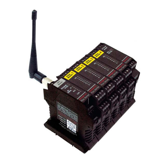
- Page 1 FLEX M Pre-Engineered (Flex M-16, -24, -32) Modular Receiver Part Number: 198-00121 R4 October 2014 © 2014 Magnetek Material Handling...
- Page 2 Sales: +1.262.783.3510 Service: +1.262.783.3508 Magnetek, Inc. has additional satellite locations for Canada and the United States. For more information, please visit http://www.magnetek.com. ©2014 MAGNETEK All rights reserved. This notice applies to all copyrighted materials included with this product, including, but not limited to, this manual and software embodied within the product. This manual is intended for the sole use of the person(s) to whom it was provided, and any unauthorized distribution of the manual or dispersal of its contents is strictly forbidden.
-
Page 3: Table Of Contents
TABLE OF CONTENTS 1.0: CRITICAL INSTALLATION CONSIDERATIONS ..............3 1.1 GENERAL ..........................3 1.2 PERSONS AUTHORIZED TO OPERATE RADIO CONTROLLED EQUIPMENT ....3 1.3 SAFETY INFORMATION & RECOMMENDED TRAINING FOR OPERATORS ....4 1.4 PRE-OPERATION TEST ....................... 5 ... - Page 4 Magnetek Products to know, understand and follow all of these requirements. It is the responsibility of the owner of the Magnetek Products to make its employees aware of all of the above listed requirements and to make certain that all operators are properly trained. No one should use Magnetek Products prior to becoming familiar with and being trained in these requirements.
- Page 5 WARNINGS and CAUTIONS Throughout this document WARNING and CAUTION statements have been deliberately placed to highlight items critical to the protection of personnel and equipment. WARNING – A warning highlights an essential operating or maintenance procedure, practice, etc. which if not strictly observed, could result in injury or death of personnel, or long term physical hazards.
-
Page 6: Critical Installation Considerations
1.0: CRITICAL INSTALLATION CONSIDERATIONS WARNING PRIOR TO INSTALLATION AND OPERATION OF THIS EQUIPMENT, READ AND DEVELOP AN UNDERSTANDING OF THE CONTENTS OF THIS MANUAL AND THE OPERATION MANUAL OF THE EQUIPMENT OR DEVICE TO WHICH THIS EQUIPMENT WILL BE INTERFACED. FAILURE TO FOLLOW THIS WARNING COULD RESULT IN SERIOUS INJURY OR DEATH AND DAMAGE TO EQUIPMENT. -
Page 7: Safety Information & Recommended Training For Operators
1.3 SAFETY INFORMATION & RECOMMENDED TRAINING FOR OPERATORS Anyone being trained to operate radio controlled equipment should possess as a minimum the following knowledge and skills before using the radio controlled equipment. The operator should: have knowledge of hazards pertaining to equipment operation ... -
Page 8: Pre-Operation Test
SHOULD IMMEDIATELY BE TAKEN OUT OF SERVICE AND BE REPORTED TO THE SUPERVISOR. DAMAGED AND INOPERABLE RADIO CONTROLLER EQUIPMENT SHOULD BE RETURNED TO MAGNETEK FOR EVALUATION AND REPAIR. FAILURE TO FOLLOW THIS WARNING COULD RESULT IN SERIOUS INJURY OR DEATH AND DAMAGE TO EQUIPMENT. -
Page 9: Flex M Receiver Installation
2.0 FLEX M RECEIVER INSTALLATION WARNING BEFORE OPERATING THE RECEIVER FAMILIARIZE YOURSELF WITH ALL SAFETY INFORMATION IN THIS MANUAL, APPROPRIATE MANUAL SUPPLEMENTS AND ANY OTHER LOCAL, STATE, OR FEDERAL RULES OR REGULATIONS ALREADY IN EXISTENCE. FAILURE TO FOLLOW THIS WARNING COULD RESULT IN SERIOUS INJURY OR DEATH AND DAMAGE TO EQUIPMENT. 2.1 PRE-INSTALLATION 1. -
Page 10: Mechanical Drawings
2.2 MECHANICAL DRAWINGS TYPICAL MECHANICAL LAYOUTS Figure 1: Mechanical Layout Enrange Flex M Pre-Engineered Modular Receiver Manual October 2014 Page 7 of 31... -
Page 11: Installation
10. Modules MUST be installed so that the RF/CPU module is on the left end of the rail and the power supply module is on the right end of the rail. NOTE: Magnetek strongly recommends the use of external fuses and circuit disconnects for all Flex Modules. Consult factory for more information. -
Page 12: Removal
2.4 REMOVAL 1. To remove modules from the rail for service, first ensure all power to the Flex M modules has been turned off and proper lockout/tagout procedures have been followed. 2. Remove one end rail clamp and un-nest the module that you wish to remove by separating it from the others on the rail. -
Page 13: Normal Operation
3.0 NORMAL OPERATION During the operation of the receiver, following the LED indicators will allow observation of the status of the Flex M receiver. 3.1 POWER SUPPLY MODULE When the Flex M system has power supplied, the two LEDs on the power supply module should be lit and solid. -
Page 14: Flex Module Types
4.0 FLEX MODULE TYPES The Flex M system consists of an RF/CPU module, multiple relay modules and a power supply module. 4.1 FLEX RF/CPU MODULE The Flex RF/CPU Module is the main module that receives radio signals from a paired transmitter and interprets those signals into the appropriate response from the attached I/O modules. -
Page 15: Bank 1 Switch 7 - Auxiliary Relay Output Select (Normally Off)
4.1.1.3 Bank 1 Switch 7 – Auxiliary Relay Output Select (Normally OFF) Definition: This feature is only for custom crane relay configurations that have outputs that can be configured as either A/B select or Aux 1/2. Programming: Turning bank 1 dip switch position 7 OFF (0) sets the outputs to use Aux 1/2 logic. Turning bank 1 dip switch position 7 ON (1) sets the outputs to use A/B select logic. -
Page 16: Bank 2 Switch 3 - Aux 5/6 Output Configuration (Normally On)
4.1.2.3 Bank 2 Switch 3 – AUX 5/6 Output Configuration (Normally ON) Definition: This feature sets the Aux 5/6 output relays to be either momentary or latched. When set for momentary outputs, each output will remain on as long as the corresponding button on the transmitter is held. -
Page 17: Flex M 120Vac Power Module
Relay 8 Relay Output 8 Input Power Relay 7 Relay Output 7 Input Power Relay 6 Input Power Relay Output 6 Relay 5 Input Power Relay Output 5 Relays 1-4 Relay Output 4 Input Power Relay Output 3 Relay Output 2 Relay Output 1 Figure 4: Typical Relay Wiring 4.3 FLEX M 120VAC POWER MODULE... - Page 18 The fuse location is shown in the PCB view above. Use a multimeter to check for continuity across the fuse. If the fuse is blown, contact Magnetek to send the module in for service. 3. The total system Current Consumption should not exceed the Maximum Output Supply Current of 1000mA.
-
Page 19: Flex Systems - Overview, Settings And Wiring Diagrams
5.0 FLEX SYSTEMS – OVERVIEW, SETTINGS AND WIRING DIAGRAMS Magnetek offers the Pre-Engineered Flex M systems with the options for 16, 24, and 32 relay outputs. The following sections describe the overview and wiring diagrams for the Pre-Engineered Flex M systems. -
Page 20: Flex M 16 Relay Configuration Descriptions
5.1.2 Flex M 16 Relay Configuration Descriptions Enrange Flex M Pre-Engineered Modular Receiver Manual October 2014 Page 17 of 31... - Page 21 Enrange Flex M Pre-Engineered Modular Receiver Manual October 2014 Page 18 of 31...
- Page 22 Enrange Flex M Pre-Engineered Modular Receiver Manual October 2014 Page 19 of 31...
- Page 23 Enrange Flex M Pre-Engineered Modular Receiver Manual October 2014 Page 20 of 31...
-
Page 24: Flex M-24 System Overview
5.2 FLEX M-24 SYSTEM OVERVIEW FlexM-24 24 output Flex M system with 120VAC power card, RF/CPU card, and three 8 output relay cards. 5.2.1 Flex M 24 Relay Configuration Settings (Bank 1 on RF/CPU Module) Enrange Flex M Pre-Engineered Modular Receiver Manual October 2014 Page 21 of 31... -
Page 25: Flex M 24 Relay Configuration Descriptions
5.2.2 Flex M 24 Relay Configuration Descriptions Enrange Flex M Pre-Engineered Modular Receiver Manual October 2014 Page 22 of 31... -
Page 26: Flex M-32 System Overview
5.3 FLEX M-32 SYSTEM OVERVIEW FlexM-32 32 output Flex M system with 120VAC power card, RF/CPU card, and four 8 output relay cards. To enable the tandem mode operation in the receiver, dip switch 1-8 needs to be set to the UP position. When tandem mode operation is enabled, the Motion 3 paddle lever will operate both the Main Hoist (Motion 3) output and the Aux Hoist (Motion 4) output when the rotary switch on the transmitter is in the tandem position. -
Page 27: Flex M 32 Relay Configuration Descriptions
5.3.2 Flex M 32 Relay Configuration Descriptions Enrange Flex M Pre-Engineered Modular Receiver Manual October 2014 Page 24 of 31... - Page 28 Enrange Flex M Pre-Engineered Modular Receiver Manual October 2014 Page 25 of 31...
- Page 29 Enrange Flex M Pre-Engineered Modular Receiver Manual October 2014 Page 26 of 31...
-
Page 30: Channel Configuration Settings (Bank 2 On Rf/Cpu Module)
6.0 CHANNEL CONFIGURATION SETTINGS (BANK 2 ON RF/CPU MODULE) NOTE: See Section 2.4 for instructions on how to remove the CPU/RF module from the Din rail and how to remove the PCB from the module housing. 6.1 FCC STATEMENTS Compliance Statement (Part 15.19) This device complies with Part 15 of FCC rules. -
Page 31: Troubleshooting
TAKEN OUT OF SERVICE AND BE REPORTED TO THE SUPERVISOR. DAMAGED AND INOPERABLE RADIO CONTROLLER EQUIPMENT SHOULD BE RETURNED TO MAGNETEK FOR EVALUATION AND REPAIR. FAILURE TO FOLLOW THIS WARNING COULD RESULT IN SERIOUS INJURY OR DEATH AND DAMAGE TO EQUIPMENT. -
Page 32: Troubleshooting Table
7.1 TROUBLESHOOTING TABLE Problems Possible Reasons Suggestions Supplied voltage is out of the Ensure the voltage is 120VAC nominal acceptable range Receiver will not turn on, +5VDC Internal fuse has blown on CPU/RELAY LEDs Contact the factory for repair on Power Supply power supply module Module do not light Internal power supply on... - Page 33 Problems Possible Reasons Suggestions Move the transmitter and receiver closer The transmitter is going in together and out of range (transmitter and receiver are on the edge Relocate the receiver antenna to where it Receiver responds of the transmission range) has a better line of sight with the transmitter to the transmitter Inspect the antenna on the receiver for...
-
Page 34: Assembly And Replacement Parts
7.2 ASSEMBLY AND REPLACEMENT PARTS Description Part Number 900MHz CPU/RF Power Module 25-02-074-800E 120VAC Power Module 25-02-074-804E Relay Module 25-02-074-805E 900MHz Antenna Kit 20-650-0021E Module Replacement Plugs 01-300-0031E Arc Suppressor/Snubbers 20-680-0000E Enrange Flex M Pre-Engineered Modular Receiver Manual October 2014 Page 31 of 31...
Need help?
Do you have a question about the FLEX M Series and is the answer not in the manual?
Questions and answers