
Related Manuals for Magnetek MHR


Summary of Contents for Magnetek MHR
- Page 1 Radio Controller June 2017 Part Number: 195-50488-0100 R7 © 2017 Magnetek Material Handling...
- Page 2 Your New Radio Receiver Thank you for your purchase of Magnetek’s MHR Radio Controller. Magnetek has set a whole new standard in wireless control performance, dependability, and value with this unique new line of Mobile Hydraulic Controllers. If your product ever needs modification or service, please contact one of our representatives at the following locations: U.S.
-
Page 3: Table Of Contents
4.3 NORMAL OPERATING STATUS ..................38 4.4 LED STATUS INDICATION ....................39 4.4.1 STATUS/ERR LED (left LED on MHR faceplate) ............39 4.4.2 PWR/COMM LED (right LED on MHR faceplate) ............39 5.0 OPTIONAL PROGRAMMING WITH RCP ................40 ... - Page 4 Magnetek Products to know, understand and follow all of these requirements. It is the responsibility of the owner of the Magnetek Products to make its employees aware of all of the above listed requirements and to make certain that all operators are properly trained. No one should use Magnetek Products prior to becoming familiar with and being trained in these requirements.
- Page 5 The following information is intended to be used in conjunction with other rules or regulations already in existence. It is important to read all of the safety information contained in this section before installing or operating the Radio Control System. MHR Radio Controller Instruction Manual June 2017 Page 4 of 58...
-
Page 6: Critical Installation Considerations
The operator must exercise extreme caution at all times. Workers must constantly be alert to avoid accidents. The following recommendations have been included to indicate how careful and thoughtful actions may prevent injuries, damage to equipment, or even save a life. MHR Radio Controller Instruction Manual June 2017 Page 5 of 58... -
Page 7: Persons Authorized To Operate Radio Controlled Equipment
Use the crane, hoist or lifting device to lift, support or transport people Lift or carry any loads over people MHR Radio Controller Instruction Manual June 2017 Page 6 of 58... -
Page 8: Pre-Operation Test
SHOULD IMMEDIATELY BE TAKEN OUT OF SERVICE AND BE REPORTED TO THE SUPERVISOR. DAMAGED AND INOPERABLE RADIO CONTROLLER EQUIPMENT SHOULD BE RETURNED TO MAGNETEK FOR EVALUATION AND REPAIR. FAILURE TO FOLLOW THIS WARNING COULD RESULT IN SERIOUS INJURY OR DEATH AND DAMAGE TO EQUIPMENT. - Page 9 THE OPERATOR SHOULD BE PROPERLY QUALIFIED TO OPERATE THE EQUIPMENT WITH MANUAL CONTROLS. FAILURE TO FOLLOW THIS WARNING COULD RESULT IN SERIOUS INJURY OR DEATH AND DAMAGE TO EQUIPMENT. MHR Radio Controller Instruction Manual June 2017 Page 8 of 58...
- Page 10 OPERATED AND ALL INDICATORS ON THE EQUIPMENT AND RADIO CONTROLS CAN BE SEEN. FAILURE TO FOLLOW THIS WARNING COULD RESULT IN SERIOUS INJURY OR DEATH AND DAMAGE TO EQUIPMENT. MHR Radio Controller Instruction Manual June 2017 Page 9 of 58...
- Page 11 OPERATED AND LOAD HAS A SAFE PLACE TO BE SET IN THE EVENT OF STRONG WIND GUSTS. FAILURE TO FOLLOW THIS WARNING COULD RESULT IN SERIOUS INJURY OR DEATH AND DAMAGE TO EQUIPMENT. MHR Radio Controller Instruction Manual June 2017 Page 10 of 58...
-
Page 12: Mhr Receiver Installation
2.0 MHR RECEIVER INSTALLATION WARNING PRIOR TO INSTALLATION AND OPERATION OF THIS EQUIPMENT, MAGNETEK SHOULD BE CONSULTED TO ASSESS THE OVERALL RISKS IN OPERATING THE EQUIPMENT INTERFACED. FAILURE TO FOLLOW THIS WARNING COULD RESULT IN SERIOUS INJURY OR DEATH AND DAMAGE TO EQUIPMENT. -
Page 13: Pre-Installation
3. Make sure that your equipment is working properly in manual mode prior to system installation. 4. Make sure the power to the receiver is the correct DC voltage. 5. Disconnect equipment power prior to system installation. MHR Radio Controller Instruction Manual June 2017 Page 12 of 58... -
Page 14: Mechanical Drawings
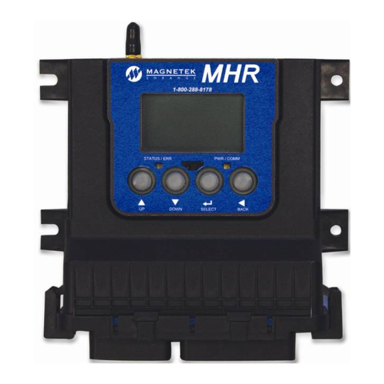
2.2 MECHANICAL DRAWINGS Figure 01: Remote Antenna (marked in red) Figure 02: MHR with external antenna (red) Figure 03: MHR with internal antenna (red) MHR Radio Controller Instruction Manual June 2017 Page 13 of 58... -
Page 15: Installation
Figure 04: MHR with Con1 and Con2 connectors Figure 05: MHR Side View 2.3 INSTALLATION 1. Determine the location of your antenna from Figures 01-03 (antenna is designated with red arrow). Be sure to mount the receiver antenna in direct line-of-sight of the operator and free from all obstructions. -
Page 16: Pin Out And Diagram Definitions
Con2 (30 pos) -Vbattery -V Bat Crimps (14-18 425-00-00- 01-550-0056E -Vbattery -V Bat AWG) 873/PCS 581-00-00- Vbattery +V Bat Sealing plug 20-990-0179E Vbattery +V Bat Vbattery +V Bat MHR Radio Controller Instruction Manual June 2017 Page 15 of 58... - Page 17 The MHR is equipped with a battery backup for the real time clock and calendar. Therefore, power can be completely disconnected from the MHR when not in use. NOTE: The backup battery is internal to the MHR and should only be replaced by the factory. MHR Radio Controller Instruction Manual...
- Page 18 For PWM and digital outputs, the high side of the load is connected to the IO pin and the low side can be tied to a chassis ground (see Figure 09) or to the return pin on the MHR to alleviate the need for an external diode when driving inductive loads (see Figure 08).
- Page 19 Figure 08: MHR driving Current Compensated or PWM load using Return Pin and internal diodes NOTE: This is a simplified schematic. Figure 09: MHR PWM or Digital ON/OFF load using external ground and external diodes NOTE: This is a simplified schematic.
-
Page 20: Mhr Receiver Block Diagram
2.5 MHR RECEIVER BLOCK DIAGRAM NOTE: Connections are labeled by which side the connector is on the MHR receiver, i.e. CON1 is on the left side, CON2 is on the right side. See Figure 6 in Section 2.4 for more detail. - Page 21 MHR Radio Controller Instruction Manual June 2017 Page 20 of 58...
- Page 22 MHR Radio Controller Instruction Manual June 2017 Page 21 of 58...
- Page 23 MHR Radio Controller Instruction Manual June 2017 Page 22 of 58...
-
Page 24: Configuring The Mhr
3.0 CONFIGURING THE MHR The Setup Mode can be used to edit configuration settings so that the MHR can be used in many different scenarios. NOTE: No parameter changes will take effect until the user has selected ‘Save and Exit’ from the Setup Mode. - Page 25 MHR will enter the setup menu. NOTE: If the wrong password is entered, the MHR will go back to its normal operation screen. The procedure to enter setup mode will have to be restarted to get back to the password entry screen.
-
Page 26: Setup Mode Menu
SOFTWARE VERSIONS – displays installed software version numbers • SAVE AND EXIT - Save changes and continue to normal operation • EXIT WITHOUT SAVE – Exit but discard changes MHR Radio Controller Instruction Manual June 2017 Page 25 of 58... -
Page 27: Device Configuration
433MHz system are 1 through 32. The user selectable channels for a 2.4GHz system are 1 through 32. When the RF channel option is selected from the menu, the channels are user selectable by using the buttons. MHR Radio Controller Instruction Manual June 2017 Page 26 of 58... - Page 28 • Password The password is used to restrict access to the configuration menu on the MHR. Having an active password prevents accidental changes to the receiver. NOTE: Familiarize yourself with PASS ENABLE section before entering a password.
- Page 29 • Pass Enable (Enable or disable the password) The password is used to restrict access to the configuration menu on the MHR. Having an active password prevents accidental changes to the receiver. NOTE: Please familiarize yourself with this section before entering a password.
- Page 30 Time • This menu option allows the operator to adjust the time that is stored on the MHR. The time can be adjusted by using the buttons to cycle through each digit. Use the buttons to change the values of the digit selected.
-
Page 31: Io Configuration
When current compensated (closed loop systems) is selected in the output type, the MHR supports 75 to 1000Hz PWM frequencies. • When open loop PWM is selected in the output type, the MHR supports 33 to 1000Hz PWM frequencies. For frequencies used outside of these ranges, please contact the factory. -
Page 32: Individual Output Configuration
Individual Output Configuration: Once an individual output is selected, the following parameters may be changed: • Config Type – This menu option allows the user to set the MHR outputs up for the application in which it is being used. The config type options are: •... - Page 33 After the last digit is entered on the far right side of the PWM Frequency screen, press return to the selected output configuration menu. To exit back to the main menu screen press the button. MHR Radio Controller Instruction Manual June 2017 Page 32 of 58...
-
Page 34: Can Configuration
CAN 1 Baud Rate – This setting enables the operator to select the CAN 1 network communication speed The available Baud Rate options are: • • 125k • 250k • 500k MHR Radio Controller Instruction Manual June 2017 Page 33 of 58... -
Page 35: Project Specific Options
• CAN 1 Source Addr - This is the address that the MHR will use as the source address when transmitting messages on the CAN 1 bus network. • 0 through 255 CAN 1 Identifier Bit - This option allows the operator to select between an 11 bit or 29 bits •... -
Page 36: Software Versions
Temperature Temperature within the unit’s enclosure. 3.8 SOFTWARE VERSIONS This section displays the software versions that are active on the MHR. There are no user selectable options in this menu item. To exit the software version screen, press the button to return to the main setup menu screen. -
Page 37: Normal Operation
EQUIPMENT. FAILURE TO FOLLOW THIS WARNING COULD RESULT IN SERIOUS INJURY OR DEATH AND DAMAGE TO EQUIPMENT. When starting up the MHR in the normal operation mode, the MHR will cycle through a few start- up screens before going to the normal operation screen. -
Page 38: Normal Operating Screen
Transmitter and Receiver Access Code do not match, no communication will occur. NOTE: During initialization of the MHR, both the PWR/COMM and STATUS/ERR LEDs will briefly illuminate. This is a normal function of the initialization process for the MHR. 4.2 NORMAL OPERATING SCREEN... -
Page 39: Normal Operating Status
MHR, but the transmitter has been shut off or gone out of range. This will also show if the MHR was just powered on and no transmitter has been linked yet. -
Page 40: Led Status Indication
4.4 LED STATUS INDICATION The MHR has two LEDs for indicating the MHR status at a glance during normal operation. The left LED indicates the MHR’s status while the right LED indicates power/communication. STATUS/ERR PWR/COMM Indication LED Indication LED 4.4.1 STATUS/ERR LED (left LED on MHR faceplate) -
Page 41: Optional Programming With Rcp
5.0 OPTIONAL PROGRAMMING WITH RCP Using the optional RCP software makes programming of the MHR easier and allows settings to be saved for future reference. WARNING THE USE OF RCP (RADIO CONTROL PROGRAMMER) IS INTENDED FOR USE BY AUTHORIZED PERSONS ONLY. -
Page 42: Connecting The Mhr To A Computer
MHR USB cable can be added by simply plugging in the connector. This option provides a USB- mini B plug for connection to a computer system. If not using the MHR Pre-wired Cable Kit, the MHR can be wired for USB connection using the pin outs in the figure below. -
Page 43: Programming With Rcp
It is designed for communication from your PC to the MHR and other Magnetek radio control products. For more information on how to program the MHR with the RCP, please reference the RCP Users Guide (p/n 178-01702-0010). This guide is available on Magnetek’s website, and can be ordered from a Magnetek Sales Representative. -
Page 44: Channel And Frequency Designations By Count
434.150 MHz 434.200 MHz 434.250 MHz 434.300 MHz 434.350 MHz 434.400 MHz 434.450 MHz 434.500 MHz 434.550 MHz NOTE: Channels marked with * are approved for use in Australia. MHR Radio Controller Instruction Manual June 2017 Page 43 of 58... -
Page 45: 419Mhz Channel Set
419.550 417.050 419.600 417.100 419.650 417.150 419.700 417.200 419.750 417.250 419.800 417.300 419.850 417.350 419.900 417.400 419.950 417.450 NOTE: Channels marked with * are approved for use in China. MHR Radio Controller Instruction Manual June 2017 Page 44 of 58... -
Page 46: Ghz: Fhss
Warning (Part 15.21) Changes or modifications not expressly approved by the party responsible for compliance should void the user’s authority to operate the equipment. MHR Radio Controller Instruction Manual June 2017 Page 45 of 58... -
Page 47: Troubleshooting
CAN-bus. Work with CAN bus your supplier to determine if this is the case. Ensure the correct baud rate is set by all Incorrect baud rate devices on the bus. MHR Radio Controller Instruction Manual June 2017 Page 46 of 58... - Page 48 See Alarm Table below if value is given. operating Check Manufacturer Valve Specs with Incorrect Valve Settings respect to PWM, Duty-Cycle, Voltage. Clock is not Internal Battery is Dead Consult factory. working MHR Radio Controller Instruction Manual June 2017 Page 47 of 58...
-
Page 49: Alarm Table
RF FAIL properly RECALIB The real time clock will not The battery for the be able to keep current Contact the factory for MHR real time clock is not BATTERY time if unit is powered off battery replacement working Another transmitter... - Page 50 9 OC ERR is fixed and power to the The output was shut and power cycle the system system is cycled off to prevent damage to the hardware. MHR Radio Controller Instruction Manual June 2017 Page 49 of 58...
- Page 51 The output was shut and power cycle the system system is cycled off to prevent damage to the hardware. MHR Radio Controller Instruction Manual June 2017 Page 50 of 58...
- Page 52 The is fixed and power to the SHORT cycle the system output was shut off to system is cycled prevent damage to the hardware. MHR Radio Controller Instruction Manual June 2017 Page 51 of 58...
- Page 53 The is fixed and power to the SHORT cycle the system output was shut off to system is cycled prevent damage to the hardware. MHR Radio Controller Instruction Manual June 2017 Page 52 of 58...
- Page 54 The is fixed and power to the SHORT cycle the system output was shut off to system is cycled prevent damage to the hardware. MHR Radio Controller Instruction Manual June 2017 Page 53 of 58...
- Page 55 The is fixed and power to the SHORT cycle the system output was shut off to system is cycled prevent damage to the hardware. MHR Radio Controller Instruction Manual June 2017 Page 54 of 58...
- Page 56 The is fixed and power to the SHORT cycle the system output was shut off to system is cycled prevent damage to the hardware. MHR Radio Controller Instruction Manual June 2017 Page 55 of 58...
- Page 57 The is fixed and power to the SHORT cycle the system output was shut off to system is cycled prevent damage to the hardware. MHR Radio Controller Instruction Manual June 2017 Page 56 of 58...
-
Page 58: Assembly And Replacement Parts
7.3 ASSEMBLY AND REPLACEMENT PARTS If your receiver ever needs repair, we always recommend that you have Magnetek perform the repair. If you need to refer to a parts list, refer to your receiver’s drawing that was included in the shipment of your receiver. -
Page 59: Eu Declaration Of Conformity
8.0 EU DECLARATION OF CONFORMITY MHR Radio Controller Instruction Manual June 2017 Page 58 of 58...
Need help?
Do you have a question about the MHR and is the answer not in the manual?
Questions and answers