
Related Manuals for Jet M-708448


Summary of Contents for Jet M-708448
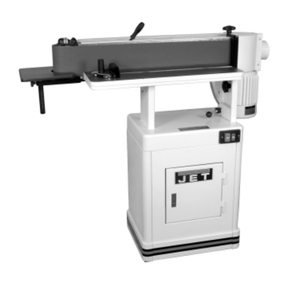
- Page 1 EHVS-80CS Edge Horizontal/Vertical Sander JET EQUIPMENT & TOOLS, INC. A WMH Company www.jettools.com OWNER'S MANUAL P.O. BOX 1349 Auburn, WA 98071-1349 e-mail jet@jettools.com 253-351-6000 Fax 253-939-8001 M-708448 2 / 0 2...
-
Page 2: Warranty And Service
Completely read the safety and maintenance instructions before operating or servicing the machine. To obtain maximum life and efficiency from your sander, and to aid in using the machine safely, read this manual thoroughly and follow instructions carefully. -
Page 3: Warning
1. Read and understand the entire instruction manual before attempting assembly or operation. 2. This sander is designed and intended for use by properly trained and experienced personnel only. If you are not familiar with the proper and safe operation of a sander, do not use until proper training and knowledge have been obtained. -
Page 4: Grounding Instructions
115 Volt Operation As received from the factory, your sander is ready to run at 115 volt operation. This sander, when wired for 115 volt, is intended for use on a circuit that has an outlet and a plug that looks like the one illustrated in (A). -
Page 5: 230V Operation
230 volt plug is installed. 4. The sander with a 230 volt plug should only be connected to an outlet having the same configuration (D). No adapter is available or should be used with the 230 volt plug. -
Page 6: Table Of Contents
Specifications: EHVS-80CS Stock Number... 708448 Fence ... 4”H x 24”L Abrasive Belt Size ... 6”W x 89”L Dust Chute Diameter ...4” Extension Table Size... 9-7/8 x 11-7/8 Table Size ... 32”L x 7”W Table Tilt ...90 Motor (UL Listed)... 1-1/2 HP,1 Ph ... -
Page 7: Contents Of The Shipping Container
Contents of the Shipping Container 1. Stand (front) 1. Stand (rear) 2. Stand (sides) 1. Extension Table Assembly 1. Extension Cover 1. Owner’s Manual 1. Warranty Card 1. Sanding Unit with Motor 1. Back Stop 1. Handle 1. Driver Wrench 1. -
Page 8: Assembly
Line up threaded holes in sander base with holes in stand. 9. Through the door in the cabinet attach main unit to stand with two 5/16” x 1-1/4” hex cap bolts, two 5/16”... -
Page 9: Assembly
19. Mount the small bracket between the backside of the extension bracket and the sander using two hex cap bolts, two lock washers and two flat washers. 20. Connect the sander to the power source,... -
Page 10: Horizontal Sanding
WARNING Removing the belt guard exposes more of the sanding belt! Replace the belt guards immediately after completing any sanding that requires it’s removal! Failure to comply may cause serious injury! Horizontal Sanding With the sanding platen locked in the horizontal position, the removable fence (A, Fig. -
Page 11: Platen Lock Tension Adjustment
Platen Lock Tension Adjustment 1. Disconnect the machine from the power source. 2. Loosen lock handle by pulling forward (A, Fig. 9) and move motor and sanding table toward the horizontal position. Do not lock. 3. Tension eccentric block by tightening the nyloc nut (B, Fig. -
Page 12: Belt Tracking Adjustment
3. Insert the driver with the round shaft, supplied with the machine into the micro adjusting nut (A, Fig. 11) and turn away from you to loosen. 4. Turn the micro adjusting screw (B, Fig. 11) in ¼ turn increments until the belt tracks evenly on the rollers when rotated by hand. -
Page 13: Table Adjustment
Machine vibrates excessively Abrasive belt keeps tearing Sanded edge not square Sanding marks on wood Troubleshooting Possible Cause 1. Sander unplugged from wall or motor 2. Fuse blown or circuit breaker tripped 3. Cord damaged 1. Extension cord too light or too long 2. -
Page 14: Parts Breakdowns And Parts Lists
Table and Motor Assembly... - Page 15 Parts List For The EHVS-80CS Sander Index Part 1...EHVS80CS-01 ... Base..1 2...994532... Switch (serial #: 9031435 and lower) ..1 ...EHVS80-02N ... Push Button Switch (serial #: 9031436 and higher) ...1 3...EHVS80-03-1... Switch Panel (serial #: 9031435 and lower) ..1 ...EHVS80-03N ...
- Page 16 Index Part Description Size Qty. 37A...EHVS80-37A... Pin... M6x40mm ...1 38 ...EHVS80-38 ... Spring..1 39 ...EHVS80-39A... Spacer..1 40 ...EHVS80-40 ... Hex Cap Bolt ... 5/16”x5/16” ...1 41 ...EHVS80-41 ... Roller Arm ..1 42 ...EHVS80-42 ... Shaft ..1 43 ...EHVS80-43 ...
- Page 17 Index Part 109 ...EHVS80-109 ... Label ..1 110 ...EHVS80-110 ... Pan Hand Screw ... 3/16”x3/8” ...3 111 ...EHVS80-111 ... Extension Cover..1 112 ...EHVS80-112 ... Washer... 1/4”...1 113 ...EHVS80CS-113 ... Protecting Rubber..2 114 ...TS-0680031 ... Washer... 5/6”x23Dx2t ...2 120 ...EHVS80CS-120 ...
- Page 18 Stand Assembly Index Part Description Size Qty. 1...TS-0680031 ... Flat Washer... 5/16”... 22 2...TS-0720081 ... Lock Washer ... 5/16”... 10 3...TS-0561021 ... Hex Nut ... 5/16”... 8 4...EHVS80CS-S04... Side Panel..2 5...EHVS80CS-S05... Pad ..4 6...EHVS80CS-S06... Screw ... 5/16”x5/8” ... 4 7...EHVS80CS-S07...
Need help?
Do you have a question about the M-708448 and is the answer not in the manual?
Questions and answers