Table of Contents
Advertisement
Quick Links
This .pdf document is bookmarked
Operating Instructions and Parts Manual
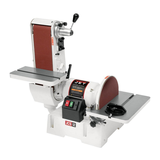
Combination Belt/Disc Sander
Model JSG-6DC
with optional open stand
with optional closed stand
for models with serial no. 20050451 and higher
JET
427 New Sanford Road
Part No. M-708599
LaVergne, Tennessee 37086
Revision H 05/2020
Ph.: 800-274-6848
ECR 200515104020
www.jettools.com
Copyright © 2014 JET
Advertisement
Table of Contents


Need help?
Do you have a question about the 708599 and is the answer not in the manual?
Questions and answers