Table of Contents
Advertisement
Operating Instructions and Parts Manual
Disc, Belt and Combination Disc/Belt Sanders
Models:
J-4200A
J-4200A-2
J-4202A
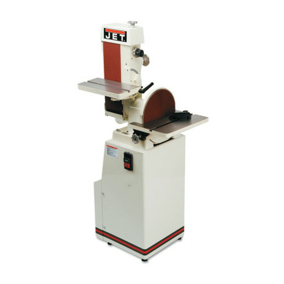
J-4200A Disc/Belt Sander
JET
427 New Sanford Road
LaVergne, Tennessee 37086
Ph.: 800-274-6848
www.jettools.com
J-4300A
J-4400A
J-4301A
J-4401A
J-4300A Belt Sander
This .pdf document is bookmarked
J-4400A Disc Sander
Part No. M-414551
Revision C1 01/2014
Copyright © 2014 JET
Advertisement
Table of Contents


Need help?
Do you have a question about the J-4200A and is the answer not in the manual?
Questions and answers
HI I HAVE A JET BELT SANDER MODEL J-4200A my front table broke i need the table and the opiece that mount to it i cant find any info on it
You can find a replacement front table and mounting piece for the Jet belt sander model J-4200A by ordering from the parts list provided in the manual. To order parts or reach the service department, call 1-800-274-6848 Monday through Friday. Have the model number and serial number of your machine ready when you call.
This answer is automatically generated