Table of Contents
Advertisement
This .pdf document is bookmarked
Operating Instructions and Parts Manual
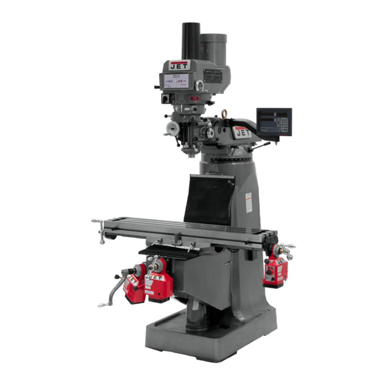
Variable Speed Turret Mill
Model JTM-4VS
Shown with optional accessories X-Axis Table Powerfeed and DRO
WALTER MEIER (Manufacturing) Inc.
427 New Sanford Road
LaVergne, Tennessee 37086
Part No. M-690182
Ph.: 800-274-6848
Revision H 04/2011
www.waltermeier.com
Copyright © 2011 Walter Meier (Manufacturing) Inc.
Advertisement
Table of Contents

Related Manuals for Jet JTM-4VS


Summary of Contents for Jet JTM-4VS
- Page 1 This .pdf document is bookmarked Operating Instructions and Parts Manual Variable Speed Turret Mill Model JTM-4VS Shown with optional accessories X-Axis Table Powerfeed and DRO WALTER MEIER (Manufacturing) Inc. 427 New Sanford Road LaVergne, Tennessee 37086 Part No. M-690182 Ph.: 800-274-6848 Revision H 04/2011 www.waltermeier.com...
-
Page 2: Warranty And Service
Walter Meier is consistently adding new products to the line. For complete, up-to-date product information, check with your local Walter Meier distributor, or visit waltermeier.com. WARRANTY JET products carry a limited warranty which varies in duration based upon the product (MW = Metalworking, WW = Woodworking). WHAT IS COVERED? This warranty covers any defects in workmanship or materials subject to the exceptions stated below. -
Page 3: Table Of Contents
Unpacking ..............................8 Contents of the Shipping Container......................8 Set-up and Installation..........................9 Preparing the Milling Machine for Service....................9 JTM-4VS Dimensions..........................10 JTM-4VS Overview and Terminology ......................11 Electrical Connections ..........................12 General Electrical Cautions ........................ 12 Wire Sizes ............................12 Lubrication ............................12 Operating Instructions .......................... - Page 4 Lead Screw Assembly .......................... 37 One-Shot Lubrication System ........................ 38 Electrical Connections – Single Phase only .................... 39 Electrical Connections – 3 Phase only ....................40...
- Page 5 Warning 1. Read and understand the entire owner’s manual before attempting assembly or operation. 2. Read and understand the warnings posted on the machine and in this manual. Failure to comply with all of these warnings may cause serious injury. 3.
- Page 6 21. Give your work undivided attention. Looking around, carrying on a conversation and “horse-play” are careless acts that can result in serious injury. 22. Maintain a balanced stance at all times so that you do not fall or lean against the cutters or other moving parts.
-
Page 7: Introduction
This manual is provided by Walter Meier (Manufacturing) Inc., covering the safe operation and maintenance procedures for a JET Model JTM-4VS Turret Milling Machine. This manual contains instructions on installation, safety precautions, general operating procedures, maintenance instructions and parts breakdown. This machine has been designed and constructed to provide years of trouble free operation if used in accordance with instructions set forth in this manual. -
Page 8: Unpacking
Table Adjustment Handles Unpacking Tool Box, containing: Hex Key Set (1.5-10mm) * Open shipping container and check for shipping damage. Report any damage immediately to your 17/19mm Box Wrench * distributor and shipping agent. Do not discard any Cross Point Screw Driver #2 * shipping material until the Turret Mill is assembled Flat Blade Screw Driver #2 * and running properly. -
Page 9: Set-Up And Installation
and-aft leveling. Be certain you get it level in Set-up and Installation BOTH directions. Preparing the Milling Machine for Service Mill must be supported equally 1. Remove any crating which may be covering the under all four corners. Failure to comply may cause machine on the pallet. -
Page 10: Jtm-4Vs Dimensions
JTM-4VS Dimensions Figure 2: Installation Diagram... -
Page 11: Jtm-4Vs Overview And Terminology
JTM-4VS Overview and Terminology Figure 3: Overview... -
Page 12: Electrical Connections
The motor switch controls a three-phase motor. The The JTM-4VS has been pre-wired for 230 volt motor can be switched from FWD to REV and back operation. To change from 230V to the other voltage... -
Page 13: Variable Speed Control
Figure 6 Variable Speed Control Change speed only while the spindle is turning. The vari-speed handwheel (A, Figure 7) is used to control the spindle speed. The speeds for high and low speed ranges are displayed on the panel on the front of the mill head (B, Figure 7). -
Page 14: Spindle Brake
Do not move the Quill Power Spindle Brake Feed Lever unless the motor is at a complete stop. When changing the lever The spindle brake lever is located on the upper left position, do it gently. If the gear does not engage, side of the mill head (Figure 8). -
Page 15: Feed Trip Cam Lever
Feed Trip Cam Lever Coarse Feed Handle The Feed Trip Cam Lever (A, Figure 12) is located on The Coarse Feed Handle (A, Figure 14) is located on the left side of the head behind the Manual Fine Feed the right side of head. The Coarse Feed Handle is Handwheel (B, Figure 12). -
Page 16: Depth Scale And Stop
Depth Scale and Stop Select feed rate with the Variable Speed Control Handwheel (E). Referring to Figure 15: 10. Set the Feed Rate Lever (B) to the feed rate The Depth Scale and Stop are used in drilling required for the tooling and material required. operations to set the depth of the drilled hole. -
Page 17: Draw Bar Operation - Changing Tooling
Draw Bar Operation - Changing Tooling Adjustments 1. Using the wrench provided with the machine, loosen the draw bar two or three turns (turn Mill Head – Left/Right Adjustment counterclockwise) using the draw bar hex (Figure 18). Make sure the machine base is secured to the floor before repositioning the mill head. -
Page 18: Mill Head - Fore/Aft Adjustment
4. Before applying final torque, check to make sure 2. Returning to upright position: the mill head is perpendicular to the worktable. a. When returning the mill head to its full upright 5. Set up a dial indicator in a collet and secure position, be sure to support the head by upward using the draw bar (refer to Figure 22). -
Page 19: Positioning The Ram
Positioning the Ram Positioning the Ram Fore and Aft 1. Loosen the two bolts (A, Figure 23) that lock the ram to its ways. Figure 24 Adjustment of Knee Gib The knee gib adjustment screw (A, Figure 24) is located under the chip wiper at the rear of the knee where it contacts the column. -
Page 20: Power Feed Trip Lever Mechanism
power feed. If not, readjust the mechanism until Power Feed Trip Lever Mechanism positive disengagement occurs when the quill is at the top of its stroke. Refer to Figure 25. 10. Check for correct operation using the coarse feed The power feed trip lever mechanism will need to be handle. - Page 21 4. Tighten the two nut locking screws. 5. Using the longitudinal table crank, move the table to the middle position. 6. Set up a dial indicator to check longitudinal backlash. Gently move the crank back and forth while watching the dial indicator. The backlash should be between 0.003 inch and 0.005 inch.
-
Page 22: Maintenance
Maintenance Before any intervention on the machine, disconnect it from the electrical supply by pulling out the plug or switching off the main switch! Failure to comply may cause serious injury. Lubrication The milling machine is equipped with a “one-shot” lubrication system. The system lubricates the lead screws and ways. -
Page 23: Replacement Of Drive Motor
10. Slowly release pressure on hydraulic ram until Replacement of Drive Motor the spring (ref. 8) is fully extended. Refer to Figure 30 and Head Assembly in the Parts 11. Remove the lengthening shaft (ref. 106), spring section. stop washer (ref. 9), spring (ref. 8) and outermost pulley (ref. -
Page 24: Replacement Of Vari-Speed Belt
Replacement of Vari-Speed Belt Refer to Figures 31 and 32, and Head Assembly in the Parts section. Disconnect electrical power to the machine before performing any maintenance. 1. Remove drive motor (refer to the Replacement of Drive Motor section). 2. Remove Quill Top Cover by removing three cap screws (Figure 31). -
Page 25: Replacement Of Quill Feed Clock Spring
7. Install the replacement spring (ref. 178) in the Replacement of Quill Feed Clock Spring spring cover (ref 177). Refer to the Spindle Assembly in the Parts section. 8. Install end of spring (ref. 178) over the pin (ref. 168) on pinion shaft (ref. 166). Disconnect electrical power to 9. -
Page 26: Head Assembly
Head Assembly... -
Page 27: Parts List For Head Assembly
Parts List for Head Assembly Index No. Part No. Description Size ....JTM4VS-HA ....Head Assembly w/ Motor................. 1 1 ....VS-001....Upper Housing ....................1 2 ....VS-002....Motor Pulley ....................1 ....VS-044A ....Motor Pulley Bushing (not shown) ..............1 3 ....TS-1503011 ....Set Screw ............M6 x 6........4 4 .... - Page 28 Index No. Part No. Description Size 55 .... TS-1503061 ....Hex Socket Cap Screw ........M6 x 25 ........1 56 .... VS-056....Brake Lock Handle ..................1 57 .... VS-057....Plastic Ball ..................... 2 58 .... VS-058....Brake Finger Pivot Stud .................. 1 59 .... VS-059....Brake Stud ..................... 2 60 ....
- Page 29 Index No. Part No. Description Size 115 ..JTM4VS-A002B ..Draw Bar Washer ................... 1 116 ..VS-116....Key ........................ 1 117 ..VS-117....Oval Head Screw..........3/16” x 1/2” ......1 118 ..VS-007....Snap Ring ...................... 4 119 ..VS-005A ....Plastic Sleeve....................2 120 ..
-
Page 30: Spindle Assembly
Spindle Assembly... - Page 31 Parts List for Spindle Assembly Index No. Part No. Description Size 1 ....TS-1533042 ....Screw ..............M5 x 10 ........6 2 ....HA-002 ....Bevel Pinion Washer..................1 3 ....HA-003 ....Feed Gear...................... 1 4 ....LA-161 ....Shaft Sleeve ....................1 5 ....
- Page 32 Index No. Part No. Description Size 78 .... LA-082 ....Overload Clutch Lockout ................. 1 79 .... LA-083 ....Safety Clutch Spring ..................1 80 .... LA-084 ....Overload Clutch ..........46T ........1 ....LA-084N....Overload Clutch (serial # 6100913 and up) ..50T ........1 81 ....
- Page 33 Index No. Part No. Description Size 153 ..LA-110 ....Quill Lock Sleeve .................... 1 155 ..LA-043 ....T-Bolt Assembly ..................... 4 156 ..LA-046 ....Spacer ......................4 157 ..LA-040 ....Lock Nut ......................4 158 ..HA-158 ....Screw ..............M4 x 5........2 159 ..
-
Page 34: Base Assembly
Base Assembly... -
Page 35: Parts List For Base Assembly
Parts List for Base Assembly Index No. Part No. Description Size 1 ....LB-001 ....Set Screw ............M6 x30........2 2 ....LB-023 ....Gear ......................1 3 ....LB-020 ....Ram Adapter ....................1 4 ....LB-004 ....Snap Ring ............S-28........2 5 ....LB-005 ....Rivet ......................5 6 .... - Page 36 Index No. Part No. Description Size 57 .... LK-022 ....Washer ......................1 58 .... MK-021 ....Bevel Gear ..................... 1 59 .... BB-6306ZZ ....Ball Bearing....................2 60 .... MK-019 ....Bearing Retainer Ring ..................1 61 .... MK-016 ....Elevating Screw ....................1 62 ....
-
Page 37: Lead Screw Assembly
Lead Screw Assembly Index No. Part No. Description Size 1 ....TS-0571052 ....Jam Nut ............1/2-20UNF ......3 2 ....LT-010C ....Handle ......................3 3 ....LT-010B ....Ball Crank ...................... 3 4 ....LT-009 ....Dial Lock Nut ....................3 5 ....LT-008 ....Dial ........................ 3 6 .... -
Page 38: One-Shot Lubrication System
One-Shot Lubrication System Index No. Part No. Description Size ....LT-8-A.....Hand Oiler Assembly (includes index #1,1A,4,5, 9) ........... 1 1 ....LT-8 ......Hand Oiler...................... 1 1A.... LT-8-SG ....Hand Oiler Sight Glass (w/gasket) ..............1 2 ....ALMP-04 ....Aluminum Pipe ..........3.5M ........1 .... -
Page 39: Electrical Connections - Single Phase Only
Electrical Connections – Single Phase only... -
Page 40: Electrical Connections - 3 Phase Only
Electrical Connections – 3 Phase only WALTER MEIER (Manufacturing) Inc. 427 New Sanford Road LaVergne, Tennessee 37086 Phone: 800-274-6848 www.waltermeier.com...
Need help?
Do you have a question about the JTM-4VS and is the answer not in the manual?
Questions and answers