Jet 22-44OSC Operating Instructions And Parts Manual
Oscillating drum sander
Hide thumbs
Also See for 22-44OSC:
- Specifications (2 pages) ,
- Operating instructions manual (24 pages)
Table of Contents
Advertisement
Advertisement
Table of Contents
Troubleshooting

Related Manuals for Jet 22-44OSC


Summary of Contents for Jet 22-44OSC
- Page 1 This .pdf document is bookmarked Operating Instructions and Parts Manual Oscillating Drum Sander Model 22-44OSC 427 New Sanford Road Part No. M-659006K LaVergne, Tennessee 37086 Revision D 03/2016 Ph.: 800-274-6848 ECR 16020409184 www.jettools.com Copyright © 2015 JET...
-
Page 2: Warranty And Service
JET sells through distributors only. The specifications listed in JET printed materials and on official JET website are given as general information and are not binding. JET reserves the right to effect at any time, without prior notice, those alterations to parts, fittings, and accessory equipment which they may deem necessary for any reason ®... -
Page 3: Table Of Contents
Table of Contents Warranty and Service ............................2 Table of Contents ..............................3 Warning ................................. 4 Introduction ................................6 Specifications ................................ 6 Features and Terminology ............................ 7 Unpacking ................................8 Shipping Contents ..............................8 ... -
Page 4: Warning
5. Do not use this sander for other than its intended use. If used for other purposes, JET disclaims any real or implied warranty and holds itself harmless from any injury that may result from that use. - Page 5 21. Make your workshop child proof with padlocks, master switches or by removing starter keys. 22. Give your work undivided attention. Looking around, carrying on a conversation and “horse-play” are careless acts that can result in serious injury. 23. Maintain a balanced stance at all times so that you do not fall or lean against moving parts. Do not overreach or use excessive force to perform any machine operation.
-
Page 6: Introduction
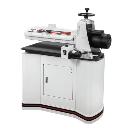
Introduction This manual is provided by JET covering the safe operation and maintenance procedures for a JET Model 22-44OSC Oscillating Drum Sander. This manual contains instructions on installation, safety precautions, general operating procedures, maintenance instructions and parts breakdown. This machine has been designed and constructed to provide consistent, long-term operation if used in accordance with instructions set forth in this manual. -
Page 7: Features And Terminology
Features and Terminology The illustration below shows the major components and features of the 22-44OSC Sander. These are referenced throughout the manual and will help to familiarize you with the operation and functions of the machine. Figure 1 – Features... -
Page 8: Unpacking
Unpacking Open shipping container and check for shipping damage. Report any damage immediately to your distributor and shipping agent. Do not discard any shipping material until the Drum Sander is assembled and running properly. Compare the contents of your container with the following parts list to make sure all parts are intact. -
Page 9: Assembly
Assembly Stand Assembly PPPPP 1. Position two stand sides (F ) on the 4. Secure the right side of the rear plate (G) to ground with the base down, about 3 feet the right stand side (F ) in the same manner apart with the openings toward the center. -
Page 10: Drum Head Installation
Drum Head Installation Tools required for assembly: 001 Flat head screwdriver 001 Set of open-end wrenches 001 Set of Hex wrenches 001 Adjustable wrench Referring to Figure 5: 1. Place the sander (C) onto the stand previously assembled. The sander is very heavy. Use a hoist or assistance when moving to avoid injury to self and equipment. -
Page 11: Dust Cover
Dust collection is mandatory for a safe work environment and extended abrasive life. The 22-44OSC is equipped with a 4” dust collection port at the top of the dust cover. It is designed to be used with standard 4” dust collection hose (B, Fig. - Page 12 5. Mark the trailing end of the strip where it crosses the right (inboard) end of the drum (Figure 11). 6. Remove the abrasive strip from the drum, and cut a taper as was done with the starting edge (see Figure 8). Note: The taper on the remaining roll can be used as the taper for the starting edge of the next strip to be cut.
-
Page 13: Grounding Instructions
permanent ground such as a properly grounded Grounding Instructions outlet box, as shown in Figure 16. Electrical connections must Extension Cords be made by a qualified electrician in If an extension cord is necessary, make sure the compliance with all relevant codes. This cord rating is suitable for the amperage listed on machine must be properly grounded to help the machine's motor plate. -
Page 14: Operating Controls
One revolution of the handwheel moves the drum approximately 1/16”. Oscillator Switch Referring to Figure 18: The 22-44OSC sander can be operated as a simple sander or as an oscillating sander. When operating as a linear sander, the sander Figure 18... -
Page 15: Adjustments
slippage of conveyor belt on the drive roller Adjustments during sanding operation; the conveyor belt is too loose if it can be stopped by hand pressure applied directly to the top of the conveyor belt. Depth Gauge Excessive belt tension can result in bent rollers, The depth gauge indicates the distance between bent brackets, and/or premature wearing of the the bottom of the sanding drum and the top of... -
Page 16: Conveyor Belt Replacement
Conveyor Belt Replacement 3. Insert gauge between the drum and con- veyor bed at the outer end of the drum 1. Unplug machine from wall (Figure 21). receptacle, and unplug the motor cord from the control box receptacle. 2. Raise drum to its highest position using the handwheel. -
Page 17: Fine Tuning Drum Alignment
Fine Tuning Drum Alignment Tension Roller Alignment Note: This is an operational test. Perform this The infeed and outfeed rollers are tensioned to alignment after you have become familiar with provide downward pressure on the workpiece to sander operation. prevent slippage on the feed conveyor. Tension rollers are set at the factory, but should be When sanding boards wider than the drum, inspected and may require adjustment as the... -
Page 18: Tension Roller Pressure Adjustment
Tension Roller Pressure Adjustment Drum Height Control Adjustment You can increase or decrease tension roller If the height control mechanism does not pressure by turning the screws on the tension operate easily or smoothly or there is excessive roller brackets (Figure 25). vertical movement or deflection of the drum carriage, perform the following adjustments. -
Page 19: Operation
Operation Do not start drum while in contact with stock! Before using your drum sander, review the previous pages in this manual on initial set-up For sanding with grits coarser than 80, you can and adjustment. In this section, you will learn lower the drum slightly. -
Page 20: Tips For Maximum Performance
When sanding stock with a cup or crown, place the crown up. This will stabilize the stock to help The versatility designed into the 22-44OSC prevent tipping or rocking during sanding. After drum sander allows it to be used for a wide... -
Page 21: Maintenance
Stock Feeding Angle Leave the dust collector on when cleaning dust from the drums. Also brush the conveyor belt Some pieces, because of their dimensions, will after cleaning operations. If not cleaned, the need to be fed into the machine at a 90° angle conveyor belt could allow stock to slip during (perpendicular to the drum). -
Page 22: Tracker Kit
The top slot is to be used if the bottom slot Tracker Kit wears out. Stock No.: 98-0080A 8. Install second Tracker opposite the first. Use Trackers dramatically reduce tracking adjust- both Trackers unless the second one does ments of conveyor belts. They are already not fit in conveyor or if conveyor belt is installed your... -
Page 23: Abrasives
susceptible to burnishing because of its open Abrasives pores. The abrasive material you choose will have a Cleaning Abrasive Strips substantial effect on the performance of your Regularly clean the abrasive strips on the drums sander. Variations in paper type, weight, coating with commercially available cleaning sticks, and durability all contribute to achieving your following the manufacturer’s directions. -
Page 24: Optional Accessories
Optional Accessories 98-2202 Infeed/Outfeed Tables Troubleshooting Troubleshooting – Motor and Electrical Problems Trouble Probable Cause Remedy Check plug connections. Connect main No incoming power. cord to power source, and motor cord into control box receptacle. Sander will not start. Circuit fuse blown or breaker tripped. Replace fuse or re-set breaker. -
Page 25: Troubleshooting - Mechanical Problems
Troubleshooting – Mechanical Problems Trouble Probable Cause Remedy Conveyor belt does not Align the shaft flats of the gear motor and Shaft coupling (#20, page 30) is loose or move, or runs the drive roller and tighten the shaft- unattached. `intermittently. -
Page 26: Troubleshooting - Operational Problems
- Worn v-belt – replace. - Warped drive pulley – replace. - Drum out of balance – contact your dealer or JET authorized service center. Sniping of wood Re-set tension rollers; see Tension Roller Tension rollers set too low. -
Page 27: Drum Head Assembly - Exploded View
Drum Head Assembly – Exploded View... -
Page 28: Drum Head Assembly - Parts List
Drum Head Assembly – Parts List Index No. Part No. Description Size 1 ....70-4102 ..... Motor................ 1-3/4HP, 115V ....1 ....70-4102MF ....Motor Fan (not shown)................... 1 ....70-4102MFC ..... Motor Fan Cover (not shown) ................ 1 .... - Page 29 107 .... 2244OSC-1114 ..Socket Head Cap Screw.......... M6 ......... 2 108 .... 2244OSC-1115 ..Plate....................... 2 109 .... 2244OSC-1116 ..Nylon Insert Lock Nut ..........M6 ......... 2 ....98-0060 ..... TufTool (not shown) ..................1 contact JET to find replacement abrasives...
-
Page 30: Conveyor And Motor Assembly - Exploded View
Conveyor and Motor Assembly – Exploded View... -
Page 31: Conveyor And Motor Assembly - Parts List
Conveyor and Motor Assembly – Parts List Index No. Part No. Description Size 1 ....323759 ...... Gear Motor............... 90 Volt DC..... 1 2 ....72-6014 ..... Strain Relief ....................1 3 ....72-5336 ..... Cord Set..............110-120V-75” ....1 4 .... -
Page 32: Gearbox Assembly
Gearbox Assembly Index No. Part No. Description Size ....2244OSC-GBA..Gearbox Assembly ..................1 1 ....2244OSC-201 ... Rubber Cover ....................1 2 ....2244OSC-202 ... Gear ....................... 1 3 ....BB-6002ZZ ....Ball Bearing ............. 6002ZZ......2 4 .... -
Page 33: Closed Stand Assembly
Closed Stand Assembly Index No. Part No. Description Size ....659006S ....Closed Stand Assembly................... 1 ....2244OSC-301 ... Stand Side ..................... 2 2 ....TS-0680041 ....Flat Washer ............. 3/8 ......... 4 3 ....TS-0060051 ....Hex Cap Screw ............3/8-16x1 ......4 4 .... -
Page 34: Infeed And Outfeed Tables
Infeed and Outfeed Tables Optional Accessory – Stock No.: 98-2202 Index No. Part No. Description Size 1 ....2244PLUS-501..Table ......................2 2 ....2244PLUS-502..Base Bracket ....................2 3 ....TS-0060051 ....Hex Cap Screw ............3/8-16x1 ......4 4 .... -
Page 35: Wiring Diagram
Wiring Diagram... - Page 36 427 New Sanford Road LaVergne, Tennessee 37086 Phone: 800-274-6848 www.jettools.com...
Need help?
Do you have a question about the 22-44OSC and is the answer not in the manual?
Questions and answers