Table of Contents
Advertisement
This .pdf document is bookmarked
Operating Instructions and Parts Manual
Drum Sander
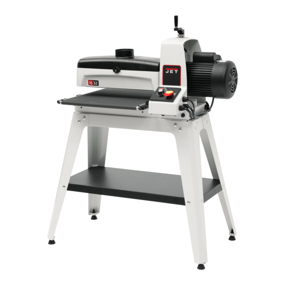
Models JWDS-1632, JWDS-1836
Model JWDS-1632 shown with optional infeed/outfeed tables
JET
427 New Sanford Road
LaVergne, Tennessee 37086
Part No. M-723520
Ph.: 800-274-6848
Edition 2 10/2016
www.jettools.com
Copyright © 2016 JET
Advertisement
Table of Contents


Need help?
Do you have a question about the JWDS-1632 and is the answer not in the manual?
Questions and answers