Jet JSG-96 Operating Instructions And Parts Manual
Benchtop disc/belt sander
Hide thumbs
Also See for JSG-96:
- Operating instructions manual (29 pages) ,
- Operating instructions and parts manual (24 pages) ,
- Operating instructions manual (20 pages)
Table of Contents
Advertisement
Advertisement
Table of Contents

Related Manuals for Jet JSG-96


Summary of Contents for Jet JSG-96
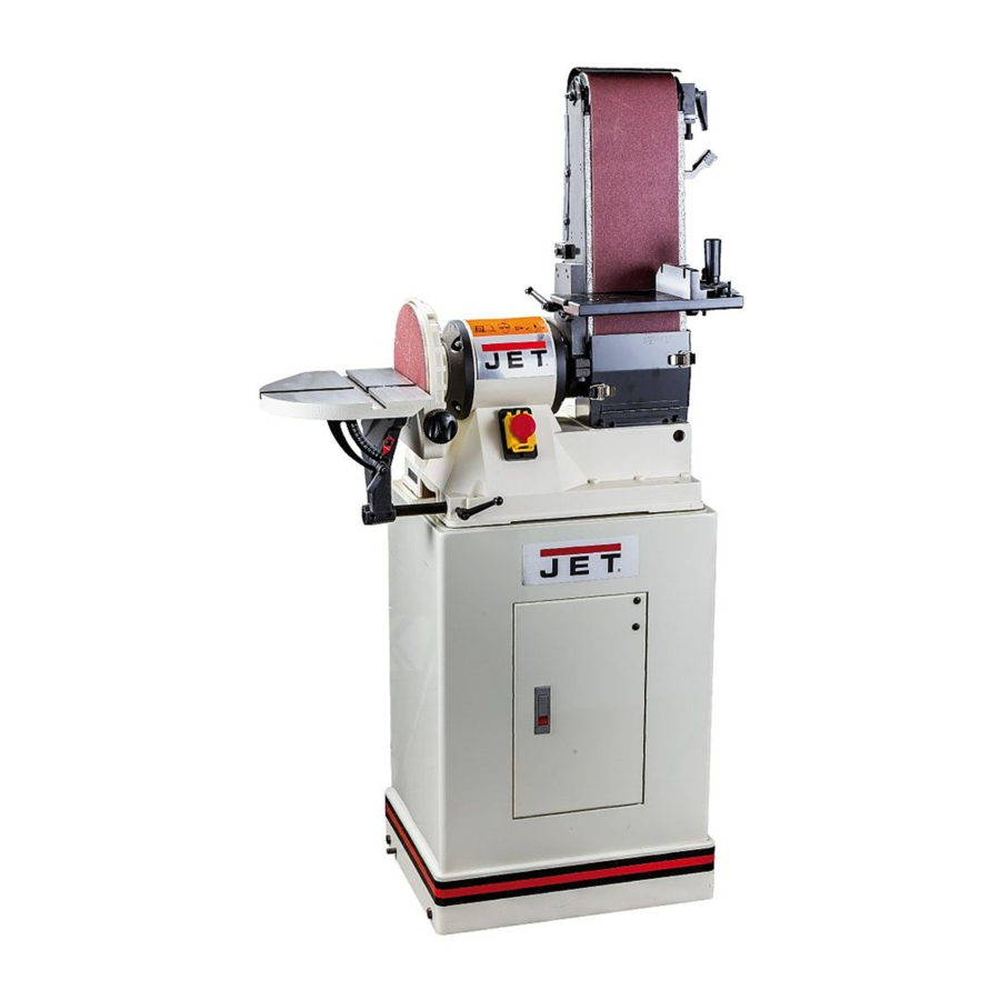
- Page 1 Operating Instructions and Parts Manual Benchtop Disc/Belt Sander Model JSG-96 (shown with optional closed stand 708597) WMH TOOL GROUP 2420 Vantage Drive Elgin, Illinois 60123 Part No. M-708595 Ph.: 800-274-6848 Revision G 10/04 www.wmhtoolgroup.com Copyright © WMH Tool Group...
-
Page 2: Warranty And Service
This manual has been prepared for the owner and operators of a JSG-96 Sander. Its purpose, aside from machine operation, is to promote safety through the use of accepted correct operating and maintenance procedures. Completely read the safety and maintenance instructions before operating or servicing the machine. -
Page 3: Warnings
This disc/belt sander is designed and intended for use by properly trained and experienced personnel only. If you are not familiar with the proper and safe operation of a disc/belt sander , do not use until proper training and knowledge has been obtained. - Page 4 ALWAYS DISCONNECT THE MACHINE FROM THE POWER SOURCE BEFORE SERVICING. • REDUCE THE RISK OF UNINTENTIONAL STARTING. Make sure the switch is in the off position before plugging in. • USE RECOMMENDED ACCESSORIES. The use of accessories and attachments not recommended by JET may cause hazards or risk of injury to persons.
-
Page 5: Grounding Instructions
115 Volt Operation As received from the factory, your sander is ready to run at 115 volt operation. This sander, when wired for 115 volt, is intended for use on a circuit that has an outlet and a plug that looks like the one illustrated in (A). -
Page 6: Table Of Contents
Specifications JSG-96 Stock Number... 708595 Sanding Belt ... 6”W x 48”L Disc Diameter...9” Table Tilt (down)... 90° - 45° Dust Chute Diameter ...4” Belt Table ... 5-1/2"W x 11"L Disc Table ... 10"W x 12”L Motor...3/4HP, 115V, 60Hz, 1Ph, 4P Belt Speed (SFPM)... -
Page 7: Contents Of The Shipping Carton
Remove all contents from the shipping carton. Report any damage to your distributor. Do not discard any shipping material until the sander has been assembled and is running properly. Open Stand Assembly (Optional) 1. Match the hole patterns in the stand legs with the hole patterns in the stand top pieces. -
Page 8: Assembly
Stand or bench must be stable enough to support weight of machine. 1. Move the sander to a workbench or one of JET’s optional stands. Bolt the unit firmly to hold in place. -
Page 9: Sanding Belt Table Adjustment
Sanding Belt Table Adjustment WARNING Always disconnect the sander from the power source before servicing or making any adjustments. Failure to comply may cause serious injury! 1. Place a square on the sanding belt table with one edge along the graphite pad, or sanding belt (Figure 4). -
Page 10: Horizontal Sanding Workstop
1. Loosen the socket head cap screw (A, Fig. 7) so that the sanding belt can be rotated to the horizontal position. 2. Rotate the sander until the stop (B, Fig. 7) contacts the sander base. socket head cap screw. -
Page 11: Belt Tracking Adjustment
(C, Fig. 10). Note: To prevent the sanding belt from stretching and to prolong belt life, remove the belt tension from the sander if not using for a long period of time. Disc Table Adjustment 1. Disconnect machine from the power source. -
Page 12: Sanding Disc Replacement
5. Press the new disc firmly into place. Center Point The center point (A, Fig. 15) provided with the sander can be used for sanding circles. The center point can be locked in position by tightening the set screws (B, Fig. 15). -
Page 13: Dust Collection
24 Grit 40 Grit Close 57617110 57617210 d Coat Open 57432910 57422110 Coat JSG-96 Sanding Disc PSA Aluminum Oxide Cloth Back Sanding Disc, Master Carton 25 9” 36 Grit 50 Grit Close 57697525 57697650 d Coat 60 Grit 80 Grit... -
Page 14: Troubleshooting
Machine vibrates excessively Abrasive belt keeps tearing Sanded edge not square Sanding marks on wood Troubleshooting Possible Cause 1. Sander unplugged from wall or motor 2. Fuse blown or circuit breaker tripped 3. Cord damaged 1. Extension cord too light or too long 2. -
Page 15: Parts Breakdowns & Parts List
Disc Sander Assembly Breakdown... - Page 16 46 ...JWBS18-403... Miter Gauge Body ..1 47 ...JSG96-147... Guide Bar..1 48 ...JWBS18-401... Lock Handle ..1 49 ...JWBS20-156... Guide Disc..1 50 ...JSG96-150... Pan Head Screw... 1/4x5/16 ... 1 Parts List For The JSG-96 Sander Disc Sander Assembly Description Size Qty.
- Page 17 Index Part 51 ...JSG96-151... Screw ... #10x5/16 ... 1 52 ...JWBS18-406... Pointer..1 53 ...JSG96-153... Bushing ..1 54 ...JSG96-154... I.D. Label..1 55 ...JSG96-155... Indication Label ..1 ...JSG96-MGA ... Miter Gauge Assembly (Items 38, 46 thru 52) ... 1 ...JSG96-CGA...
- Page 18 Belt Sander Assembly Breakdown...
- Page 19 Belt Sander Assembly Index Part Description Size Qty. 1...JSG96-201... Bracket..1 2...TS-0208071 ... Hex Socket Cap Screw... 5/16x1-1/4 ... 1 3...JSG96-203... Pin..1 4...JSG96-204... Fixed Plate ..1 5...TS-0680021 ... Flat Washer... 1/4 ... 8 6...JSG96-206... Screw ... 1/4x3/8 ... 3 7...JSG96-207...
- Page 20 Index Part Description Size Qty. 54 ...TS-0561011 ... Hex Nut ... 1/4 ... 2 55 ...JSG96-255... Set Screw... 1/4x3/4 ... 2 56 ...JSG96-256... Lock Handle* ... 5/16x1-1/4 ... 2 57 ...JSG96-257... Graphite Pad ..1 58 ...JSG96-155... Indication Label ..1 59 ...JSG96-259...
- Page 21 Open Stand Breakdown...
- Page 22 JSG-96 Open Stand Assembly Index Part Description Size Qty. 1...JSG96-401... Stand Top (front and rear, short)..2 2...JSG96-402... Stand Top (left and right, long) ..2 3...JSG96-403... Stand Leg w/Tool Holder ..2 4...JSG96-404... Stand Leg..2 5...JSG96-405...
- Page 23 Closed Stand Breakdown...
-
Page 24: Closed Stand Assembly
Index Part 1...JSG96-301... Base..1 2...JSG96-302... Lock Nut ... 3/8 ... 4 3...PJE-S05... Wheel..4 4...JSG96-304... Hex Head Screw* ... 3/8x2-1/2 ... 8 5...JSG96-305... Shaft ..1 6...PJN-S04 ... Eccentric Cam..2 7...JSG96-307... Set Screw... M6x10 ... 2 8...JSG96-308...
Need help?
Do you have a question about the JSG-96 and is the answer not in the manual?
Questions and answers