Advertisement
Quick Links
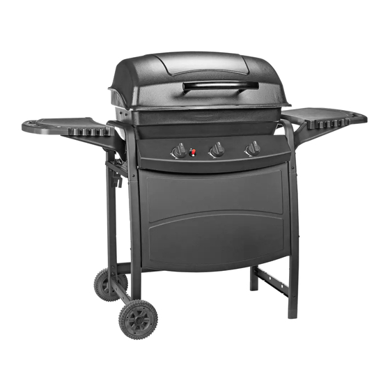
T360 Barbecue
Assembly Manual
85-3052-6 (G30531) Propane
1 YEAR LIMITED WARRANTY
READ AND SAVE MANUAL FOR FUTURE REFERENCE.
If pre-assembled, leave this manual with unit for
consumer's future reference.
For product inquiries, parts, warranty and
troubleshooting support, please call 1-877-707-5463.
Manual Revision #: 22092012 PDAT
Advertisement

Related Manuals for Master Chef T360


Summary of Contents for Master Chef T360
- Page 1 T360 Barbecue Assembly Manual 85-3052-6 (G30531) Propane 1 YEAR LIMITED WARRANTY READ AND SAVE MANUAL FOR FUTURE REFERENCE. If pre-assembled, leave this manual with unit for consumer’s future reference. For product inquiries, parts, warranty and troubleshooting support, please call 1-877-707-5463.
- Page 2 H E A V Y A R T I C L E N E E D S 2 T O L I F T THIS MANUAL MUST REMAIN WITH THE PRODUCT AT ALL TIMES To ORDER non-warranty replacement parts or accessories, or to register your warranty, please visit us on the web at www.masterchefbbqs.com CAUTION...
-
Page 3: Tools Needed For Assembly
HARDWARE PACK TOOLS NEEDED FOR ASSEMBLY KEY # DESCRIPTION PART NUMBER QUANTITY ¼”-20UNC Nut 31220-13000-036 • #2 Phillips screwdriver (long and short) ¼”-20UNCX13 Screw 20120-13013-036 ¼”-20UNCX30 Screw 20120-13030-036 • ¼” Slotted screwdriver (long and short) NO.10-24UNC Nut 31224-10000-036 • Adjustable wrench NO.10-24UNCX13 Screw 20124-10013-036 NO.10-24UNCX30 Screw... - Page 4 PARTS LIST PROPANE FOR 85 3052 6 G30531 KEY # QUANTITY DESCRIPTION PART NO. Top Lid Assembly G305-0R01-01 Upper Hinge G206-0002-03 Lid Handle G305-0090-01 Lid Bumper G560-5002-01 Burner Box Assembly G305-0S01-01 Lower Hinge G206-0010-03 Burner G305-AD00-01 Flame Tamer G305-0078-01 Cooking Grate G305-0006-01 Warming Rack G305-0080-01...
- Page 5 EXPLODED DIAGRAM PROPANE FOR 85 3052 6 G30531 ASSEMBLY SAFETY MANUAL AND CARE MANUAL HARDWARE PACK...
-
Page 6: Assembly Instructions
ASSEMBLY INSTRUCTIONS Insert left Cart Legs (DD & DE) into the Upper Leg Support Bar (DA), as shown. Attach Side Brace (DH) to left front Cart Leg (DD) using hardware, as shown in gure B. YOU WILL NEED: Attach the Support Bracket (DM) to the bottom of the left Cart Legs (DD &... - Page 7 ASSEMBLY INSTRUCTIONS Insert right Cart Legs (DB & DC) into the Upper Leg Support Bar (DA), as shown. Secure the Right, Front Cart Leg (DB) to the Upper Leg Support Bar (DA) using hardware, as shown. Attach the Support Bracket (DM) to the bottom of the right Cart Legs, as shown.
- Page 8 ASSEMBLY INSTRUCTIONS Assemble the two Back Braces (DK) to the left and right rear Cart Legs (DC & DE), as shown. YOU WILL NEED: Back view Attach the three Tank Exclusion rails (DL) to the Front Panel (DJ) and the lower Back Brace (DK), as shown.
- Page 9 ASSEMBLY INSTRUCTIONS NOTE: Turn cart assembly upside down. Place Wheel (DO) onto the Wheel Axle (DP). “Cone” side of wheel should be against cart leg, as shown in gure B. Insert Wheel Axle (DP) through wheel axle hole in the front and rear, of the left Cart Legs (DD & DE), as shown.
- Page 10 ASSEMBLY INSTRUCTIONS a. Position the Manifold Assembly (CB) through the back of the Control Panel (CA), and assemble. YOU WILL NEED: Back view b. Assemble the Igniter (CD) through the front of the Control Panel (CA), as shown. a. Assemble the Heat Shield (DI) to the Side Brace (DH), as shown.
- Page 11 ASSEMBLY INSTRUCTIONS a. Assemble the Burner (BC) into the Burner Box Assembly (BA), with the burner venturi tubes facing forward, as shown. YOU WILL NEED: b. Assemble hardware into Burner Box Assembly (BA), as shown. NOTE: This hardware will be used in a later step to support the Flame Tamer (BD).
- Page 12 ASSEMBLY INSTRUCTIONS c. Position the Burner Box Assembly (BA) onto the Burner Box Supports (DF & DG), as shown in gure A. ATTENTION: Before assembling, ensure the Burner (BC) engages the Manifold Assembly valves (CB). Attach the Burner Box Assembly (BA) to the Burner Box Support (DF &...
- Page 13 ASSEMBLY INSTRUCTIONS a. Assemble the front and rear right Side Shelf Brackets (EB & EC) to the right Side Shelf (EA), as shown. YOU WILL NEED: b. Assemble the right Side Shelf (EA) to the Upper Leg Support Bar (DA), as shown. YOU WILL NEED: c.
- Page 14 ASSEMBLY INSTRUCTIONS e. Assemble the left Side Burner Table (ED) to the Upper Leg Support Bar (DA), as shown. YOU WILL NEED: a. Assemble the Side Burner Valve Assembly (EK) to the Side Burner Table (ED). YOU WILL NEED: b. Position the Side Burner (EH) through the opening in the Side Burner Drip Pan (EG).
- Page 15 ASSEMBLY INSTRUCTIONS c. Connect the Side Burner (EH) to the Side Burner Valve (EK), using the venturi clip #20, as shown. YOU WILL NEED: d. Attach the end of the Side Burner Electrode Wire (EI) to the Igniter (CD), as shown in gure B.
- Page 16 ASSEMBLY INSTRUCTIONS Assemble the Lower Hinge (BB) on the back of the Burner Box Assembly (BA), as shown. YOU WILL NEED: Assemble the Upper Hinge (AB) to the Top Lid Assembly (AA). YOU WILL NEED:...
- Page 17 ASSEMBLY INSTRUCTIONS a. Assemble the Lid Handle (AC) to the Top Lid Assembly (AA). YOU WILL NEED: To assemble the Top Lid Assembly (AA) to the Burner Box Assembly (BA), position the Upper Hinge (AB) in between the Lower Hinge (BB), position hardware and lock into place using the Hitch Pins (#17).
- Page 18 ASSEMBLY INSTRUCTIONS Position the Flame Tamer (BD) into the Burner Box Assembly (BA). Note: The Flame Tamer (BD) should be placed onto the hardware assembled in step 11b. Position the Cooking Grate (BE) into the Burner Box Assembly (BA). To assemble the Warming Rack (BF), insert the stationary wire into the holes on the sides of the lid.
- Page 19 ASSEMBLY INSTRUCTIONS Hook the Grease Cup Hook (CE) to the bottom of the Burner Box Assembly (BA), as shown. Place the Grease Cup (CF) into the Grease Cup Hook (CE). Close Up a. Loosen the wing nut from the Tank Retainer Clip (DQ).
- Page 20 ASSEMBLY INSTRUCTIONS b. Attach the Regulator coupling nut (CG) to the LP cylinder valve. ATTENTION LP Cylinder is sold separately. Use only LP tanks that are equipped with an OPD (Over ll protection device). Fill and Leak check before attaching to the BBQ hose and regulator.
- Page 21 Visit www.masterchefbbqs.com to complete product registration ® Master Chef Customer Service 1-877-707-5463 Trileaf Distributions Trifeuil Toronto, Ontario M4S 2B8...
Need help?
Do you have a question about the T360 and is the answer not in the manual?
Questions and answers