Advertisement
Quick Links
TM
MC
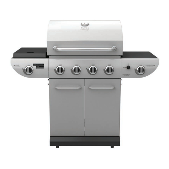
E500 Barbecue
Assembly Manual
85-3044-6 (G45311) Propane
85-3045-4 (G45312) Natural Gas
1 YEAR LIMITED WARRANTY
READ AND SAVE MANUAL FOR FUTURE REFERENCE.
Assemble your grill immediately.
Missing or damaged parts claims must be submitted within 30 days of purchase date.
For product inquiries, parts, warranty and troubleshooting support,
please call 1-855-453-2150.
Manual Revision #: 12022013 PD
ANS Z21.58b-2012-CSA 1.6b-2012
ANS Z21.58b-2012-CSA 1.6b-2012
ANS Z21.58b-2012-CSA 1.6b-2012
Advertisement

Related Manuals for Master Chef E500


Summary of Contents for Master Chef E500
- Page 1 E500 Barbecue Assembly Manual 85-3044-6 (G45311) Propane 85-3045-4 (G45312) Natural Gas 1 YEAR LIMITED WARRANTY READ AND SAVE MANUAL FOR FUTURE REFERENCE. Assemble your grill immediately. Missing or damaged parts claims must be submitted within 30 days of purchase date.
- Page 2 H E A V Y A R T I C L E N E E D S 2 T O L I F T THIS MANUAL MUST REMAIN WITH THE PRODUCT AT ALL TIMES To ORDER non-warranty replacement parts or accessories, or to register your warranty, please visit us on the web at www.masterchefbbqs.com CAUTION...
-
Page 3: Hardware Pack
HARDWARE PACK KEY # DESCRIPTION PART NUMBER QUANTITY TOOLS NEEDED FOR ASSEMBLY ¼”-20UNCX38 Screw 20120-13038-250 ¼”-20UNCX18 Screw 20120-13018-250 ¼”-20UNCX13 Screw 20120-13013-250 • #2 Phillips screwdriver (long and short) ¼” Nut 30220-13000-250 • ¼” Slotted screwdriver (long and short) φ7 Lock Washer 41400-07000-250 φ7 Washer 40300-07000-250... - Page 4 PARTS LIST (PROPANE) FOR 85-3044-6 (G45311) KEY # QUANTITY DESCRIPTION PART NO. Top lid G453-5100-01 Lid handle G513-0004-01 Thermometer G432-R200-01 Screw for top lid G453-0025-01 Lid bumper, front G508-0063-01 Lid bumper, rear G508-0033-01 Burner box weldment G453-2200-01 Flame tamer brace G453-0004-01 Main burner G517-7300-01...
- Page 5 EXPLODED DIAGRAM (PROPANE) FOR 85-3044-6 (G45311) SAFETY ASSEMBLY AND CARE MANUAL MANUAL HARDWARE PACK...
- Page 6 PARTS LIST (NATURAL GAS) FOR 85-3045-4 (G45312) KEY # QUANTITY DESCRIPTION PART NO. Top lid G453-5100-01 Lid handle G513-0004-01 Thermometer G432-R200-01 Screw for top lid G453-0025-01 Lid bumper, front G508-0063-01 Lid bumper, rear G508-0033-01 Burner box weldment G453-2200-01 Flame tamer brace G453-0004-01 Main burner G517-7300-01...
- Page 7 EXPLODED DIAGRAM (NATURAL GAS) FOR 85-3045-4 (G45312) SAFETY ASSEMBLY AND CARE MANUAL MANUAL HARDWARE PACK...
-
Page 8: Assembly Instructions
ASSEMBLY INSTRUCTIONS Separate the 2 different types of castors: 2 Locking Castors (EE) and 2 Regular Castors (EF). Note: Regular Castors (EF) need to be assembled to the front of the Bottom Shelf (ED), and Locking Castors (EE) need to be assembled to the back of the Bottom Shelf Front (ED), as shown in image A. - Page 9 ASSEMBLY INSTRUCTIONS THIS STEP REQUIRES 3 PEOPLE. DO NOT ATTEMPT ALONE. EXTREMELY HEAVY! Position the Top Lid Assembly and Burner Box Assembly (A & B) onto the Cart Assembly (C), as shown. Front View Attach the Upper Back Panel (BH) to both the Left And Right Side Panels (EB &...
- Page 10 ASSEMBLY INSTRUCTIONS Assemble the Door Support Rail (EA) to the Left and Right Upper Side Panels (EB and EC), as shown. WARNING: This part may have sharp edges. Wear protective gloves when assembling. Front View YOU WILL NEED: Close Up...
- Page 11 ASSEMBLY INSTRUCTIONS Attach the Match Holder (BI) to the left side panel of the Burner Box Assembly. YOU WILL NEED: Left side view a. Assemble infrared grease tray rails (DJ) to the infrared support frame (DC) located on the left sear stove side shelf (DA) as shown in figure A.
- Page 12 ASSEMBLY INSTRUCTIONS LEFT SIDE SHELF ASSEMBLY a. Mount the left side burner side shelf (DA and DB) onto the two support brackets, located on the left, upper side panel of the burner box (BA). Front, left side view b. Assemble the left side burner side shelf (DA and DB) to the upper side panel of the burner box (BA), by positioning hardware through the interior of the burner box (BA),...
- Page 13 ASSEMBLY INSTRUCTIONS a. Remove the hardware that is pre-assembled to the IR side burner valve (CC), as shown in figure A. Insert the side burner valve stem (CC) through the rear of the left side shelf fascia (DB) and assemble using the hardware removed. b.
- Page 14 ASSEMBLY INSTRUCTIONS a. Position the electrode spacer (#19) on the infrared support frame (DC) and then feed the infrared burner electrode (DE) through the opening on the right side of the infrared support frame (DC). Assemble using hardware as shown in figure A. NOTE: the infrared electrode (DE) set can be found attached to the infrared side burner valve (CC).
- Page 15 ASSEMBLY INSTRUCTIONS c. Use the side burner Venturi clip (#20) to connect the infrared side burner (DD) to the side burner valve (CC). YOU WILL NEED: View from underneath left side shelf d. Position the side burner cooking grate (DG) onto the infrared support frame (DC).
- Page 16 ASSEMBLY INSTRUCTIONS RIGHT SIDE SHELF ASSEMBLY TIP: Do not tighten until all hardware is in place. a. Mount the right side shelf (DH and DI ) onto the two support brackets, located on the right, upper side panel of the burner box (BA). Front, right side view b.
- Page 17 ASSEMBLY INSTRUCTIONS ELECTRONIC IGNITION ASSEMBLY Battery a. Remove the electronic ignition button (CH2) and the plastic nut from the Electronic Igniter Assembly (CH1) b. Position the Electronic Igniter Assembly (CH1) through the opening in the Right Side Shelf Plastic Nut Fascia (DI) and secure using the plastic nut.
- Page 18 ASSEMBLY INSTRUCTIONS a. Remove the hardware that is pre-assembled to the Rotisserie Burner Valve (BN), as shown in figure A Assemble the Rotisserie Burner Valve (BN) to the Right Side Shelf Fascia (DI), using the hardware removed. b. Assemble the Side Burner Control Knob (#17) to the Rotisserie Burner Valve (BN).
- Page 19 ASSEMBLY INSTRUCTIONS Back view Close up a. Assemble the Left and Right Tracks (CN and CM) for the Grease Tray (CL), as shown in figure YOU WILL NEED: Front view Close up, front view Close up, back view...
- Page 20 ASSEMBLY INSTRUCTIONS b. Insert the Grease Tray (CL) into the opening of the Upper Back Panel (BH). Back view Assemble the Door Handle (EI) to the Left and Right Door Assembly (EG and EH). Left door handle YOU WILL NEED: Right door handle YOU WILL NEED:...
- Page 21 ASSEMBLY INSTRUCTIONS a. Assemble the right door assembly (EH), to the bottom shelf (ED) by inserting the fixed pin (bottom of door) into the hole provided (figure B). Close up, bottom of door b. Assemble the top of the door assembly (EH) to the door support rail (EA), by pressing in the door support pin and aligning with the hole located on the top right corner of the door...
- Page 22 ASSEMBLY INSTRUCTIONS a. Position the Flame Tamer support braces (BB) over the Burner Box support pins (BA) as shown. b. Position the Flame Tamers (BE) into the Burner Box (BA). Close up...
- Page 23 ASSEMBLY INSTRUCTIONS Place the cooking grates (BF) into the burner box (BA). Insert the two small positioning rods of the warming rack (BG) into the rear panel of the burner box (BA).
- Page 24 LP cylinder valve. ATTENTION FOR YOUR SAFETY, DO NOT ATTEMPT TO LIGHT THIS BBQ UNTIL YOU HAVE REVIEWED PAGES 4-8 OF THE MASTER CHEF® SAFETY & CARE MANUAL. ALL SAFETY AND LEAK TESTS MUST BE PERFORMED BY THE END USER, PRIOR TO LIGHTING THIS BBQ.
- Page 25 Visit www.masterchefbbqs.com to complete product registration Master Chef® Customer Service 1-855-453-2150 Trileaf Distributions Trifeuil Toronto, Ontario M4S 2B8...
Need help?
Do you have a question about the E500 and is the answer not in the manual?
Questions and answers