D-Link DES-3526 Manual
Managed layer 2 ethernet switch 24-port 10/100mbps and 2ge ports
Hide thumbs
Also See for DES-3526:
- Command line interface reference manual (246 pages) ,
- User manual (230 pages) ,
- User manual (328 pages)

Related Manuals for D-Link DES-3526


Summary of Contents for D-Link DES-3526
- Page 1 D-Link ™ DES-3526/DES-3526DC Managed Layer 2 Ethernet Switch 24-port 10/100Mbps and 2GE ports Release 3.5 Manual...
- Page 2 Microsoft Corporation. Other trademarks and trade names may be used in this document to refer to either the entities claiming the marks and names or their products. D-Link Computer Corporation disclaims any proprietary interest in trademarks and trade names other than its own.
-
Page 3: Table Of Contents
Table of Contents Preface....................................vi Intended Readers ................................vii Typographical Conventions................................vii Notes, Notices, and Cautions............................vii Safety Instructions................................viii Safety Cautions....................................viii General Precautions for Rack-Mountable Products .......................... ix Protecting Against Electrostatic Discharge............................x Introduction....................................1 Gigabit Ethernet Technology................................1 Switch Description..................................... 1 Features...................................... - Page 4 IP Address Assignment..................................20 Connecting Devices to the Switch ..............................21 Web-based Switch Configuration ............................22 Introduction ..................................22 Login to Web Manager ..................................22 Web-based User Interface................................23 Web Pages ....................................... 24 Configuring the Switch ................................25 Switch Information................................25 IP Address ..................................26 Setting the Switch's IP Address using the Console Interface ......................
- Page 5 QoS....................................72 Port Bandwidth ....................................73 Scheduling ....................................... 75 802.1p Default Priority ..................................75 802.1p User Priority..................................76 Traffic Segmentation ..................................77 System Severity Alerts ..............................78 System Log Server ................................79 SNTP Settings ...................................81 Time Settings....................................81 Time Zone and DST ..................................83 Access Profile Table................................84 Configuring the Access Profile Table..............................
- Page 6 Enable Admin ....................................133 Secure Socket Layer (SSL) .............................133 Download Certificate..................................134 Ciphersuite..................................... 135 Secure Shell (SSH)................................136 SSH Configuration..................................137 SSH Algorithm ....................................138 SSH User Authentication................................139 SNMP Manager................................141 SNMP Settings ....................................141 SNMP User Table..................................142 SNMP View Table..................................145 SNMP Group Table ..................................
- Page 7 Save Changes ..................................179 Reset ....................................180 Reset System ...................................180 Reset Config..................................180 Reboot Device ....................................181 Logout ......................................181 D-Link Single IP Management ............................182 Single IP Management (SIM) Overview .........................182 SIM Using The Web Interface ............................183 Topology ..................................184 Tool Tips ..................................187 Right-Click ....................................189 Menu Bar .......................................
-
Page 8: Preface
DES-3526 / DES-3526DC Fast Ethernet Layer 2 Switch Preface The DES-3526/DES-3526DC Manual is divided into sections that describe the system installation and operating instructions with examples. Section 1, Introduction - Describes the Switch and its features. Section 2, Installation- Helps you get started with the basic installation of the Switch and also describes the front panel, rear panel, side panels, and LED indicators of the Switch. -
Page 9: Intended Readers
DES-3526 / DES-3526DC Fast Ethernet Layer 2 Switch Intended Readers The DES-3526 / DES-3526DC Manual contains information for setup and management of the Switch. This manual is intended for network managers familiar with network management concepts and terminology. Typographical Conventions... -
Page 10: Safety Instructions
DES-3526 / DES-3526DC Fast Ethernet Layer 2 Switch Safety Instructions Use the following safety guidelines to ensure your own personal safety and to help protect your system from potential damage. Throughout this document, the caution icon ( ) is used to indicate cautions and precautions that you need to review and follow. -
Page 11: General Precautions For Rack-Mountable Products
DES-3526 / DES-3526DC Fast Ethernet Layer 2 Switch • To help prevent electric shock, plug the system and peripheral power cables into properly grounded electrical outlets. These cables are equipped with three-prong plugs to help ensure proper grounding. Do not use adapter plugs or remove the grounding prong from a cable. -
Page 12: Protecting Against Electrostatic Discharge
DES-3526 / DES-3526DC Fast Ethernet Layer 2 Switch NOTE: A qualified electrician must perform all connections to DC power and to safety grounds. All electrical wiring must comply with applicable local, regional or national codes and practices. CAUTION: Never defeat the ground conductor or operate the equipment in the absence of a suitably installed ground conductor. -
Page 13: Introduction
Switch Description The DES-3526 is equipped with unshielded twisted-pair (UTP) cable ports providing dedicated 10 or 100 Mbps bandwidth. The Switch has 24 UTP ports and Auto MDI-X/MDI-II convertible ports that can be used for unlinking to another switch. These ports can be used for connecting PCs, printers, servers, hubs, routers, switches and other networking devices. -
Page 14: Features
NOTE: For the remainder of this manual both hardware versions of the Switch, the DES-3526 and DES-3526DC will be referred to as simply the Switch or the DES-3526 except where the differences are relevant. - Page 15 DES-3526 / DES-3526DC Fast Ethernet Layer 2 Switch Efficient self-learning and address recognition mechanism enables forwarding rate at wire speed •...
-
Page 16: Ports
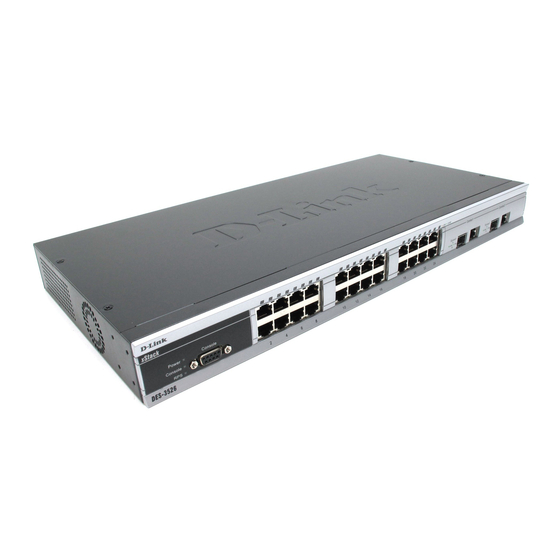
Front-Panel Components The front panel of the Switch consists of LED indicators for power and for each 10/100 Mbps twisted- pair ports, and two 1000BASE-T Mini-GBIC ports. The ports of the DES-3526 and DES-3526DC are identical. Figure 1- 1. Front Panel View of the DES-3526 The DES-3526DC does not support a redundant power supply;... -
Page 17: Led Indicators
DES-3526 / DES-3526DC Fast Ethernet Layer 2 Switch LED Indicators The Switch supports LED indicators for Power, Console, RPS (DES-3526 only) and Port LEDs. The following shows the LED indicators for the DES-3526 along with an explanation of each indicator. -
Page 18: Rear Panel Description
Rear Panel Description The rear panel of the Switch contains an AC power connector. Figure 1- 4. Rear panel view of the DES-3526 The AC power connector is a standard three-pronged connector that supports the power cord. Plug-in the female connector of the provided power cord into this socket, and the male side of the cord into a power outlet. - Page 19 DES-3526 / DES-3526DC Fast Ethernet Layer 2 Switch...
-
Page 20: Gigabit Combo Ports
DES-3526 / DES-3526DC Fast Ethernet Layer 2 Switch Gigabit Combo Ports In addition to the 24 10/100 Mbps ports, the Switch features two Gigabit Ethernet Combo ports. These two ports are 1000BASE-T copper ports (provided) and Mini-GBIC ports (optional). See the diagram below to view the two Mini-GBIC port modules being plugged into the Switch. -
Page 21: Installation
RS-232 console cable • If any item is found missing or damaged, please contact your local D-Link Reseller for replacement. Before You Connect to the Network The site where you install the Switch may greatly affect its performance. Please follow these guidelines for setting up the Switch. -
Page 22: Installing The Switch Without The Rack
DES-3526 / DES-3526DC Fast Ethernet Layer 2 Switch Installing the Switch Without the Rack When installing the Switch on a desktop or shelf, the rubber feet included with the Switch should first be attached. Attach these cushioning feet on the bottom at each corner of the device. Allow enough ventilation space between the Switch and any other objects in the vicinity. -
Page 23: Mounting The Switch In A Standard 19" Rack
DES-3526 / DES-3526DC Fast Ethernet Layer 2 Switch Mounting the Switch in a Standard 19" Rack CAUTION: Installing systems in a rack without the front and side stabilizers installed could cause the rack to tip over, potentially resulting in bodily injury under certain circumstances. -
Page 24: Connecting Dc Power To Des-3526Dc
DES-3526 / DES-3526DC Fast Ethernet Layer 2 Switch Connecting DC Power to DES-3526DC Follow the instructions below to connect the DC power supply of the DES-3526DC to the DC power source. Figure 2- 4. Power connections attached to contacts on assembly 1. -
Page 25: Connecting The Switch
DES-3526 / DES-3526DC Fast Ethernet Layer 2 Switch Section 3 Connecting The Switch Switch To End Node Switch To Hub or Switch Connecting To Network Backbone or Server NOTE: All 24 high-performance NWay Ethernet ports can support both MDI-II and MDI-X connections. -
Page 26: Switch To Hub Or Switch
DES-3526 / DES-3526DC Fast Ethernet Layer 2 Switch Switch to Hub or Switch These connections can be accomplished in a number of ways using a normal cable. A 10BASE-T hub or switch can be connected to the Switch via a twisted-pair Category 3, 4 or 5 UTP/STP •... -
Page 27: Introduction To Switch Management
DES-3526 / DES-3526DC Fast Ethernet Layer 2 Switch Section 4 Introduction To Switch Management Management Options Web-based Management Interface SNMP-Based Management Managing User Accounts Command Line Console Interface Through The Serial Port Connecting the Console Port (RS-232 DCE) First Time Connecting to The Switch... - Page 28 Read the next section for more information on setting up user accounts. See the DES-3526 Command Line Interface Reference Manual on the documentation CD for a list of all commands and additional information on using the CLI.
- Page 29 DES-3526 / DES-3526DC Fast Ethernet Layer 2 Switch Make sure the terminal or PC you are using to make this connection is configured to match these settings. If you are having problems making this connection on a PC, make sure the emulation is set to VT-100.
-
Page 30: First Time Connecting To The Switch
DES-3526 / DES-3526DC Fast Ethernet Layer 2 Switch First Time Connecting to The Switch The Switch supports user-based security that can allow you to prevent unauthorized users from accessing the Switch or changing its settings. This section tells how to log onto the Switch. -
Page 31: Password Protection
DES-3526 / DES-3526DC Fast Ethernet Layer 2 Switch Password Protection The DES-3526 does not have a default user name and password. One of the first tasks when settings up the Switch is to create user accounts. If you log in using a predefined administrator-level user name, you have privileged access to the Switch's management software. -
Page 32: Snmp Settings
MIB specifications and the protocol used to access this information over the network. The DES-3526 supports SNMP versions 1, 2c, and 3. You can specify which version of SNMP you want to use to monitor and control the Switch. The three versions of SNMP vary in the level of security provided between the management station and the network device. -
Page 33: Ip Address Assignment
DES-3526 / DES-3526DC Fast Ethernet Layer 2 Switch MIBs The Switch in the Management Information Base (MIB) stores management and counter information. The Switch uses the standard MIB-II Management Information Base module. Consequently, values for MIB objects can be retrieved from any SNMP-based network management software. In addition to the standard MIB-II, the Switch also supports its own proprietary enterprise MIB as an extended Management Information Base. -
Page 34: Connecting Devices To The Switch
DES-3526 / DES-3526DC Fast Ethernet Layer 2 Switch Alternatively, you can enter config ipif System ipaddress xxx.xxx.xxx.xxx/z. Where the x's represent the IP address to be assigned to the IP interface named System and the z represents the corresponding number of subnets in CIDR notation. -
Page 35: Web-Based Switch Configuration
IGMP Snooping Status Introduction All software functions of the DES-3526 can be managed, configured and monitored via the embedded web-based (HTML) interface. The Switch can be managed from remote stations anywhere on the network through a standard browser such as Opera, Netscape Navigator/Communicator, or Microsoft Internet Explorer. -
Page 36: Web-Based User Interface
DES-3526 / DES-3526DC Fast Ethernet Layer 2 Switch Figure 5- 2. Enter Network Password window Leave both the User Name field and the Password field blank and click OK. This will open the Web- based user interface. The Switch management features available in the web-based manager are explained below. -
Page 37: Web Pages
DES-3526 / DES-3526DC Fast Ethernet Layer 2 Switch Area 2 Presents a graphical near real-time image of the front panel of the Switch. This area displays the Switch's ports and expansion modules, showing port activity, duplex mode, or flow control, depending on the specified mode. -
Page 38: Configuring The Switch
DES-3526 / DES-3526DC Fast Ethernet Layer 2 Switch Section 6 Configuring the Switch Switch Information IP Address Advanced Settings Port Configuration Port Description Port Mirroring Link Aggregation LACP Port Setting MAC Notification IGMP Spanning Tree Forward Filtering VLANs Port Security... -
Page 39: Ip Address
The IP Address may initially be set using the console interface prior to connecting to it through the Ethernet. If the Switch IP address has not yet been changed, read the introduction of the DES-3526 Command Line Interface Manual or return to Section 4 of this manual for more information. - Page 40 DES-3526 / DES-3526DC Fast Ethernet Layer 2 Switch Figure 6- 2. IP Address Settings window To manually assign the Switch's IP address, subnet mask, and default gateway address: 1. Select Manual from the Get IP From drop-down menu. 2. Enter the appropriate IP Address and Subnet Mask.
-
Page 41: Setting The Switch's Ip Address Using The Console Interface
DES-3526 / DES-3526DC Fast Ethernet Layer 2 Switch The Switch will send out a DHCP broadcast request when it is powered up. The DHCP DHCP protocol allows IP addresses, network masks, and default gateways to be assigned by a DHCP server. If this option is set, the Switch will first look for a DHCP server to provide it with this information before using the default or previously entered settings. -
Page 42: Advanced Settings
DES-3526 / DES-3526DC Fast Ethernet Layer 2 Switch address assigned to the Switch must be known. The IP address may be set using the Command Line Interface (CLI) over the console serial port as follows: Starting at the command line prompt, enter the commands config ipif System ipaddress xxx.xxx.xxx.xxx/ •... - Page 43 DES-3526 / DES-3526DC Fast Ethernet Layer 2 Switch Minutes, 5 Minutes, 10 Minutes, 15 Minutes or Never. The default setting is 10 minutes. This field specifies the length of time a learned MAC Address will remain in the MAC Address Aging...
-
Page 44: Port Configurations
DES-3526 / DES-3526DC Fast Ethernet Layer 2 Switch Port Configurations This section contains information for configuring various attributes and properties for individual physical ports, including port speed and flow control. Clicking on Port Configurations in the Con- figuration menu will display the following window for the user:... -
Page 45: Port Description
Click Apply to implement the new settings on the Switch. Port Description The DES-3526 supports a port description feature where the user may name various ports on the Switch. To assign names to various ports, click the Port Description on the Configuration menu:... -
Page 46: Port Mirroring
DES-3526 / DES-3526DC Fast Ethernet Layer 2 Switch Figure 6- 5. Port Description Setting window Use the From and To pull down menu to choose a port or range of ports to describe, and then enter a description of the port(s). Click Apply to set the descriptions in the Port Description Table. -
Page 47: Link Aggregation
Port trunk groups are used to combine a number of ports together to make a single high-bandwidth data pipeline. The DES-3526 supports up to six port trunk groups with 2 to 8 ports in each group. A potential bit rate of 8000 Mbps can be achieved. - Page 48 DES-3526 / DES-3526DC Fast Ethernet Layer 2 Switch Figure 6- 7. Example of Port Trunk Group The Switch treats all ports in a trunk group as a single port. Data transmitted to a specific host (destination address) will always be transmitted over the same port in a trunk group. This allows packets in a data stream to arrive in the same order they were sent.
- Page 49 DES-3526 / DES-3526DC Fast Ethernet Layer 2 Switch are configured on the Switch, STP will block one entire group; in the same way STP will block a single port that has a redundant link. To configure port trunking, click on the Link Aggregation hyperlink in the Configuration folder to bring up the following window: Figure 6- 8.
- Page 50 DES-3526 / DES-3526DC Fast Ethernet Layer 2 Switch Figure 6- 10. Link Aggregation Settings window - Modify The user-changeable parameters are as follows: Parameter Description Group ID Select an ID number for the group, between 1 and 6. State Trunk groups can be toggled between Enabled and Disabled. This is used to turn a port trunking group on or off.
-
Page 51: Lacp Port Setting
DES-3526 / DES-3526DC Fast Ethernet Layer 2 Switch LACP Port Setting The LACP Port Setting window is used in conjunction with the Link Aggregation window to create port trunking groups on the Switch. Using the following window, the user may set which ports will be active and passive in processing and sending LACP control frames. -
Page 52: Mac Notification
DES-3526 / DES-3526DC Fast Ethernet Layer 2 Switch The user may set the following parameters: Parameter Description From/To A consecutive group of ports may be configured starting with the selected port. Mode Active - Active LACP ports are capable of processing and sending LACP control frames. -
Page 53: Mac Notification Port Settings
DES-3526 / DES-3526DC Fast Ethernet Layer 2 Switch MAC Notification Port Settings To change MAC notification settings for a port or group of ports on the Switch, click Port Settings in the MAC Notification folder, which will display the following window: Figure 6- 13. -
Page 54: Igmp
DES-3526 / DES-3526DC Fast Ethernet Layer 2 Switch Click Apply to implement changes made. IGMP Internet Group Management Protocol (IGMP) snooping allows the Switch to recognize IGMP queries and reports sent between network stations or devices and an IGMP host. When enabled for IGMP snooping, the Switch can open or close a port to a specific device based on IGMP messages passing through the Switch. - Page 55 DES-3526 / DES-3526DC Fast Ethernet Layer 2 Switch Figure 6- 15. IGMP Snooping Settings window The following parameters may be viewed or modified: Parameter Description VLAN ID This is the VLAN ID that, along with the VLAN Name, identifies the VLAN the user wishes to modify the IGMP Snooping Settings for.
-
Page 56: Static Router Ports Entry
DES-3526 / DES-3526DC Fast Ethernet Layer 2 Switch Route Timeout This is the maximum amount of time in seconds a route is kept in the forwarding table without receiving a membership report. Default = 260. This specifies the maximum amount of time in seconds between the Switch receiving... -
Page 57: Spanning Tree
802.1s MSTP. 802.1d STP will be familiar to most networking professionals. However, since 802.1w RSTP and 802.1s MSTP has been recently introduced to D-Link managed Ethernet switches, a brief introduction to the technology is provided below followed by a description of how to set up 802.1d STP, 802.1w RSTP and 802.1s MSTP. -
Page 58: W Rapid Spanning Tree
DES-3526 / DES-3526DC Fast Ethernet Layer 2 Switch one virtual bridge that runs a single spanning tree. Consequentially, frames assigned to different VLANs will follow different data routes within administratively established regions on the network, continuing to allow simple and full processing of frames, regardless of administrative errors in defining VLANs and their respective spanning trees. -
Page 59: Stp Bridge Global Settings
DES-3526 / DES-3526DC Fast Ethernet Layer 2 Switch 802.1d MSTP 802.1w RSTP 802.1d STP Forwarding Learning Discarding Discarding Disabled Discarding Discarding Blocking Discarding Discarding Listening Learning Learning Learning Forwarding Forwarding Forwarding Table 6- 1. Comparing Port States RSTP is capable of a more rapid transition to a forwarding state - it no longer relies on timer config- urations - RSTP compliant bridges are sensitive to feedback from other RSTP compliant bridge links. - Page 60 DES-3526 / DES-3526DC Fast Ethernet Layer 2 Switch figure 6- 18. STP Bridge Global Settings window - STP Figure 6- 19. STP Bridge Global Settings window - RSTP (default)
- Page 61 DES-3526 / DES-3526DC Fast Ethernet Layer 2 Switch Figure 6- 20. STP Bridge Global Settings window NOTE: The Hello Time cannot be longer than the Max. Age. Otherwise, a configuration error will occur. Observe the following formulas when setting the above parameters: Max.
-
Page 62: Mst Configuration Table
DES-3526 / DES-3526DC Fast Ethernet Layer 2 Switch and a BPDU has still not been received from the Root Bridge, the Switch will start sending its own BPDU to all other switches for permission to become the Root Bridge. If it turns out that your switch has the lowest Bridge Identifier, it will become the Root Bridge. - Page 63 DES-3526 / DES-3526DC Fast Ethernet Layer 2 Switch Parameter Description Configuration Name A previously configured name set on the Switch to uniquely identify the MSTI (Multiple Spanning Tree Instance). If a configuration name is not set, this field will show the MAC address to the device running MSTP.
- Page 64 DES-3526 / DES-3526DC Fast Ethernet Layer 2 Switch Figure 6- 23. Instance ID Settings window - CIST modify The user may configure the following parameters to configure the CIST on the Switch. Parameter Description MSTI ID The MSTI ID of the CIST is 0 and cannot be altered.
-
Page 65: Msti Settings
DES-3526 / DES-3526DC Fast Ethernet Layer 2 Switch MSTI ID Displays the MSTI ID previously set by the user. Type This field allows the user to choose a desired method for altering the MSTI settings. The user has four choices. -
Page 66: Stp Instance Settings
DES-3526 / DES-3526DC Fast Ethernet Layer 2 Switch Figure 6- 26. MSTI Settings window Parameter Description Instance ID <0> Displays the MSTI ID of the instance being configured. An entry of 0 in this field denotes the CIST (default MSTI). -
Page 67: Mstp Port Information
DES-3526 / DES-3526DC Fast Ethernet Layer 2 Switch Instance Type Displays the instance type(s) currently configured on the Switch. Each instance type is classified by a MSTI ID. CIST refers to the default MSTI configuration set on the Switch. Instance Status... - Page 68 DES-3526 / DES-3526DC Fast Ethernet Layer 2 Switch settings configurable in the STP Bridge Global Settings menu discussed previously. The following STP Port Settings fields can be set: Parameter Description From/To <Port 1> A consecutive group of ports may be configured starting with the selected port.
-
Page 69: Forwarding Filtering
DES-3526 / DES-3526DC Fast Ethernet Layer 2 Switch The default setting False, does not forward BPDU packets when STP is disabled. State <Disabled> This drop-down menu allows you to enable or disable STP for the selected group of ports. The default is Enabled. - Page 70 DES-3526 / DES-3526DC Fast Ethernet Layer 2 Switch Figure 6- 30. Static Multicast Forwarding Settings window The Static Multicast Forwarding Settings window displays all of the entries made into the Switch's static multicast forwarding table. Click the Add button to open the Setup Static Multicast For- warding Table window, as shown below: Figure 6- 31.
-
Page 71: Multicast Port Filtering Mode
DES-3526 / DES-3526DC Fast Ethernet Layer 2 Switch Multicast Port Filtering Mode The following figure and table describe how to set up multicast forwarding on the Switch. Open the Forwarding Filtering folder and click on the Multicast Port Filtering Mode Setup link to see the entry window below: Figure 6- 32. -
Page 72: Vlans
DES-3526 / DES-3526DC Fast Ethernet Layer 2 Switch VLANs Understanding IEEE 802.1p Priority Priority tagging is a function defined by the IEEE 802.1p standard designed to provide a means of managing traffic on a network where many different types of data may be transmitted simultaneously. -
Page 73: Ieee 802.1Q Vlans
DES-3526 / DES-3526DC Fast Ethernet Layer 2 Switch The DES-3526 supports IEEE 802.1Q VLANs and Port-Based VLANs. The port untagging function can be used to remove the 802.1Q tag from packet headers to maintain compatibility with devices that are tag-unaware. -
Page 74: Q Vlan Tags
DES-3526 / DES-3526DC Fast Ethernet Layer 2 Switch Figure 6- 33. IEEE 802.1Q Packet Forwarding 802.1Q VLAN Tags The figure below shows the 802.1Q VLAN tag. There are four additional octets inserted after the source MAC address. Their presence is indicated by a value of 0x8100 in the EtherType field. When a packet's EtherType field is equal to 0x8100, the packet carries the IEEE 802.1Q/802.1p tag. -
Page 75: Port Vlan Id
DES-3526 / DES-3526DC Fast Ethernet Layer 2 Switch Figure 6- 34. IEEE 802.1Q Tag The EtherType and VLAN ID are inserted after the MAC source address, but before the original EtherType/Length or Logical Link Control. Because the packet is now a bit longer than it was originally, the Cyclic Redundancy Check (CRC) must be recalculated. -
Page 76: Tagging And Untagging
DES-3526 / DES-3526DC Fast Ethernet Layer 2 Switch packet's destination address (found in the Switch's forwarding table). If the PVID of the port that received the packet is different from the PVID of the port that is to transmit the packet, the Switch will drop the packet. -
Page 77: Default Vlans
DES-3526 / DES-3526DC Fast Ethernet Layer 2 Switch dropped. If it has the same VID, the packet is forwarded and the destination port transmits it on its attached network segment. This process is referred to as ingress filtering and is used to conserve bandwidth within the Switch by dropping packets that are not on the same VLAN as the ingress port at the point of reception. -
Page 78: Static Vlan Entry
DES-3526 / DES-3526DC Fast Ethernet Layer 2 Switch Network resources such as printers and servers however, can be shared across VLANs. This is achieved by setting up overlapping VLANs. That is ports can belong to more than one VLAN group. - Page 79 DES-3526 / DES-3526DC Fast Ethernet Layer 2 Switch Figure 6- 37. 802.1Q Static VLAN window - Add To return to the Current 802.1Q Static VLANs Entries window, click the Show All Static VLAN Entries link. To change an existing 802.1Q VLAN entry, click the Modify button of the corresponding entry you wish to modify.
- Page 80 DES-3526 / DES-3526DC Fast Ethernet Layer 2 Switch Figure 6- 38. 802.1Q Static VLAN window - Modify The following fields can then be set in either the Add or Modify 802.1Q Static VLANs windows: Parameter Description VID (VLAN ID) Allows the entry of a VLAN ID in the Add window, or displays the VLAN ID of an existing VLAN in the Modify window.
-
Page 81: Gvrp Setting
DES-3526 / DES-3526DC Fast Ethernet Layer 2 Switch GVRP Setting In the Configuration menu, open the VLANs folder and click GVRP Setting. The 802.1Q Port Settings window, shown below, allows you to determine whether the Switch will share its VLAN configuration information with other GARP VLAN Registration Protocol (GVRP) enabled switches. -
Page 82: Traffic Control
DES-3526 / DES-3526DC Fast Ethernet Layer 2 Switch PVID The read-only field in the 802.1Q Port Table shows the current PVID assignment for each port, which may be manually assigned to a VLAN when created in the 802.1Q Port Settings table. The Switch's default is to assign all ports to the default VLAN with a VID of 1.The PVID is used by the port to tag outgoing, untagged packets, and... -
Page 83: Port Security
DES-3526 / DES-3526DC Fast Ethernet Layer 2 Switch Traffic or storm control is used to stop broadcast, multicast or ARP request storms that may result when a loop is created. The Destination Look Up Failure control is a method of shutting down a loop when a storm is formed because a MAC address cannot be located in the Switch's forwarding database and it must send a packet to all ports or all ports on a VLAN. - Page 84 DES-3526 / DES-3526DC Fast Ethernet Layer 2 Switch Figure 6- 41. Port Security Settings window The following parameters can be set: Parameter Description A consecutive group of ports may be configured starting with the selected port. From/To This pull-down menu allows you to enable or disable Port Security (locked MAC address Admin State table for the selected ports).
-
Page 85: Qos
DES-3526 / DES-3526DC Fast Ethernet Layer 2 Switch been reset. Click Apply to implement changes made. The DES-3526 supports 802.1p priority queuing Quality of Service. The following section discusses the implementation of QoS (Quality of Service) and benefits of using 802.1p priority queuing. Advantages of QoS QoS is an implementation of the IEEE 802.1p standard that allows network administrators a method of... -
Page 86: Port Bandwidth
CoS until there are no more packets for this CoS. The other CoS queues that have been given a nonzero value, and depending upon the weight, will follow a common weighted round-robin scheme. Remember that the DES-3526 has four priority queues (and four Classes of Service) for each port on the Switch. Port Bandwidth The bandwidth control settings are used to place a ceiling on the transmitting and receiving data rates for any selected port. - Page 87 DES-3526 / DES-3526DC Fast Ethernet Layer 2 Switch Figure 6- 43. Bandwidth Settings window The following parameters can be set or are displayed: Parameter Description From/To A consecutive group of ports may be configured starting with the selected port. Type This drop-down menu allows you to select between RX (receive), TX (transmit), and Both.
-
Page 88: Scheduling
DES-3526 / DES-3526DC Fast Ethernet Layer 2 Switch Scheduling Changing the output scheduling used for the hardware queues in the Switch can customize QoS. As with any changes to QoS implementation, careful consideration should be given to how network traffic in lower priority queues is affected. Changes in scheduling may result in unacceptable levels of packet loss or significant transmission delay. -
Page 89: 802.1P User Priority
802.1p User Priority The DES-3526 allows the assignment of a user priority to each of the 802.1p priorities. In the Configuration folder open the QoS folder and click 802.1p User Priority, to view the screen shown below. -
Page 90: Traffic Segmentation
DES-3526 / DES-3526DC Fast Ethernet Layer 2 Switch Figure 6- 46. QoS Class of Traffic window Once you have assigned a priority to the port groups on the Switch, you can then assign this Class to each of the 4 levels of 802.1p priorities. Click Apply to set your changes. -
Page 91: System Severity Alerts
DES-3526 / DES-3526DC Fast Ethernet Layer 2 Switch Figure 6- 47. Traffic Segmentation Setting window This page allows you to determine which port on a given switch will be allowed to forward packets to other ports on that switch. The user may set the following parameters:... -
Page 92: System Log Server
DES-3526 / DES-3526DC Fast Ethernet Layer 2 Switch Figure 6- 48. System Severity Settings Use the drop-down menus to configure the parameters described below. Parameter Description Severity Name Choose how the alerts are used from the drop-down menu. Select log to send the alert of the Severity Type configured to the Switch’s log for analysis. - Page 93 DES-3526 / DES-3526DC Fast Ethernet Layer 2 Switch Figure 6- 50. System Log Server window – Add The following parameters can be set: Parameter Description Index Syslog server settings index (1-4). Server IP The IP address of the Syslog server.
-
Page 94: Sntp Settings
DES-3526 / DES-3526DC Fast Ethernet Layer 2 Switch kernel messages user-level messages mail system system daemons security/authorization messages messages generated internally by syslog line printer subsystem network news subsystem UUCP subsystem clock daemon security/authorization messages FTP daemon NTP subsystem log audit... - Page 95 DES-3526 / DES-3526DC Fast Ethernet Layer 2 Switch Figure 6- 51. Current Time: Status window The following parameters can be set or are displayed: Parameter Description Current Time: Status Current Time Displays the time when the Switch was initially started for this session.
-
Page 96: Time Zone And Dst
DES-3526 / DES-3526DC Fast Ethernet Layer 2 Switch Time Zone and DST The following are windows used to configure time zones and Daylight Savings time settings for SNTP. Open the Configuration folder, then the SNTP folder and click on the Time Zone and DST link, revealing the following window. -
Page 97: Access Profile Table
DES-3526 / DES-3526DC Fast Ethernet Layer 2 Switch from GMT in +/- Mean Time (GMT.) HH:MM DST Repeating Settings - Using repeating mode will enable DST seasonal time adjustment. Repeating mode requires that the DST beginning and ending date be specified using a formula. For example, specify to begin DST on Saturday during the second week of April and end DST on Sunday during the last week of October. - Page 98 DES-3526 / DES-3526DC Fast Ethernet Layer 2 Switch Creating an access profile is divided into two basic parts. The first is to specify which part or parts of a frame the Switch will examine, such as the MAC source address or the IP destination address. The second part is entering the criteria the Switch will use to determine what to do with the frame.
- Page 99 DES-3526 / DES-3526DC Fast Ethernet Layer 2 Switch Figure 6- 54. Access Profile Configuration window (Ethernet) The following parameters can be set, for the Ethernet type: Parameter Description Profile ID (1-255) Type in a unique identifier number for this profile set. The number is used to set the relative priority for the profile.
- Page 100 DES-3526 / DES-3526DC Fast Ethernet Layer 2 Switch Figure 6- 55. Access Profile Configuration window (IP) The following parameters can be set, for IP: Parameter Description Profile ID (1-255) Type in a unique identifier number for this profile set. The number is used to set the relative priority for the profile.
- Page 101 DES-3526 / DES-3526DC Fast Ethernet Layer 2 Switch packet header. VLAN Selecting this option instructs the Switch to examine the VLAN part of each packet header and use this as the, or part of the criterion for forwarding. Source IP Mask Enter an IP address mask for the source IP address.
- Page 102 DES-3526 / DES-3526DC Fast Ethernet Layer 2 Switch Figure 6- 56. Access Profile Configuration window (Packet Content Mask) This screen will aid the user in Switch to mask packet headers beginning with the offset value specified. The following fields are used to configure the Packet configuring the Content Mask:...
- Page 103 DES-3526 / DES-3526DC Fast Ethernet Layer 2 Switch Offset This field will instruct the Switch to mask the packet header beginning with the offset value specified: value (0-15) - Enter a value in hex form to mask the packet from the •...
- Page 104 DES-3526 / DES-3526DC Fast Ethernet Layer 2 Switch Figure 6- 58. Access Rule Configuration window (IP) Configure the following Access Rule Configuration settings: Parameter Description Profile ID This is the identifier number for this profile set. Mode Select Permit to specify that the Switch, according to any additional rule, forward the packets that match the access profile added (see below).
- Page 105 DES-3526 / DES-3526DC Fast Ethernet Layer 2 Switch the QoS section of this manual. Replace DSCP (0-63) Select this option to instruct the Switch to replace the DSCP value (in a packet that meets the selected criteria) with the value entered in the adjacent field.
- Page 106 DES-3526 / DES-3526DC Fast Ethernet Layer 2 Switch Figure 6- 60. Access Rule Table window To remove a previously created rule, select it and click the button. To add a new Access Rule, click the Add button: Figure 6- 61. Access Rule Configuration window (Ethernet) To set the Access Rule for Ethernet, adjust the following parameters and click Apply.
- Page 107 DES-3526 / DES-3526DC Fast Ethernet Layer 2 Switch Access ID (1-65535) Type in a unique identifier number for this access or use Auto Assign. Type Selected profile based on Ethernet (MAC Address), IP address or Packet Content Mask. Ethernet instructs the Switch to examine the layer 2 part of each packet •...
- Page 108 DES-3526 / DES-3526DC Fast Ethernet Layer 2 Switch Figure 6- 62. Access Rule Display window (Ethernet) To configure the Access Rule for Packet Content Mask, open the Access Profile Table and click Modify for a Packet Content Mask entry. This will display the Access Rule Table.
- Page 109 DES-3526 / DES-3526DC Fast Ethernet Layer 2 Switch Figure 6- 64. Access Rule Configuration window (Packet Content Mask) To set the Access Rule for the Packet Content Mask, adjust the following parameters and click Apply. Parameter Description Profile ID This is the identifier number for this profile set.
- Page 110 DES-3526 / DES-3526DC Fast Ethernet Layer 2 Switch Ethernet instructs the Switch to examine the layer 2 part of each packet • header. IP instructs the Switch to examine the IP address in each frame's header. • Packet Content Mask instructs the Switch to examine the packet header.
-
Page 111: Pae Access Entity (802.1X)
DES-3526 / DES-3526DC Fast Ethernet Layer 2 Switch Figure 6- 65. Access Rule Display window (Packet Content) PAE Access Entity (802.1X) 802.1x Port-Based and MAC-Based Access Control The IEEE 802.1x standard is a security measure for authorizing and authenticating users to gain access to various wired or wireless devices on a specified Local Area Network by using a Client and Server based access control model. -
Page 112: Authentication Server
DES-3526 / DES-3526DC Fast Ethernet Layer 2 Switch Figure 6- 66. EAPOL Packet Utilizing this method, unauthorized devices are restricted from connecting to a LAN through a port to which the user is connected. EAPOL packets are the only traffic that can be transmitted through the specific port until authorization is granted. - Page 113 DES-3526 / DES-3526DC Fast Ethernet Layer 2 Switch Figure 6- 68. Authentication Server Authenticator The Authenticator (the Switch) is an intermediary between the Authentication Server and the Client. The Authenticator serves two purposes when utilizing 802.1x. The first purpose is to request certification information from the Client through EAPOL packets, which is the only information allowed to pass through the Authenticator before access is granted to the Client.
-
Page 114: Authentication Process
MAC address) is granted access and therefore successfully “unlocks” the port. Once unlocked, normal traffic is allowed to pass through the port. The D-Link implementation of 802.1x allows network administrators to choose between two types of Access Control used on the Switch, which are: Port-Based Access Control –... - Page 115 DES-3526 / DES-3526DC Fast Ethernet Layer 2 Switch RADIUS Server Ethernet Switch … 802.1X 802.1X 802.1X 802.1X 802.1X 802.1X 802.1X 802.1X 802.1X Client Client Client Client Client Client Client Client Client Network access controlled port Network access uncontrolled port Figure 6- 71. Example of Typical Port-Based Configuration...
-
Page 116: Mac-Based Network Access Control
DES-3526 / DES-3526DC Fast Ethernet Layer 2 Switch MAC-Based Network Access Control RADIUS Server Ethernet Switch … 802.1X 802.1X 802.1X 802.1X 802.1X 802.1X 802.1X 802.1X 802.1X 802.1X 802.1X 802.1X Client Client Client Client Client Client Client Client Client Client Client... - Page 117 DES-3526 / DES-3526DC Fast Ethernet Layer 2 Switch Figure 6- 73. 802.1X Authenticator Settings window To configure the settings by port, click on the hyperlinked port number under the Port heading, which will display the following table to configure:...
- Page 118 DES-3526 / DES-3526DC Fast Ethernet Layer 2 Switch Figure 6- 74. 802.1X Authenticator Settings window (Modify) This window allows you to set the following features: Parameter Description Enter the port or ports to be set. From [ ] To [ ] AdmCtrlDir <both>...
-
Page 119: Pae System Control
DES-3526 / DES-3526DC Fast Ethernet Layer 2 Switch TxPeriod [30 ] This sets the TxPeriod of time for the authenticator PAE state machine. This value determines the period of an EAP Request/Identity packet transmitted to the client. The default setting is 30 seconds. - Page 120 DES-3526 / DES-3526DC Fast Ethernet Layer 2 Switch Figure 6- 75. 802.1x Capability Settings window To set up the Switch's 802.1x port-based authentication, select which ports are to be configured in the From and To fields. Next, enable the ports by selecting Authenticator from the drop-down menu under Capability.
- Page 121 DES-3526 / DES-3526DC Fast Ethernet Layer 2 Switch Figure 6- 76. Initialize Port window This window allows you to initialize a port or group of ports. The Initialize Port Table in the bottom half of the window displays the current status of the port(s).
- Page 122 DES-3526 / DES-3526DC Fast Ethernet Layer 2 Switch From and To Select ports to be initialized. Port A read-only field indicating a port on the Switch. MAC Address The MAC address of the Switch connected to the corresponding port, if any.
-
Page 123: Radius Server
DES-3526 / DES-3526DC Fast Ethernet Layer 2 Switch Figure 6- 78. Reauthenticate Port window This window displays the following information: Parameter Description Port The port number of the reauthenticated port. MAC Address Displays the physical address of the Switch where the port resides. -
Page 124: Ip-Mac Binding
DES-3526 / DES-3526DC Fast Ethernet Layer 2 Switch Figure 6- 79. RADIUS Server Authentication Setting window This window displays the following information: Parameter Description Succession <First> Choose the desired RADIUS server to configure: First, Second or Third. RADIUS Server Set the RADIUS server IP. -
Page 125: Ip-Mac Binding Port
DES-3526 / DES-3526DC Fast Ethernet Layer 2 Switch enabled port, the system will block the access by dropping its packet. The maximum number of IP- MAC binding entries is dependant on chip capability (e.g. the ARP table size) and storage size of the device. -
Page 126: Ip-Mac Binding Blocked
DES-3526 / DES-3526DC Fast Ethernet Layer 2 Switch Figure 6- 81. IP-MAC Binding Table window IP-MAC Binding Blocked To view unauthorized devices that have been blocked by IP-MAC binding restrictions open the IP- MAC Binding Blocked window show below. Click IP-MAC Binding Blocked in the IP-MAC... -
Page 127: Limited Ip Multicast Range Settings
DES-3526 / DES-3526DC Fast Ethernet Layer 2 Switch Figure 6- 82. IP-MAC Binding Blocked window To find an unauthorized device that has been blocked by the IP-MAC binding restrictions, enter the VLAN name and MAC Address in the appropriate fields and click Find. To delete an entry click the delete button next to the entry’s MAC address. - Page 128 DES-3526 / DES-3526DC Fast Ethernet Layer 2 Switch Figure 6- 83. Limited Multicast VLAN Range window To configure Limited IP Multicast Range: 1. Choose the port or sequential range of ports using the From…To… port pull-down menus. 2. Use the remaining pull-down menus to configure the parameters described below:...
-
Page 129: Layer 3 Ip Networking
DES-3526 / DES-3526DC Fast Ethernet Layer 2 Switch Access Toggle the Access field to either Permit or Deny to limit or grant access to a specified range of Multicast addresses on a particular port or range of ports. Click Apply to implement the new settings on the Switch. -
Page 130: Dhcp/Bootp Relay
DES-3526 / DES-3526DC Fast Ethernet Layer 2 Switch DHCP/BOOTP Relay The relay hops count limit allows the maximum number of hops (routers) that the DHCP/BOOTP messages can be relayed through to be set. If a packet’s hop count is more than the hop count limit, the packet is dropped. - Page 131 DHCP Agent Information Option 82 Policy. The Implementation of DHCP Information Option 82 in DES-3526 The config dhcp_relay option_82 command configures the DHCP relay agent information option 82 setting of the switch. The formats for the circuit ID sub-option and the remote ID sub-option are as...
- Page 132 DES-3526 / DES-3526DC Fast Ethernet Layer 2 Switch NOTE: For the circuit ID sub-option of a standalone switch, the module field is always zero. Circuit ID sub-option format : VLAN Module Port 1 byte 1 byte 1 byte 1 byte...
- Page 133 DES-3526 / DES-3526DC Fast Ethernet Layer 2 Switch Figure 6- 88. DHCP/BOOTP Relay Interface Settings and DHCP/BOOTP Relay Interface Table window The following parameters may be configured or viewed. Parameter Description Interface The IP interface on the Switch that will be connected directly to the Server.
-
Page 134: Management
DES-3526 / DES-3526DC Fast Ethernet Layer 2 Switch Section 7 Management Security IP User Accounts Access Authentication Control (TACACS) Secure Sockets Layer (SSL) Secure Shell (SSH) SNMP Manager The following section will aid the user in configuring security functions for the Switch. The Switch includes various functions for security, including TACACS, Security IPs, SSL, SSH and SNMP, all discussed in detail in the following section. -
Page 135: Admin And User Privileges
DES-3526 / DES-3526DC Fast Ethernet Layer 2 Switch Figure 7- 3. User Accounts Modify Table window - Add Add a new user by typing in a User Name, and New Password and retype the same password in the Confirm New Password. Choose the level of privilege (Admin or User) from the Access Right drop- down menu. -
Page 136: Access Authentication Control
DES-3526 / DES-3526DC Fast Ethernet Layer 2 Switch System Utilities Factory Reset User Account Management Add/Update/Delete User Accounts View User Accounts Table 7- 1. Admin and User Privileges After establishing a User Account with Admin-level privileges, be sure to save the changes by opening the Maintenance folder, opening the Save Changes window and clicking the Save Configuration button. -
Page 137: Policy & Parameters
DES-3526 / DES-3526DC Fast Ethernet Layer 2 Switch the Switch, the Switch will ask the first Authentication Server Hosts for authentication. If no authentication is made, the second server host in the list will be queried, and so on. The built-in Authentication Server Groups can only have hosts that are running the specified protocol. -
Page 138: Application's Authentication Settings
DES-3526 / DES-3526DC Fast Ethernet Layer 2 Switch authentication attempts. Users failing to be authenticated after the set amount of attempts will be denied access to the Switch and will be locked out of further authentication attempts. Command line interface users will have to wait 60 seconds before another authentication attempt. -
Page 139: Authentication Server Group Settings
DES-3526 / DES-3526DC Fast Ethernet Layer 2 Switch Authentication Server Group Settings This window will allow users to set up Authentication Server Groups on the Switch. A server group is a technique used to group TACACS/XTACACS/TACACS+/RADIUS server hosts into user-defined categories for authentication using method lists. -
Page 140: Authentication Server Hosts
DES-3526 / DES-3526DC Fast Ethernet Layer 2 Switch NOTE: The three built in server groups can only have server hosts running same TACACS daemon. TACACS/XTACACS/TACACS+ protocols separate entities and are not compatible with each other. Authentication Server Hosts This window... -
Page 141: Login Method Lists
DES-3526 / DES-3526DC Fast Ethernet Layer 2 Switch IP Address The IP address of the remote server host the user wishes to add. Protocol The protocol used by the server host. The user may choose one of the following: TACACS - Enter this parameter if the server host utilizes the TACACS •... - Page 142 DES-3526 / DES-3526DC Fast Ethernet Layer 2 Switch To view the following window click Security Management > Access Authentication Control > Login Method Lists: Figure 7- 11. Login Method Lists Settings window The Switch contains one Method List that is set and cannot be removed, yet can be modified. To delete a Login Method List defined by the user, click the X under the Delete heading corresponding to the entry desired to be deleted.
-
Page 143: Enable Method Lists
DES-3526 / DES-3526DC Fast Ethernet Layer 2 Switch Parameter Description Method List Name Enter a method list name defined by the user of up to 15 characters. Method 1, 2, 3, 4 The user may add one, or a combination of up to four of the following authentication... - Page 144 DES-3526 / DES-3526DC Fast Ethernet Layer 2 Switch Figure 7- 14. Enable Method List Settings window To delete an Enable Method List defined by the user, click the X under the Delete heading corre- sponding to the entry desired to be deleted. To modify an Enable Method List, click on its hyperlinked Method List Name.
-
Page 145: Local Enable Password
DES-3526 / DES-3526DC Fast Ethernet Layer 2 Switch user in the next section entitled Local Enable Password must set the local enable password. none - Adding this parameter will require an authentication to access the • Switch. radius - Adding this parameter will require the user to be authenticated using •... -
Page 146: Enable Admin
DES-3526 / DES-3526DC Fast Ethernet Layer 2 Switch Enable Admin The Enable Admin window is for users who have logged on to the Switch on the normal user level, and wish to be promoted to the administrator level. After logging on to the Switch, users will have only user level privileges. -
Page 147: Download Certificate
DES-3526 / DES-3526DC Fast Ethernet Layer 2 Switch between client and host as they “exchange keys” in looking for a match and therefore authentication to be accepted to negotiate encryptions on the following level. 2. Encryption: The second part of the ciphersuite that includes the encryption used for encrypting the messages sent between client and host. -
Page 148: Ciphersuite
DES-3526 / DES-3526DC Fast Ethernet Layer 2 Switch Parameter Description Certificate Type Enter the type of certificate to be downloaded. This type refers to the server responsible for issuing certificates. This field has been limited to local for this firmware release. -
Page 149: Secure Shell (Ssh)
DES-3526 / DES-3526DC Fast Ethernet Layer 2 Switch EDE CBC SHA 3DES_EDE encryption and SHA Hash Algorithm. Use the pull-down menu to enable or disable this ciphersuite. This field is Enabled by default. RSA EXPORT with This ciphersuite combines the RSA Export key exchange and stream cipher RC4 RC4 40 MD5 encryption with 40-bit keys. -
Page 150: Ssh Configuration
DES-3526 / DES-3526DC Fast Ethernet Layer 2 Switch SSH Configuration The following window is used to configure and view settings for the SSH server and can be opened by clicking Security Management > Secure Shell (SSH) > SSH Configuration: Figure 7- 22. Current SSH Configuration Settings... -
Page 151: Ssh Algorithm
DES-3526 / DES-3526DC Fast Ethernet Layer 2 Switch SSH Algorithm The SSH Algorithm window allows the configuration of the desired types of SSH algorithms used for authentication encryption. There are four categories of algorithms listed and specific algorithms of each may be enabled or disabled by using their corresponding pull-down menus. All algorithms are enabled by default. -
Page 152: Ssh User Authentication
DES-3526 / DES-3526DC Fast Ethernet Layer 2 Switch ARC4 Use the pull-down to enable or disable the Arcfour encryption algorithm with Cipher Block Chaining. The default is Enabled. Use the pull-down to enable or disable the Cast128 encryption algorithm with Cipher Cast128-CBC Block Chaining. - Page 153 DES-3526 / DES-3526DC Fast Ethernet Layer 2 Switch Figure 7- 24. Current Accounts window In the example screen above, the User Account “Trinity” has been previously set using the User Accounts window in the Security Management folder. A User Account MUST be set in order to set the parameters for the SSH user.
-
Page 154: Snmp Manager
The DES-3526 supports the SNMP versions 1, 2c, and 3. You can specify which version of the SNMP you want to use to monitor and control the Switch. The three versions of SNMP vary in the level of security provided between the management station and the network device. -
Page 155: Snmp User Table
Use the SNMP V3 menus to select the SNMP version used for specific tasks. The DES-3526 supports the Simple Network Management Protocol (SNMP) versions 1, 2c, and 3. The administrator can specify the SNMP version used to monitor and control the Switch. The three versions of SNMP vary in the level of security provided between the management station and the network device. - Page 156 DES-3526 / DES-3526DC Fast Ethernet Layer 2 Switch Figure 7- 27. SNMP User Table Display window The following parameters are displayed: Parameter Description User Name An alphanumeric string of up to 32 characters. This is used to identify the SNMP users.
- Page 157 DES-3526 / DES-3526DC Fast Ethernet Layer 2 Switch Figure 7- 28. SNMP User Table Configuration window The following parameters can set: Parameter Description User Name Enter an alphanumeric string of up to 32 characters. This is used to identify the SNMP user.
-
Page 158: Snmp View Table
DES-3526 / DES-3526DC Fast Ethernet Layer 2 Switch SNMP View Table The SNMP View Table is used to assign views to community strings that define which MIB objects can be accessed by a remote SNMP manager. To view the SNMP View Table window, open the SNMP Manager folder under Security Management and click the SNMP View Table entry. -
Page 159: Snmp Group Table
DES-3526 / DES-3526DC Fast Ethernet Layer 2 Switch View Type Select Included to include this object in the list of objects that an SNMP manager can access. Select Excluded to exclude this object from the list of objects that an SNMP manager can access. - Page 160 DES-3526 / DES-3526DC Fast Ethernet Layer 2 Switch Figure 7- 32. SNMP Group Table Configuration window To add a new entry to the Switch's SNMP Group Table, click the Add button in the upper left-hand corner of the SNMP Group Table window. This will open the SNMP Group Table Configuration window, as shown below.
-
Page 161: Snmp Community Table Configuration
DES-3526 / DES-3526DC Fast Ethernet Layer 2 Switch Security Model SNMPv1 - Specifies that SNMP version 1 will be used. SNMPv2 - Specifies that SNMP version 2c will be used. The SNMPv2 supports both centralized distributed network management strategies. includes improvements in the Structure of Management Information (SMI) and adds some security features. -
Page 162: Snmp Host Table
DES-3526 / DES-3526DC Fast Ethernet Layer 2 Switch The following parameters can set: Parameter Description Community Name Type an alphanumeric string of up to 33 characters that is used to identify members of an SNMP community. This string is used like a password to give remote SNMP managers access to MIB objects in the Switch's SNMP agent. -
Page 163: Snmp Engine Id
DES-3526 / DES-3526DC Fast Ethernet Layer 2 Switch Figure 7- 36. SNMP Host Table Configuration window The following parameters can set: Parameter Description Host IP Address Type the IP address of the remote management station that will serve as the SNMP host for the Switch. -
Page 164: Monitoring
DES-3526 / DES-3526DC Fast Ethernet Layer 2 Switch Section 8 Monitoring Port Utilization CPU Utilization Packets Errors Size MAC Address Switch History Log IGMP Snooping Group IGMP Snooping Forwarding VLAN Status Router Port Port Access Control Layer 3 Feature Port Utilization The Utilization window displays the percentage of the total available bandwidth being used on the port. -
Page 165: Cpu Utilization
DES-3526 / DES-3526DC Fast Ethernet Layer 2 Switch Figure 8- 1. Utilization window The following field can be set: Parameter Description Time Interval Select the desired setting between 1s and 60s, where "s" stands for seconds. The default value is one second. -
Page 166: Packets
DES-3526 / DES-3526DC Fast Ethernet Layer 2 Switch Figure 8- 2. CPU Utilization window Click Apply to implement the configured settings. The window will automatically refresh with new updated statistics The information is described as follows: Parameter Description Time Interval Select the desired setting between 1s and 60s, where "s"... - Page 167 DES-3526 / DES-3526DC Fast Ethernet Layer 2 Switch Figure 8- 3. Rx Packets Analysis window (line graph for Bytes and Packets) To view the Received Packets Table, click the link View Table, which will show the following table:...
- Page 168 DES-3526 / DES-3526DC Fast Ethernet Layer 2 Switch Figure 8- 4. Rx Packets Analysis window (table for Bytes and Packets) The following fields may be set or viewed: Parameter Description Time Interval Select the desired setting between 1s and 60s, where "s" stands for seconds. The default value is one second.
-
Page 169: Umb Cast (Rx)
DES-3526 / DES-3526DC Fast Ethernet Layer 2 Switch UMB Cast (RX) Click the UMB Cast (RX) link in the Packets folder of the Monitoring menu to view the following graph of UMB cast packets received on the Switch. Figure 8- 5. Rx Packets Analysis window (line graph for Unicast, Multicast, and Broadcast Packets) -
Page 170: Transmitted (Tx)
DES-3526 / DES-3526DC Fast Ethernet Layer 2 Switch Figure 8- 6. Rx Packets Analysis window (table for Unicast, Multicast, and Broadcast Packets) The following fields may be set or viewed: Parameter Description Time Interval Select the desired setting between 1s and 60s, where "s" stands for seconds. The default value is one second. - Page 171 DES-3526 / DES-3526DC Fast Ethernet Layer 2 Switch Figure 8- 7. Tx Packets Analysis window (line graph for Bytes and Packets) To view the Transmitted (TX) Table, click the link View Table, which will show the following table: Figure 8- 8. Tx Packets Analysis window (table for Bytes and Packets)
-
Page 172: Errors
DES-3526 / DES-3526DC Fast Ethernet Layer 2 Switch Time Interval Select the desired setting between 1s and 60s, where "s" stands for seconds. The default value is one second. Select number of times the Switch will be polled between 20 and 200. The default Record Number value is 20. - Page 173 DES-3526 / DES-3526DC Fast Ethernet Layer 2 Switch To view the Received Error Packets Table, click the link View Table, which will show the following table: Figure 8- 10. Rx Error Analysis window (table) The following fields can be set:...
-
Page 174: Transmitted (Tx)
DES-3526 / DES-3526DC Fast Ethernet Layer 2 Switch View Table Clicking this button instructs the Switch to display a table rather than a line graph. View Line Chart Clicking this button instructs the Switch to display a line graph rather than a table. - Page 175 DES-3526 / DES-3526DC Fast Ethernet Layer 2 Switch Figure 8- 12. Tx Error Analysis window (table) The following fields may be set or viewed: Parameter Description Time Interval Select the desired setting between 1s and 60s, where "s" stands for seconds. The default value is one second.
-
Page 176: Size
DES-3526 / DES-3526DC Fast Ethernet Layer 2 Switch Size The Web Manager allows packets received by the Switch, arranged in six groups and classed by size, to be viewed as either a line graph or a table. Two windows are offered. -
Page 177: Mac Address
DES-3526 / DES-3526DC Fast Ethernet Layer 2 Switch Parameter Description Time Interval Select the desired setting between 1s and 60s, where "s" stands for seconds. The default value is one second. Select number of times the Switch will be polled between 20 and 200. The default Record Number value is 20. - Page 178 DES-3526 / DES-3526DC Fast Ethernet Layer 2 Switch Figure 8- 15. MAC Address Table window The following fields can be viewed or set: Parameter Description VLAN ID Enter a VLAN ID for the forwarding table to be browsed by. MAC Address Enter a MAC address for the forwarding table to be browsed by.
-
Page 179: Switch History
DES-3526 / DES-3526DC Fast Ethernet Layer 2 Switch The VLAN ID of the VLAN the port is a member of. MAC Address The MAC address entered into the address table. Port The port that the MAC address above corresponds to. -
Page 180: Igmp Snooping Group
DES-3526 / DES-3526DC Fast Ethernet Layer 2 Switch The Switch can record event information in its own logs, to designated SNMP trap receiving stations, and to the PC connected to the console manager. Click Next to go to the next page of the Switch His- tory Log. -
Page 181: Igmp Snooping Forwarding
Port Map These are the ports where the IGMP packets were snooped are displayed. NOTE: To configure IGMP snooping for the DES-3526, go to the Configuration folder and select IGMP. Configuration and other information concerning IGMP snooping may be found in Section 6 of this manual under IGMP. -
Page 182: Vlan Status
DES-3526 / DES-3526DC Fast Ethernet Layer 2 Switch Multicast Group The IP address of the multicast group. MAC Address The MAC address of the multicast group. Port Map These are the ports where the IGMP packets were snooped are displayed. -
Page 183: Port Access Control
DES-3526 / DES-3526DC Fast Ethernet Layer 2 Switch Figure 8- 20. Router Port window Port Access Control The following windows are used to monitor 802.1x statistics of the Switch, on a per port basis. To view the Port Access Control windows, open the monitoring folder and click the Port Access Control folder. - Page 184 DES-3526 / DES-3526DC Fast Ethernet Layer 2 Switch Figure 8- 21. Authenticator State window – Port-based 802.1x...
- Page 185 DES-3526 / DES-3526DC Fast Ethernet Layer 2 Switch Figure 8- 22. Show Authenticator State window – MAC-Based 802.1x This window displays the Authenticator State for individual ports on a selected device. To select unit within the switch stack, use the pull-down menu at the top of the window and click Apply. A polling interval between 1 and 60 seconds can be set using the drop-down menu at the top of the window and clicking OK.
-
Page 186: Layer 3 Feature
DES-3526 / DES-3526DC Fast Ethernet Layer 2 Switch Layer 3 Feature Browse ARP Table The ARP Table window may be found in the Monitoring menu in the Layer 3 Feature folder. This window will show current ARP entries on the Switch. To search a specific ARP entry, enter an interface name into the Interface Name or an IP address and click Find. -
Page 187: Maintenance
DES-3526 / DES-3526DC Fast Ethernet Layer 2 Switch Section 9 Maintenance TFTP Services Switch History Ping Test Save Changes Reboot Services Logout TFTP Services Trivial File Transfer Protocol (TFTP) services allow the Switch's firmware to be upgraded by transferring a new firmware file from a TFTP server to the Switch. A configuration file can also be loaded into the Switch from a TFTP server. -
Page 188: Download Configuration File
DES-3526 / DES-3526DC Fast Ethernet Layer 2 Switch Parameter Description Server IP Enter the IP address of the server from which you wish to download firmware. File Name Specify the path and filename of the firmware on the Server. Specify the purpose of the firmware: Type Download: Clicking this radio button will specify a download to the Switch. -
Page 189: Upload Configuration
DES-3526 / DES-3526DC Fast Ethernet Layer 2 Switch Enter the IP address of the TFTP server and specify the location of the switch settings file on the TFTP server. Click Start to record the IP address of the TFTP server and to initiate the file transfer. -
Page 190: Multiple Image Services
DES-3526 / DES-3526DC Fast Ethernet Layer 2 Switch Multiple Image Services The Multiple Image Services folder allows users of the xStack family of switches to configure and view information regarding firmware located on the Switch. The Switch allows two firmware images to be stored in its memory and either can be configured to be the boot up firmware for the Switch. -
Page 191: Config Firmware Image
DES-3526 / DES-3526DC Fast Ethernet Layer 2 Switch From States the IP address of the origin of the firmware. There are five ways firmware may be downloaded to the Switch. R – If the IP address has this letter attached to it, it denotes a firmware •... -
Page 192: Ping Test
1 and 255. Click Start to initiate the Ping program. Save Changes The DES-3526 has two levels of memory; normal RAM and non-volatile or NV-RAM. Configuration changes are made effective by clicking the Apply button. When this is done, the settings will be immediately applied to the switching software in RAM, and will immediately take effect. -
Page 193: Reset
DES-3526 / DES-3526DC Fast Ethernet Layer 2 Switch Click the OK button to continue. Once the Switch configuration settings have been saved to NV- RAM, they become the default settings for the Switch. These settings will be used every time the Switch is rebooted. -
Page 194: Reboot Device
DES-3526 / DES-3526DC Fast Ethernet Layer 2 Switch Figure 9- 12. Reset Config window Reboot Device The following window is used to restart the Switch. All of the configuration information entered from the last time Save Changes was executed will be lost. -
Page 195: D-Link Single Ip Management
SIM allows intermediate devices that do not support SIM. This enables the user to manage switches that are more than one hop away from the CS. The SIM group is a group of switches that are managed as a single entity. The DES-3526 may take on three different roles: 1. -
Page 196: Sim Using The Web Interface
SIM group. The Candidate Switch may join the SIM group through an automatic function of the DES-3526, or by manually configuring it to be a MS of a SIM group. A switch configured as a CaS is not a member of a SIM group and will take on the following characteristics: It is not a CS or MS of another Single IP group. -
Page 197: Topology
DES-3526 / DES-3526DC Fast Ethernet Layer 2 Switch Figure 10- 1. SIM Settings window (disabled) Change the SIM State to Enabled using the pull-down menu and click Apply. The window will then refresh and the SIM Settings window will look like this: Figure 10- 2. - Page 198 DES-3526 / DES-3526DC Fast Ethernet Layer 2 Switch Figure 10- 3. Java window Clicking the here link will setup the Java Runtime Environment on your server and lead you to the topology window, as seen below. Figure 10- 4. Single IP Management window-Tree View...
- Page 199 DES-3526 / DES-3526DC Fast Ethernet Layer 2 Switch to. The CS will have no entry in this field. MAC Address Displays the MAC Address of the corresponding Switch. Displays the full Model Name of the corresponding Switch. Model Name To view the Topology Map, click the View menu in the toolbar and then Topology, which will produce the following window.
-
Page 200: Tool Tips
DES-3526 / DES-3526DC Fast Ethernet Layer 2 Switch Icon Description Commander switch of other group Layer 2-member switch. Layer 3 member switch Member switch of other group Layer 2 candidate switch Layer 3 candidate switch Unknown device Non-SIM devices Tool Tips In the Topology view window, the mouse plays an important role in configuration and in viewing device information. - Page 201 DES-3526 / DES-3526DC Fast Ethernet Layer 2 Switch Figure 10- 6. Device Information Utilizing the Tool Tip Setting the mouse cursor over a line between two devices will display the connection speed between the two devices, as shown below.
-
Page 202: Right-Click
DES-3526 / DES-3526DC Fast Ethernet Layer 2 Switch Figure 10- 7. Port Speed Utilizing the Tool Tip Right-Click Right clicking on a device will allow the user to perform various functions, depending on the role of the Switch in the SIM group and the icon associated with it. -
Page 203: Commander Switch Icon
DES-3526 / DES-3526DC Fast Ethernet Layer 2 Switch Figure 10- 9. Property window Commander Switch Icon Figure 10- 10. Right-Clicking a Commander Icon The following options may appear for the user to configure: Collapse - to collapse the group that will be represented by a single icon. -
Page 204: Member Switch Icon
DES-3526 / DES-3526DC Fast Ethernet Layer 2 Switch Figure 10- 11. Property window Member Switch Icon Figure 10- 12. Right-Clicking a Member icon The following options may appear for the user to configure: Collapse - to collapse the group that will be represented by a single icon. -
Page 205: Candidate Switch Icon
DES-3526 / DES-3526DC Fast Ethernet Layer 2 Switch Figure 10- 13. Property window Candidate Switch Icon Figure 10- 14. Right-Clicking a Candidate icon The following options may appear for the user to configure: Collapse - to collapse the group that will be represented by a single icon. -
Page 206: Menu Bar
DES-3526 / DES-3526DC Fast Ethernet Layer 2 Switch Figure 10- 16. Property window This window holds the following information: Parameter Description Device Name This field will display the Device Name of the switches in the SIM group configured by the user. If no Device Name is configured by the name, it will be given the name default and tagged with the last six digits of the MAC Address to identify it. -
Page 207: Firmware Upgrade
DES-3526 / DES-3526DC Fast Ethernet Layer 2 Switch Group Add to group - add a candidate to a group. Clicking this option will reveal the following dialog box for the user • to enter a password for authentication from the Candidate Switch before being added to the SIM group. Click OK to enter the password or Cancel to exit the window. -
Page 208: Configuration File Backup/Restore
DES-3526 / DES-3526DC Fast Ethernet Layer 2 Switch Server IP Address where the firmware resides and enter the Path/Filename of the firmware. Click Download to initiate the file transfer. Figure 10- 19. Firmware Upgrade window Configuration File Backup/Restore This window is used to upgrade configuration files from the Commander Switch to the Member Switch. -
Page 209: Technical Specifications
DES-3526 / DES-3526DC Fast Ethernet Layer 2 Switch Appendix A Technical Specifications General Standards IEEE 802.3 10BASE-T Ethernet IEEE 802.3u 100BASE-TX Fast Ethernet IEEE 802.3ab 1000BASE-T Gigabit Ethernet IEEE 802.3z 1000BASE-T (SFP “Mini GBIC”) IEEE 802.1D Spanning Tree IEEE 802.1W Rapid Spanning Tree IEEE 802.1 P/Q VLAN... - Page 210 DES-3526 / DES-3526DC Fast Ethernet Layer 2 Switch Physical and Environmental DES-3526 AC Input: 100 – 120; 200 – 240 VAC, 50/60 Hz Internal power supply DES-3526 DC 60W DC Power Input: 48 V Output: 12V Power Consumption: 23 watts maximum...
-
Page 211: Cables And Connectors
DES-3526 / DES-3526DC Fast Ethernet Layer 2 Switch Appendix B Cables and Connectors When connecting the Switch to another switch, a bridge or hub, a normal cable is necessary. Please review these products for matching cable pin assignment. The following diagrams and tables show the standard RJ-45 receptacle/connector and their pin assignments. -
Page 212: Cable Lengths
DES-3526 / DES-3526DC Fast Ethernet Layer 2 Switch Appendix C Cable Lengths Use the following table to as a guide for the maximum cable lengths. Standard Media Type Maximum Distance Mini-GBIC 1000BASE-LX, Single-mode fiber module 10km 1000BASE-SX, Multi-mode fiber module... -
Page 213: Glossary
DES-3526 / DES-3526DC Fast Ethernet Layer 2 Switch Glossary 1000BASE-LX: A short laser wavelength on multimode fiber optic cable for a maximum length of 550 meters 1000BASE-SX: A long wavelength for a "long haul" fiber optic cable for a maximum length of 10 kilometers 100BASE-FX: 100Mbps Ethernet implementation over fiber. - Page 214 DES-3526 / DES-3526DC Fast Ethernet Layer 2 Switch forwarding: The process of sending a packet toward its destination by an internetworking device. full duplex: A system that allows packets to be transmitted and received at the same time and, in effect, doubles the potential throughput of a link.
- Page 215 DES-3526 / DES-3526DC Fast Ethernet Layer 2 Switch TCP/IP: A layered set of communications protocols providing Telnet terminal emulation, FTP file transfer, and other services for communication among a wide range of computer equipment. telnet: A TCP/IP application protocol that provides virtual terminal service, letting a user log in to another computer system and access a host as if the user were connected directly to the host.
-
Page 216: Limited Warranty
D-Link at an Authorized D-Link Service Office. The replacement Hardware need not be new or of an identical make, model or part; D-Link may in its discretion may replace the defective Hardware (or any part thereof) with any reconditioned product that D-Link reasonably determines is substantially equivalent (or superior) in all material respects to the defective Hardware. -
Page 217: Fcc Warning
Trademarks Copyright .2002 D-Link Corporation. Contents subject to change without prior notice. D-Link is a registered trademark of D-Link Corporation/D-Link Systems, Inc. All other trademarks belong to their respective proprietors. - Page 218 The customer must submit with the product as part of the claim a written description of the Hardware defect or Software nonconformance in sufficient detail to allow D-Link to confirm the same, along with proof of purchase of the product (such as a copy of the dated purchase invoice for the product) if the product is not registered.
- Page 219 Trademarks: D-Link is a registered trademark of D-Link Systems, Inc. Other trademarks or registered trademarks are the property of their respective owners. Copyright Statement: No part of this publication or documentation accompanying this product may be reproduced in any form or by any means or used to make any derivative such as translation, transformation, or adaptation without permission from D-Link Corporation/D-Link Systems, Inc., as...
- Page 220 Product Registration: Register online your D-Link product at http://support.dlink.com/register/ Product registration is entirely voluntary and failure to complete or return this form will not diminish your warranty rights.
- Page 221 (c) improper handling; (d) failure of goods or services not obtained from D-LINK or not subject to a then-effective D-LINK warranty or maintenance agreement; (e) improper use or storage; or (f) fire, water, acts of God or other catastrophic events. This warranty shall also not apply to any particular product if any D-LINK serial number has been removed or defaced in any way.
- Page 222 United Kingdom Telephone: +44-020-8731-5555 Facsimile: +44-020-8731-5511 www.dlink.co.uk...
- Page 223 Laufzeit der eingeschränkten Garantie Die Laufzeit der eingeschränkten Garantie beginnt mit dem Zeitpunkt, zu dem das Produkt von D-LINK gekauft wurde. Als Nachweis für den Zeitpunkt des Kaufs gilt der datierte Kauf- oder Lieferbeleg. Es kann von Ihnen verlangt werden, dass Sie zur Inanspruchnahme von Garantiediensten den Kauf des Produkts nachweisen. Wenn Ihre Hardware-Produkte der Marke D-LINK innerhalb der Laufzeit der eingeschränkten Garantie eine Reparatur benötigen, so sind Sie berechtigt, gemäß...
- Page 224 Edgware Road Colindale London NW9 5 AB Vereinigtes Königreich Telefon: +44-020-8731-5555 Fax: +44-020-8731-5511 www.dlink.com...
- Page 225 à ses spécifications ou aux interfaces requises ; (c) d’une mauvaise manipulation ; (d) d’une panne de biens ou de services acquis auprès d’une société tierce (non D-LINK) ou qui ne font pas l’objet d’un contrat D-LINK de garantie ou de maintenance en bonne et due forme ; (e) d’une mauvaise utilisation ou d’un rangement dans des conditions inadaptées ; ou (f) du feu, de l’eau, d’une catastrophe naturelle ou autre.
- Page 226 Fax : +44-020-8731-5511 www.dlink.co.uk...
- Page 227 El período de la garantía limitada del producto se inicia en la fecha en que se realizó la compra a D-LINK.
- Page 228 Teléfono: +44-020-8731-5555 Fax: +44-020-8731-5511 www.dlink.co.uk...
- Page 229 La presente garanzia non copre eventuali problemi derivanti da: (a) alterazioni o aggiunte non autorizzate; (b) negligenza, abuso o utilizzo improprio, compresa l’incapacità di far funzionare il prodotto in conformità con le specifiche e i requisiti di connessione; (c) movimentazione impropria; (d) guasto di prodotti o servizi non forniti da D-LINK o non soggetti a una garanzia successiva di D-LINK o a un accordo di manutenzione;...
- Page 230 Telefono: +44-020-8731-5555 Fax: +44-020-8731-5511 www.dlink.co.uk...
-
Page 231: Technical Support
Technical Support You can find software updates and user documentation on the D-Link website. Tech Support for customers within Australia: D-Link Technical Support over the Telephone: 1300-766-868 Monday to Friday 8:00am to 8:00pm EST Saturday 9:00am to 1:00pm EST D-Link Technical Support over the Internet: http://www.dlink.com.au... - Page 232 You can find software updates and user documentation on the D-Link website. Tech Support for customers within South Eastern Asia and Korea: D-Link South Eastern Asia and Korea Technical Support over the Telephone: +65-6895-5355 Monday to Friday 9:00am to 12:30pm, 2:00pm-6:00pm...
- Page 233 Technical Support You can find software updates and user documentation on the D-Link website. Tech Support for customers within India D-Link Technical Support over the Telephone: +91-22-26526741 +91-22-26526696 –ext 161 to 167 Monday to Friday 9:30AM to 7:00PM D-Link Technical Support over the Internet: http://ww.dlink.co.in...
- Page 234 Technical Support You can find software updates and user documentation on the D-Link website. D-Link provides free technical support for customers for the duration of the warranty period on this product. Customers can contact D-Link technical support through our web site or by phone.
- Page 235 Technical Support You can find software updates and user documentation on the D-Link website. Tech Support for customers within the U.A.E & North Africa: D-Link Technical Support over the Telephone: (971) 4-391-6480 (U.A.E) Sunday to Wednesday 9:00am to 6:00pm GMT+4 Thursday 9:00am to 1:00pm GMT+4 D-Link Middle East &...
- Page 236 You can find software updates and user documentation on the D-Link website. Tech Support for customers within South Africa and Sub Sahara Region: D-Link South Africa and Sub Sahara Technical Support over the Telephone: +27-12-665-2165 08600 DLINK ( For South Africa only )
- Page 237 Technical Support You can find updates and user documentation on the D-Link website Tech Support for Latin America customers: D-Link Technical Support over the followings Telephones: Argentina: 0800-666 1442 Monday to Friday 09:00am to 22:00pm Chile: 800-214 422 Monday to Friday 08:00am to 21:00pm...
- Page 238 Обновления программного обеспечения и документация доступны на Интернет-сайте D-Link. D-Link предоставляет бесплатную поддержку для клиентов в течение гарантийного срока. Клиенты могут обратиться в группу технической поддержки D-Link по телефону или через Интернет. Техническая поддержка D-Link: (095) 744-00-99 Техническая поддержка через Интернет http://www.dlink.ru...
- Page 239 El servicio de soporte técnico tiene presencia en numerosos países de la Región Latino América, y presta asistencia gratuita a todos los clientes de D-Link, en forma telefónica e internet, a través de la casilla soporte@dlinkla.com Soporte Técnico Help Desk Argentina: Teléfono: 0800-6661442 Lunes a Viernes 09:00 am a 22:00 pm...
- Page 240 Você pode encontrar atualizações de software e documentação de usuário no site da D-Link Brasil www.dlinkbrasil.com.br. A D-Link fornece suporte técnico gratuito para clientes no Brasil durante o período de vigência da garantia deste produto. Suporte Técnico para clientes no Brasil: Telefone São Paulo (11) 2185-9301...
- Page 241 友冠技術支援 台灣地區用戶可以透過我們的網站,電子郵件或電話與友 冠資訊技術支援人員聯絡。 支援服務時間從 週一到週五,上午8:30 a.m. 到 7:00 p.m Web: http://www.dlinktw.com.tw/ FAQ: http://www.dlinktw.com.tw/support.asp Email: dssqa_service@dlinktw.com.tw Phone: 0800-002-615 如果您是台灣地區以外的用戶,請參考使用手冊 中記載的D-Link 全球各地分公司的聯絡資訊...
- Page 242 Technical Support You can find software updates and user documentation on the D- Link website. D-Link provides free technical support for customers within the United States and within Canada for the duration of the warranty period on this product. U.S. and Canadian customers can contact D-Link technical support through our website, or by phone.
- Page 243 Technical Support You can find software updates and user documentation on the D-Link websites. D-Link provides free technical support for customers within Canada, the United Kingdom, and Ireland. Customers can contact D-Link technical support through our websites, or by phone.
- Page 244 Technische Unterstützung Aktualisierte Versionen von Software und Benutzerhandbuch finden Sie auf der Website von D-Link. D-Link bietet kostenfreie technische Unterstützung für Kunden innerhalb Deutschlands, Österreichs, der Schweiz und Osteuropas. Unsere Kunden können technische Unterstützung über unsere Website, per E-Mail oder telefonisch anfordern.
-
Page 245: Assistance Technique
Assistance technique Vous trouverez la documentation et les logiciels les plus récents sur le site web D-Link. Le service technique de D-Link est gratuit pour les clients Etats-Unis durant la période de garantie. Ceux-ci peuvent contacter le service technique de D-Link par notre site internet ou par téléphone. - Page 246 D-Link . D-Link ofrece asistencia técnica gratuita para clientes dentro de España durante el periodo de garantía del producto. Los clientes españoles pueden ponerse en contacto con la asistencia técnica de D-Link a través de nuestro sitio web o por teléfono. Asistencia Técnica de D-Link por teléfono:...
- Page 247 Supporto tecnico Gli ultimi aggiornamenti e la documentazione sono disponibili sul sito D-Link. Supporto tecnico per i clienti residenti in Italia D-Link Mediterraneo S.r.L. Via N. Bonnet 6/B 20154 Milano Supporto Tecnico dal lunedì al venerdì dalle ore 9.00 alle ore 19.00 con orario continuato...
- Page 248 Technical Support You can find software updates and user documentation on the D-Link website. D-Link provides free technical support for customers within Benelux for the duration of the warranty period on this product. Benelux customers can contact D-Link technical support through our website, or by phone.
- Page 249 Pomoc techniczna Najnowsze wersje oprogramowania i dokumentacji użytkownika można znaleźć w serwisie internetowym firmy D-Link. D-Link zapewnia bezpłatną pomoc techniczną klientom w Polsce w okresie gwarancyjnym produktu. Klienci z Polski mogą się kontaktować z działem pomocy technicznej firmy D-Link za pośrednictwem Internetu lub telefonicznie.
- Page 250 Technická podpora Aktualizované verze software a uživatelských příruček najdete na webové stránce firmy D-Link. D-Link poskytuje svým zákazníkům bezplatnou technickou podporu Zákazníci mohou kontaktovat oddělení technické podpory přes webové stránky, mailem nebo telefonicky Web: http://www.dlink.de E-Mail: support@dlink.de Telefon: +49 (1805)-2787 Telefonická...
- Page 251 Technikai Támogatás Meghajtó programokat és frissítéseket a D-Link Magyarország weblapjáról tölthet le. Telefonon technikai segítséget munkanapokon hétfőtől- csütörtökig 9.00 – 16.00 óráig és pénteken 9.00 – 14.00 óráig kérhet a (1) 461-3001 telefonszámon vagy a support@dlink.hu emailcímen. Magyarországi technikai támogatás : D-Link Magyarország...
- Page 252 Teknisk Support Du kan finne programvare oppdateringer og bruker dokumentasjon på D-Links web sider. D-Link tilbyr sine kunder gratis teknisk support under produktets garantitid. Kunder kan kontakte D-Links teknisk support via våre hjemmesider, eller på tlf. Teknisk Support: D-Link Teknisk telefon Support:...
- Page 253 Teknisk Support Du finder software opdateringer og bruger- dokumentation på D-Link’s hjemmeside. D-Link tilbyder gratis teknisk support til kunder i Danmark i hele produktets garantiperiode. Danske kunder kan kontakte D-Link’s tekniske support via vores hjemmeside eller telefonisk. D-Link teknisk support over telefonen: Tlf.
- Page 254 Teknisk Support På vår hemsida kan du hitta mer information om mjukvaru uppdateringar och annan användarinformation. D-Link tillhandahåller teknisk support till kunder i Sverige under hela garantitiden för denna produkt. Teknisk Support för kunder i Sverige: D-Link Teknisk Support via telefon: 0770-33 00 35 Vardagar 08.00-20.00...
- Page 255 技术支持 办公地址:北京市朝阳区建国路71号惠通时代广场C1座 202室 邮编: 100025 技术支持中心电话:8008868192/(028)85176977 技术支持中心传真:(028)85176948 维修中心地址:北京市海淀区中关村南大街9号理工大厦 1107室 邮编:100081 维修中心电话:(010)68477035/68477036/68477037 维修中心传真:(010)68477036 网址:http://www.dlink.com.cn 办公时间:周一到周五,早09:00到晚18:00 Ver 1.00...
-
Page 256: International Offices
102-106 Witch-Hazel Avenue France Highveld Technopark Le Florilege #.2, Allee de la Fresnerie India Centurion 78330 Fontenay le Fleury D-Link House, Kurla Bandra Complex Road, Gauteng France Off CST Road, Santacruz (East), Mumbai - 400098. Republic of South Africa TEL: 33-1-30238688 India... -
Page 257: Registration Card
8. What category best describes your company? Aerospace Engineering Education Finance Hospital Legal Insurance/Real Estate Manufacturing Retail/Chainstore/Wholesale Government Transportation/Utilities/Communication System house/company Other________________________________ 9. Would you recommend your D-Link product to a friend? Don't know yet 10.Your comments on this product?
Need help?
Do you have a question about the DES-3526 and is the answer not in the manual?
Questions and answers