D-Link DES-3526 User Manual
Layer 2 managed stackable fast ethernet switch
Hide thumbs
Also See for DES-3526:
- Command line interface reference manual (246 pages) ,
- User manual (328 pages) ,
- Manual (258 pages)

Related Manuals for D-Link DES-3526


Summary of Contents for D-Link DES-3526
-
Page 1: User Manual
User Manual DES-3526 / DES-3526DC Product Model: Layer 2 Managed Stackable Fast Ethernet Switch Release 3.60 ©Copyright 2005. All Rights Reserved... - Page 2 Corporation. Other trademarks and trade names may be used in this document to refer to either the entities claiming the marks and names or their products. D-Link Corporation disclaims any proprietary interest in trademarks and trade names other than its own.
-
Page 3: Table Of Contents
Table of Contents Preface......................................vi Intended Readers..................................vii Typographical Conventions ..................................vii Notes, Notices, and Cautions ............................... vii Safety Instructions..................................viii Safety Cautions ......................................viii General Precautions for Rack-Mountable Products ............................ix Protecting Against Electrostatic Discharge ..............................x Introduction......................................1 Gigabit Ethernet Technology ..................................1 Switch Description......................................1 Features...........................................2 Ports ..........................................2... - Page 4 Introduction....................................19 Login to Web Manager ....................................19 Web-based User Interface .....................................20 Web Pages........................................21 Configuring the Switch ..................................22 Switch Information..................................23 IP Address ....................................23 Setting the Switch's IP Address using the Console Interface ........................25 Advanced Settings..................................26 Port Configurations ..................................28 Port Description ...................................
- Page 5 Traffic Segmentation.....................................72 System Severity Alerts................................. 73 System Log Server ..................................73 SNTP Settings ....................................75 Time Setting........................................75 Time Zone and DST......................................76 Access Profile Table ..................................78 Configuring the Access Profile Table ................................78 PAE Access Entity (802.1X)................................ 89 802.1x Port-Based and MAC-Based Access Control ............................89 Authentication Process....................................91 Port-Based Network Access Control................................92 MAC-Based Network Access Control ................................93...
- Page 6 SNMP Manager..................................126 SNMP Settings......................................126 SNMP User Table .......................................127 SNMP View Table ......................................129 SNMP Group Table ....................................130 SNMP Community Table Configuration..............................131 SNMP Host Table .......................................132 SNMP Engine ID ......................................133 Monitoring ....................................... 134 Port Utilization................................... 134 CPU Utilization..................................135 Packets ....................................... 136 Received (RX) ......................................136 UMB Cast (RX) ......................................137 Transmitted (TX) ......................................139...
- Page 7 Reset Config....................................160 Reboot Device......................................160 Logout.........................................160 D-Link Single IP Management ................................ 161 Single IP Management (SIM) Overview............................ 161 SIM Using the Web Interface..............................163 Topology ....................................164 Tool Tips....................................166 Right-Click........................................167 Menu Bar ........................................171 Firmware Upgrade ..................................172 Configuration File Backup/Restore................................172 Technical Specifications ..................................
-
Page 8: Preface
DES-3526 / DES-3526DC Layer 2 Stackable Fast Ethernet Managed Switch User Manual Preface The DES-3526/DES-3526DC Manual is divided into sections that describe the system installation and operating instructions with examples. Section 1, Introduction - Describes the Switch and its features. -
Page 9: Intended Readers
DES-3526 / DES-3526DC Layer 2 Stackable Fast Ethernet Managed Switch User Manual Intended Readers The DES-3526 / DES-3526DC Manual contains information for setup and management of the Switch. This manual is intended for network managers familiar with network management concepts and terminology. -
Page 10: Safety Instructions
DES-3526 / DES-3526DC Layer 2 Stackable Fast Ethernet Managed Switch User Manual Safety Instructions Use the following safety guidelines to ensure your own personal safety and to help protect your system from potential damage. Throughout this document, the caution icon ( ) is used to indicate cautions and precautions that you need to review and follow. -
Page 11: General Precautions For Rack-Mountable Products
DES-3526 / DES-3526DC Layer 2 Stackable Fast Ethernet Managed Switch User Manual • Observe extension cable and power strip ratings. Make sure that the total ampere rating of all products plugged into the extension cable or power strip does not exceed 80 percent of the ampere ratings limit for the extension cable or power strip. -
Page 12: Protecting Against Electrostatic Discharge
DES-3526 / DES-3526DC Layer 2 Stackable Fast Ethernet Managed Switch User Manual Protecting Against Electrostatic Discharge Static electricity can harm delicate components inside your system. To prevent static damage, discharge static electricity from your body before you touch any of the electronic components, such as the microprocessor. You can do so by periodically touching an unpainted metal surface on the chassis. -
Page 13: Introduction
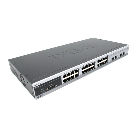
Please take note that if this device was purchased outside of Europe, certain cosmetic differences between the actual switch and images in this document will be apparent to the reader, such as the faceplate and the manual cover. The DES-3526/DES-3526DC has already joined the xStack family for the European market and is soon to be xStack converted, universally. -
Page 14: Features
DES-3526 / DES-3526DC Layer 2 Stackable Fast Ethernet Managed Switch User Manual NOTE: For the remainder of this manual, both hardware versions of the Switch, the DES-3526 and DES-3526DC, will be referred to as simply the Switch or the DES-3526 except where the differences are relevant. -
Page 15: Ports
DES-3526 / DES-3526DC Layer 2 Stackable Fast Ethernet Managed Switch User Manual Ports Twenty-four high-performance (MDI-X/MDI-II) ports for connecting to end stations, servers, hubs and other • networking devices. All UTP ports can auto-negotiate between 10Mbps and 100Mbps, half-duplex and full duplex, and feature flow control. -
Page 16: Led Indicators
DES-3526 / DES-3526DC Layer 2 Stackable Fast Ethernet Managed Switch User Manual LED Indicators The Switch supports LED indicators for Power, Console, RPS (DES-3526 only) and Port LEDs. The following shows the LED indicators for the DES-3526 along with an explanation of each indicator. LEDs and there corresponding meanings are displayed below. -
Page 17: Rear Panel Description
DES-3526 / DES-3526DC Layer 2 Stackable Fast Ethernet Managed Switch User Manual Rear Panel Description The rear panel of the Switch contains an AC power connector. Figure 1- 4. Rear panel view of the DES-3526 The AC power connector is a standard three-pronged connector that supports the power cord. Plug-in the female connector of the provided power cord into this socket, and the male side of the cord into a power outlet. -
Page 18: Gigabit Combo Ports
DES-3526 / DES-3526DC Layer 2 Stackable Fast Ethernet Managed Switch User Manual Gigabit Combo Ports In addition to the 24 10/100 Mbps ports, the Switch features two Gigabit Ethernet Combo ports. These two ports are 1000BASE-T copper ports (provided) and Mini-GBIC ports (optional). See the diagram below to view the two Mini-GBIC port modules being plugged into the Switch. -
Page 19: Installation
RS-232 console cable • If any item is found missing or damaged, please contact your local D-Link Reseller for replacement. Before You Connect to the Network The site where you install the Switch may greatly affect its performance. Please follow these guidelines for setting up the Switch. -
Page 20: Installing The Switch Without The Rack
DES-3526 / DES-3526DC Layer 2 Stackable Fast Ethernet Managed Switch User Manual Installing the Switch without the Rack When installing the Switch on a desktop or shelf, the rubber feet included with the Switch should first be attached. Attach these cushioning feet on the bottom at each corner of the device. -
Page 21: Mounting The Switch In A Standard 19" Rack
DES-3526 / DES-3526DC Layer 2 Stackable Fast Ethernet Managed Switch User Manual Mounting the Switch in a Standard 19" Rack CAUTION: Installing systems in a rack without the front and side stabilizers installed could cause the rack to tip over, potentially resulting in bodily injury under certain circumstances. Therefore, always install the stabilizers before installing components in the rack. -
Page 22: Connecting Dc Power To Des-3526Dc
DES-3526 / DES-3526DC Layer 2 Stackable Fast Ethernet Managed Switch User Manual Connecting DC Power to DES-3526DC Follow the instructions below to connect the DC power supply of the DES-3526DC to the DC power source. Figure 2- 4. Power connections attached to contacts on assembly 1. -
Page 23: Connecting The Switch
DES-3526 / DES-3526DC Layer 2 Stackable Fast Ethernet Managed Switch User Manual Section 3 Connecting the Switch Switch to End Node Switch to Hub or Switch Connecting To Network Backbone or Server NOTE: All 24 high-performance NWay Ethernet ports can support both MDI-II and MDI-X connections. -
Page 24: Switch To Hub Or Switch
DES-3526 / DES-3526DC Layer 2 Stackable Fast Ethernet Managed Switch User Manual Switch to Hub or Switch These connections can be accomplished in a number of ways using a normal cable. A 10BASE-T hub or switch can be connected to the Switch via a twisted-pair Category 3, 4 or 5 UTP/STP cable. -
Page 25: Introduction To Switch Management
DES-3526 / DES-3526DC Layer 2 Stackable Fast Ethernet Managed Switch User Manual Section 4 Introduction to Switch Management Management Options Web-based Management Interface SNMP-Based Management Managing User Accounts Command Line Console Interface through the Serial Port Connecting the Console Port (RS-232 DCE) - Page 26 12. Enter the commands to complete your desired tasks. Many commands require administrator-level access privileges. Read the next section for more information on setting up user accounts. See the DES-3526 Command Line Interface Reference Manual on the documentation CD for a list of all commands and additional information on using the CLI.
-
Page 27: First Time Connecting To The Switch
Password Protection The DES-3526 does not have a default user name and password. One of the first tasks when settings up the Switch is to create user accounts. If you log in using a predefined administrator-level user name, you have privileged access to the Switch's management software. - Page 28 DES-3526 / DES-3526DC Layer 2 Stackable Fast Ethernet Managed Switch User Manual NOTE: Passwords are case sensitive. User names and passwords can be up to 15 characters in length. The sample below illustrates a successful creation of a new administrator-level account with the user name "newmanager".
-
Page 29: Snmp Settings
The DES-3526 supports SNMP versions 1, 2c, and 3. You can specify which version of SNMP you want to use to monitor and control the Switch. The three versions of SNMP vary in the level of security provided between the management station and the network device. -
Page 30: Ip Address Assignment
DES-3526 / DES-3526DC Layer 2 Stackable Fast Ethernet Managed Switch User Manual IP Address Assignment Each Switch must be assigned its own IP Address, which is used for communication with an SNMP network manager or other TCP/IP application (for example BOOTP, TFTP). The Switch's default IP address is 10.90.90.90. You can change the default Switch IP address to meet the specification of your networking address scheme. -
Page 31: Connecting Devices To The Switch
DES-3526 / DES-3526DC Layer 2 Stackable Fast Ethernet Managed Switch User Manual Figure 4- 4. Assigning the Switch an IP Address In the above example, the Switch was assigned an IP address of 10.41.44.254 with a subnet mask of 255.0.0.0. The system message Success indicates that the command was executed successfully. -
Page 32: Web-Based Switch Configuration
IGMP Snooping Status Introduction All software functions of the DES-3526 can be managed, configured and monitored via the embedded web-based (HTML) interface. The Switch can be managed from remote stations anywhere on the network through a standard browser such as Opera, Netscape Navigator/Communicator, or Microsoft Internet Explorer. -
Page 33: Web-Based User Interface
Area 1 Select the menu or window to be displayed. The folder icons can be opened to display the hyper- linked menu buttons and subfolders contained within them. Click the D-Link logo to go to the D-Link website. Area 2 Presents a graphical near real-time image of the front panel of the Switch. -
Page 34: Web Pages
DES-3526 / DES-3526DC Layer 2 Stackable Fast Ethernet Managed Switch User Manual NOTICE: Any changes made to the Switch configuration during the current session must be saved in the Save Changes web menu (explained below) or use the command line interface (CLI) command save. -
Page 35: Configuring The Switch
DES-3526 / DES-3526DC Layer 2 Stackable Fast Ethernet Managed Switch User Manual Section 6 Configuring the Switch Switch Information IP Address Advanced Settings Port Configuration Port Description Port Mirroring Link Aggregation LACP Port Setting MAC Notification IGMP Spanning Tree... -
Page 36: Switch Information
The IP Address may initially be set using the console interface prior to connecting to it through the Ethernet. If the Switch IP address has not yet been changed, read the introduction of the DES-3526 Command Line Interface Manual or return to Section 4 of this manual for more information. - Page 37 DES-3526 / DES-3526DC Layer 2 Stackable Fast Ethernet Managed Switch User Manual To manually assign the Switch's IP address, subnet mask, and default gateway address: 1. Select Manual from the Get IP From drop-down menu. 2. Enter the appropriate IP Address and Subnet Mask.
-
Page 38: Setting The Switch's Ip Address Using The Console Interface
DES-3526 / DES-3526DC Layer 2 Stackable Fast Ethernet Managed Switch User Manual Auto Config When autoconfig is enabled, the Switch is instructed to get a configuration file via TFTP, and it State becomes a DHCP client automatically. The configuration file will be loaded upon booting up. In order to use Auto Config, the DHCP server must be set up to deliver the TFTP server IP address and configuration file name information in the DHCP reply packet. -
Page 39: Advanced Settings
DES-3526 / DES-3526DC Layer 2 Stackable Fast Ethernet Managed Switch User Manual Advanced Settings The Switch Information (Advanced Settings) window contains the main settings for all major functions for the Switch. To view the Advanced Settings window, click its link in the Configuration folder. This will enable the following window to be viewed and configured. - Page 40 DES-3526 / DES-3526DC Layer 2 Stackable Fast Ethernet Managed Switch User Manual Link Aggregation The algorithm that the Switch uses to balance the load across the ports that make up the Algorithm port trunk group is defined by this definition. Choose MAC Source, MAC Destination, MAC Src &...
-
Page 41: Port Configurations
DES-3526 / DES-3526DC Layer 2 Stackable Fast Ethernet Managed Switch User Manual Port Configurations This section contains information for configuring various attributes and properties for individual physical ports, including port speed and flow control. Clicking on Port Configurations in the Configuration menu will display the following window for the user: Figure 6- 4. -
Page 42: Port Description
DES-3526 / DES-3526DC Layer 2 Stackable Fast Ethernet Managed Switch User Manual Port Description The DES-3526 supports a port description feature where the user may name various ports on the Switch. To assign names to various ports, click the Port Description on the Configuration menu: Figure 6- 5. -
Page 43: Port Mirroring
DES-3526 / DES-3526DC Layer 2 Stackable Fast Ethernet Managed Switch User Manual Port Mirroring The Switch allows you to copy frames transmitted and received on a port and redirect the copies to another port. You can attach a monitoring device to the mirrored port, such as a sniffer or an RMON probe, to view details about the packets passing through the first port. -
Page 44: Link Aggregation
Port trunk groups are used to combine a number of ports together to make a single high-bandwidth data pipeline. The DES-3526 supports up to six port trunk groups with 2 to 8 ports in each group. A potential bit rate of 8000 Mbps can be achieved. - Page 45 DES-3526 / DES-3526DC Layer 2 Stackable Fast Ethernet Managed Switch User Manual Figure 6- 8. Port Link Aggregation Group window To configure port trunk groups, click the Add button to add a new trunk group and use the Link Aggregation Settings window (see example below) to set up trunk groups.
- Page 46 DES-3526 / DES-3526DC Layer 2 Stackable Fast Ethernet Managed Switch User Manual Parameter Description Group ID Select an ID number for the group, between 1 and 6. State Trunk groups can be toggled between Enabled and Disabled. This is used to turn a port trunking group on or off.
-
Page 47: Lacp Port Setting
DES-3526 / DES-3526DC Layer 2 Stackable Fast Ethernet Managed Switch User Manual LACP Port Setting The LACP Port Setting window is used in conjunction with the Link Aggregation window to create port trunking groups on the Switch. Using the following window, the user may set which ports will be active and passive in processing and sending LACP control frames. -
Page 48: Mac Notification
DES-3526 / DES-3526DC Layer 2 Stackable Fast Ethernet Managed Switch User Manual MAC Notification MAC Notification is used to monitor MAC addresses learned and entered into the forwarding database. MAC Notification Global Settings To globally set MAC notification on the Switch, open the following window by opening the MAC Notification folder and clicking the MAC Notification Global Settings link: Figure 6- 12. -
Page 49: Mac Notification Port Settings
DES-3526 / DES-3526DC Layer 2 Stackable Fast Ethernet Managed Switch User Manual MAC Notification Port Settings To change MAC notification settings for a port or group of ports on the Switch, click Port Settings in the MAC Notification folder, which will display the following window: Figure 6- 13. -
Page 50: Igmp
DES-3526 / DES-3526DC Layer 2 Stackable Fast Ethernet Managed Switch User Manual IGMP Internet Group Management Protocol (IGMP) snooping allows the Switch to recognize IGMP queries and reports sent between network stations or devices and an IGMP host. When enabled for IGMP snooping, the Switch can open or close a port to a specific device based on IGMP messages passing through the Switch. - Page 51 DES-3526 / DES-3526DC Layer 2 Stackable Fast Ethernet Managed Switch User Manual The following parameters may be viewed or modified: Parameter Description VLAN ID This is the VLAN ID that, along with the VLAN Name, identifies the VLAN the user wishes to modify the IGMP Snooping Settings for.
-
Page 52: Static Router Ports Entry
DES-3526 / DES-3526DC Layer 2 Stackable Fast Ethernet Managed Switch User Manual Static Router Ports Entry A static router port is a port that has a multicast router attached to it. Generally, this router would have a connection to a WAN or to the Internet. -
Page 53: Igmp Multicast Vlan
VLANs. The DES-3526 addresses this need by allowing the Switch to create a special network-wide shared VLANs used for multicasting. This allows each port to be in separate VLANs while using the special VLAN for multicast streams. A subscriber may subscribe (Join Group) or unsubscribe (Leave Group) to a multicast while the remaining subscribers are isolated from the multicast. - Page 54 DES-3526 / DES-3526DC Layer 2 Stackable Fast Ethernet Managed Switch User Manual Parameter Description The VLAN ID of the multicast VLAN to be created. The user may choose a number between 1-4094 to identify this VLAN. Up to 3 multicast VLANs can be configured.
-
Page 55: Spanning Tree
STP will be familiar to most networking professionals. However, since 802.1w RSTP and 802.1s MSTP has been recently introduced to D-Link managed Ethernet switches, a brief introduction to the technology is provided below followed by a description of how to set up 802.1d STP, 802.1w RSTP and 802.1s MSTP. -
Page 56: Edge Port
Switch, such as BDPU packets looped back from an unmanaged switch connected to the DES- 3526. To maintain the consistency of the throughput, the DES-3526 now implements the STP looback prevention function. When the STP LoopBack Detection function is enabled, the Switch will be protected against a loop occurring between switches. - Page 57 May be configured globally (STP Global Bridge Settings), or per port (MSTP Port Information). • Neighbor switches of the DES-3526 must have the capability to forward BPDU packets. Switches the fail to meet this • requirement will disable this function for the port in question on the DES-3526.
-
Page 58: Stp Bridge Global Settings
DES-3526 / DES-3526DC Layer 2 Stackable Fast Ethernet Managed Switch User Manual STP Bridge Global Settings To open the following window, open the Spanning Tree folder in the Configuration menu and click the STP Bridge Global Settings link. Figure 6- 21. STP Bridge Global Settings window - STP... - Page 59 DES-3526 / DES-3526DC Layer 2 Stackable Fast Ethernet Managed Switch User Manual Figure 6- 23. STP Bridge Global Settings window NOTE: The Hello Time cannot be longer than the Max. Age. Otherwise, a configuration error will occur. Observe the following formulas when setting the above parameters: Max.
-
Page 60: Mst Configuration Table
DES-3526 / DES-3526DC Layer 2 Stackable Fast Ethernet Managed Switch User Manual Max Hops Used to set the number of hops between devices in a spanning tree region before the BPDU (bridge protocol data unit) packet sent by the Switch will be discarded. Each switch on the hop count will reduce the hop count by one until the value reaches zero. - Page 61 DES-3526 / DES-3526DC Layer 2 Stackable Fast Ethernet Managed Switch User Manual Revision Level This value, along with the Configuration Name will identify the MSTP region configured on the Switch. This field can also be set in the STP Bridge Global Settings window.
- Page 62 DES-3526 / DES-3526DC Layer 2 Stackable Fast Ethernet Managed Switch User Manual Priority (0-61440) Select a value between 0 and 61440 to specify the priority for a specified MSTI for forwarding packets. The lower the value, the higher the priority. This entry must be divisible by 4094.
-
Page 63: Msti Settings
DES-3526 / DES-3526DC Layer 2 Stackable Fast Ethernet Managed Switch User Manual MSTI Settings This window displays the current MSTI configuration settings and can be used to update the port configuration for an MSTI ID. If a loop occurs, the MSTP function will use the port priority to select an interface to put into the forwarding state. Set a higher priority value for interfaces to be selected for forwarding first. -
Page 64: Stp Instance Settings
DES-3526 / DES-3526DC Layer 2 Stackable Fast Ethernet Managed Switch User Manual STP Instance Settings The following window displays MSTIs currently set on the Switch. To view the following table, click Configuration > Spanning Tree > STP Instance Settings: Figure 6- 30. -
Page 65: Mstp Port Information
DES-3526 / DES-3526DC Layer 2 Stackable Fast Ethernet Managed Switch User Manual MSTP Port Information STP can be set up on a port per port basis. To view the following window click Configuration > Spanning Tree > MST Port Information: Figure 6- 31. - Page 66 DES-3526 / DES-3526DC Layer 2 Stackable Fast Ethernet Managed Switch User Manual NOTE: If you want to enable Forwarding BPDU on a per port basis, the following settings must first be in effect: 1. STP must be globally disabled and 2. Forwarding BPDU must be globally enabled. These are the default settings configurable in the STP Bridge Global Settings menu discussed previously.
-
Page 67: Forwarding Filtering
DES-3526 / DES-3526DC Layer 2 Stackable Fast Ethernet Managed Switch User Manual Forwarding Filtering Unicast Forwarding Open the Forwarding Filtering folder in the Configuration menu and click on the Unicast Forwarding link. This will open the Setup Static Unicast Forwarding Table, as shown below: Figure 6- 32. - Page 68 DES-3526 / DES-3526DC Layer 2 Stackable Fast Ethernet Managed Switch User Manual Figure 6- 34. Setup Static Multicast Forwarding Table window The following parameters can be set: Parameter Description The VLAN ID of the VLAN to which the corresponding MAC address belongs.
-
Page 69: Multicast Port Filtering Mode
DES-3526 / DES-3526DC Layer 2 Stackable Fast Ethernet Managed Switch User Manual Multicast Port Filtering Mode The following figure and table describe how to set up multicast forwarding on the Switch. Open the Forwarding Filtering folder and click on the Multicast Port Filtering Mode Setup link to see the entry window below: Figure 6- 35. -
Page 70: Vlans
VLANs without a network device performing a routing function between the VLANs. The DES-3526 supports IEEE 802.1Q VLANs and Port-Based VLANs. The port untagging function can be used to remove the 802.1Q tag from packet headers to maintain compatibility with devices that are tag-unaware. -
Page 71: Q Vlan Tags
DES-3526 / DES-3526DC Layer 2 Stackable Fast Ethernet Managed Switch User Manual IEEE 802.1Q (tagged) VLANs are implemented on the Switch. 802.1Q VLANs require tagging, which enables them to span the entire network (assuming all switches on the network are IEEE 802.1Q-compliant). -
Page 72: Port Vlan Id
DES-3526 / DES-3526DC Layer 2 Stackable Fast Ethernet Managed Switch User Manual Figure 6- 37. IEEE 802.1Q Tag The EtherType and VLAN ID are inserted after the MAC source address, but before the original EtherType/Length or Logical Link Control. Because the packet is now a bit longer than it was originally, the Cyclic Redundancy Check (CRC) must be recalculated. -
Page 73: Tagging And Untagging
DES-3526 / DES-3526DC Layer 2 Stackable Fast Ethernet Managed Switch User Manual PVID of the port on which they were received. Forwarding decisions are based upon this PVID, in so far as VLANs are con- cerned. Tagged packets are forwarded according to the VID contained within the tag. Tagged packets are also assigned a PVID, but the PVID is not used to make packet-forwarding decisions, the VID is. -
Page 74: Vlan Segmentation
DES-3526 / DES-3526DC Layer 2 Stackable Fast Ethernet Managed Switch User Manual VLAN Name Switch Ports System (default) 5, 6, 7, 8, 21, 22, 23, 24 Engineering 9, 10, 11, 12 Marketing 13, 14, 15, 16 Finance 17, 18, 19, 20... -
Page 75: Static Vlan Entry
DES-3526 / DES-3526DC Layer 2 Stackable Fast Ethernet Managed Switch User Manual Static VLAN Entry In the Configuration folder, open the VLAN folder and click the Static VLAN Entry link to open the following window: Figure 6- 39. Current 802.1Q Static VLANs Entries window The 802.1Q Static VLANs window lists all previously configured VLANs by VLAN ID and VLAN Name. - Page 76 DES-3526 / DES-3526DC Layer 2 Stackable Fast Ethernet Managed Switch User Manual Figure 6- 41. 802.1Q Static VLAN window - Modify The following fields can then be set in either the Add or Modify 802.1Q Static VLANs windows: Parameter...
-
Page 77: Gvrp Setting
DES-3526 / DES-3526DC Layer 2 Stackable Fast Ethernet Managed Switch User Manual GVRP Setting In the Configuration menu, open the VLANs folder and click GVRP Setting. The 802.1Q Port Settings window, shown below, allows you to determine whether the Switch will share its VLAN configuration information with other GARP VLAN Registration Protocol (GVRP) enabled switches. -
Page 78: Traffic Control
DES-3526 / DES-3526DC Layer 2 Stackable Fast Ethernet Managed Switch User Manual GVRP The Group VLAN Registration Protocol (GVRP) enables the port to dynamically become a member of a VLAN. GVRP is Disabled by default. Ingress This field can be toggled using the space bar between Enabled and Disabled. Enabled enables the port to compare the VID tag of an incoming packet with the PVID number assigned to the port. -
Page 79: Port Security
DES-3526 / DES-3526DC Layer 2 Stackable Fast Ethernet Managed Switch User Manual Port Security A given port's (or a range of ports') dynamic MAC address learning can be locked such that the current source MAC addresses entered into the MAC address forwarding table can not be changed once the port lock is enabled. Using the Admin State pull- down menu to Enabled, and clicking Apply can lock the port. -
Page 80: Qos
DES-3526 / DES-3526DC Layer 2 Stackable Fast Ethernet Managed Switch User Manual The DES-3526 supports 802.1p priority queuing Quality of Service. The following section discusses the implementation of QoS (Quality of Service) and benefits of using 802.1p priority queuing. -
Page 81: Understanding Qos
CoS. The other CoS queues that have been given a nonzero value, and depending upon the weight, will follow a common weighted round-robin scheme. Remember that the DES-3526 has four priority queues (and four Classes of Service) for each port on the Switch. -
Page 82: Port Bandwidth
DES-3526 / DES-3526DC Layer 2 Stackable Fast Ethernet Managed Switch User Manual Port Bandwidth The bandwidth control settings are used to place a ceiling on the transmitting and receiving data rates for any selected port. In the Configuration folder, click Port Bandwidth, to view the window shown below. -
Page 83: Scheduling
DES-3526 / DES-3526DC Layer 2 Stackable Fast Ethernet Managed Switch User Manual Scheduling Changing the output scheduling used for the hardware queues in the Switch can customize QoS. As with any changes to QoS implementation, careful consideration should be given to how network traffic in lower priority queues is affected. Changes in scheduling may result in unacceptable levels of packet loss or significant transmission delay. -
Page 84: 802.1P Default Priority
DES-3526 / DES-3526DC Layer 2 Stackable Fast Ethernet Managed Switch User Manual 802.1p Default Priority The Switch allows the assignment of a default 802.1p priority to each port on the Switch. In the Configuration folder open the QoS folder and click 802.1p Default Priority, to view the window shown to... -
Page 85: Traffic Segmentation
DES-3526 / DES-3526DC Layer 2 Stackable Fast Ethernet Managed Switch User Manual Traffic Segmentation Traffic segmentation is used to limit traffic flow from a single port to a group of ports on either a single switch (in standalone mode) or a group of ports on another switch in a switch stack (Single IP). This method of segmenting the flow of traffic is similar to using VLANs to limit traffic, but is more restrictive. -
Page 86: System Severity Alerts
DES-3526 / DES-3526DC Layer 2 Stackable Fast Ethernet Managed Switch User Manual System Severity Alerts The Switch can be configured to allow alerts be logged or sent as a trap to an SNMP agent or both. The level at which the alert triggers either a log entry or a trap message can be set as well. - Page 87 DES-3526 / DES-3526DC Layer 2 Stackable Fast Ethernet Managed Switch User Manual The following parameters can be set: Parameter Description Index Syslog server settings index (1-4). Server IP The IP address of the Syslog server. Severity This drop-down menu allows you to select the level of messages that will be sent. The options are Warning, Informational, and All.
-
Page 88: Sntp Settings
DES-3526 / DES-3526DC Layer 2 Stackable Fast Ethernet Managed Switch User Manual SNTP Settings Time Setting To configure the time settings for the Switch, open the Configuration folder, then the SNTP folder and click on the Current Time Setting link, revealing the following window for the user to configure. -
Page 89: Time Zone And Dst
DES-3526 / DES-3526DC Layer 2 Stackable Fast Ethernet Managed Switch User Manual Time Zone and DST The following are windows used to configure time zones and Daylight Savings time settings for SNTP. Open the Configuration folder, then the SNTP folder and click on the Time Zone and DST link, revealing the following window. - Page 90 DES-3526 / DES-3526DC Layer 2 Stackable Fast Ethernet Managed Switch User Manual To: Day of Week Enter the day of the week that DST will end. To: Month Enter the month that DST will end. To: time in HH:MM Enter the time DST will end.
-
Page 91: Access Profile Table
DES-3526 / DES-3526DC Layer 2 Stackable Fast Ethernet Managed Switch User Manual Access Profile Table Configuring the Access Profile Table Access profiles allow you to establish criteria to determine whether or not the Switch will forward packets based on the information contained in each packet's header. - Page 92 DES-3526 / DES-3526DC Layer 2 Stackable Fast Ethernet Managed Switch User Manual Parameter Description Profile ID (1-255) Type in a unique identifier number for this profile set. The number is used to set the relative priority for the profile. Priority is set relative to other profiles where the lowest profile ID has the highest priority.
- Page 93 DES-3526 / DES-3526DC Layer 2 Stackable Fast Ethernet Managed Switch User Manual Parameter Description Profile ID (1-255) Type in a unique identifier number for this profile set. The number is used to set the relative priority for the profile. Priority is set relative to other profiles where the lowest profile ID has the highest priority.
- Page 94 DES-3526 / DES-3526DC Layer 2 Stackable Fast Ethernet Managed Switch User Manual Figure 6- 59. Access Profile Configuration window (Packet Content Mask) This screen will aid the user in Switch to mask packet headers beginning with the offset value specified. The following fields are...
- Page 95 DES-3526 / DES-3526DC Layer 2 Stackable Fast Ethernet Managed Switch User Manual In the Configuration folder, click the Access Profile Table link opening the Access Profile Table window. Under the heading Access Rule, clicking Modify, will open the following window.
- Page 96 DES-3526 / DES-3526DC Layer 2 Stackable Fast Ethernet Managed Switch User Manual Type Selected profile based on Ethernet (MAC Address), IP address or Packet Content Mask. Ethernet instructs the Switch to examine the layer 2 part of each packet header.
-
Page 97: Parameters Description
DES-3526 / DES-3526DC Layer 2 Stackable Fast Ethernet Managed Switch User Manual Figure 6- 63. Access Rule Table window (Ethernet) The user may search for the settings of a particular Access ID by entering that ID into the Access ID field above and clicking Find. - Page 98 DES-3526 / DES-3526DC Layer 2 Stackable Fast Ethernet Managed Switch User Manual Priority (0-7) This parameter is specified if you want to re-write the 802.1p default priority previously set in the Switch, which is used to determine the CoS queue to which packets are forwarded to.
- Page 99 DES-3526 / DES-3526DC Layer 2 Stackable Fast Ethernet Managed Switch User Manual Figure 6- 66. Access Rule Table window (Packet Content Mask) The user may search for the settings of a particular Access ID by entering that ID into the Access ID field above and clicking Find.
- Page 100 DES-3526 / DES-3526DC Layer 2 Stackable Fast Ethernet Managed Switch User Manual To set the Access Rule for the Packet Content Mask, adjust the following parameters and click Apply. Parameter Description Profile ID This is the identifier number for this profile set.
- Page 101 DES-3526 / DES-3526DC Layer 2 Stackable Fast Ethernet Managed Switch User Manual Figure 6- 68. Access Rule Display window (Packet Content)
-
Page 102: Pae Access Entity (802.1X)
DES-3526 / DES-3526DC Layer 2 Stackable Fast Ethernet Managed Switch User Manual PAE Access Entity (802.1X) 802.1x Port-Based and MAC-Based Access Control The IEEE 802.1x standard is a security measure for authorizing and authenticating users to gain access to various wired or wireless devices on a specified Local Area Network by using a Client and Server based access control model. -
Page 103: Authentication Server
DES-3526 / DES-3526DC Layer 2 Stackable Fast Ethernet Managed Switch User Manual Authentication Server The Authentication Server is a remote device that is connected to the same network as the Client and Authenticator, must be running a RADIUS Server program and must be configured properly on the Authenticator (Switch). The Authentication Server (RADIUS) must authenticate clients connected to a port on the Switch before attaining any services offered by the Switch on the LAN. -
Page 104: Authentication Process
MAC address if 802.1x is enabled by MAC address) is granted access and therefore successfully “unlocks” the port. Once unlocked, normal traffic is allowed to pass through the port. The D-Link implementation of 802.1x allows network administrators to choose between two types of Access Control used on the Switch, which are: 1. -
Page 105: Port-Based Network Access Control
DES-3526 / DES-3526DC Layer 2 Stackable Fast Ethernet Managed Switch User Manual Port-Based Network Access Control The original intent behind the development of 802.1x was to leverage the characteristics of point-to-point in LANs. Any single LAN segment in such an infrastructures has no more than two devices attached to it, one of which is a Bridge Port. The Bridge Port detects events that indicate the attachment of an active device at the remote end of the link, or an active device becoming inactive. -
Page 106: Mac-Based Network Access Control
DES-3526 / DES-3526DC Layer 2 Stackable Fast Ethernet Managed Switch User Manual MAC-Based Network Access Control RADIUS Server Ethernet Switch … 802.1X 802.1X 802.1X 802.1X 802.1X 802.1X 802.1X 802.1X 802.1X 802.1X 802.1X 802.1X Client Client Client Client Client Client... -
Page 107: Configure Authenticator
DES-3526 / DES-3526DC Layer 2 Stackable Fast Ethernet Managed Switch User Manual Configure Authenticator To configure the 802.1X Authenticator Settings, click PAE Access Entity > Configure Authenticator: Figure 6- 76. 802.1X Authenticator Settings window To configure the settings by port, click on the hyperlinked port number under the Port heading, which will display the following table to configure: Figure 6- 77. - Page 108 DES-3526 / DES-3526DC Layer 2 Stackable Fast Ethernet Managed Switch User Manual Parameter Description From [ ] To [ ] Enter the port or ports to be set. AdmCtrlDir Sets the administrative-controlled direction to either in or both. If in is selected, control is only exerted over incoming traffic through the port you selected in the first field.
-
Page 109: Pae System Control
DES-3526 / DES-3526DC Layer 2 Stackable Fast Ethernet Managed Switch User Manual PAE System Control Existing 802.1x port settings are displayed and can be configured using the windows below. Port Capability Click Port Access Entity > PAE System Control > Port Capability to view the following window: Figure 6- 78. - Page 110 DES-3526 / DES-3526DC Layer 2 Stackable Fast Ethernet Managed Switch User Manual Initializing Ports for Port Based 802.1x Existing 802.1x port and MAC settings are displayed and can be configured using the window below. Click Port Access Entity > PAE System Control > Initialize Port(s) to open the following window: Figure 6- 79.
- Page 111 DES-3526 / DES-3526DC Layer 2 Stackable Fast Ethernet Managed Switch User Manual Initializing Ports for MAC Based 802.1x To initialize ports for the MAC side of 802.1x, the user must first enable 802.1x by MAC address in the Advanced Settings window.
-
Page 112: Radius Server
DES-3526 / DES-3526DC Layer 2 Stackable Fast Ethernet Managed Switch User Manual Parameter Description Port The port number of the reauthenticated port. MAC Address Displays the physical address of the Switch where the port resides. Auth State The Authenticator State will display one of the following: Initialize, Disconnected, Connecting, Authenticating, Authenticated, Aborting, Held, ForceAuth, ForceUnauth, and N/A. -
Page 113: Ip-Mac Binding
The maximum number of IP-MAC binding entries is dependant on chip capability (e.g. the ARP table size) and storage size of the device. For DES-3526/3526DC, the maximum number of IP-MAC Binding entries is 512. The creation of authorized users can be manually configured by CLI or Web. The function is port-based, meaning a user can enable or disable the function on the individual port. -
Page 114: Ip-Mac Binding Table
DES-3526 / DES-3526DC Layer 2 Stackable Fast Ethernet Managed Switch User Manual IP-MAC Binding Table The window shown below can be used to create IP-MAC binding entries. Click the IP-MAC Binding Table on the IP-MAC Binding folder on the Configuration menu to view the IP-MAC Binding Setting window. Enter the IP and MAC addresses of the authorized users in the appropriate fields and click Add. -
Page 115: Ip-Mac Binding Blocked
DES-3526 / DES-3526DC Layer 2 Stackable Fast Ethernet Managed Switch User Manual IP-MAC Binding Blocked To view unauthorized devices that have been blocked by IP-MAC binding restrictions open the IP-MAC Binding Blocked window show below. Click IP-MAC Binding Blocked in the IP-MAC Blocked folder on the Configuration menu to open the IP-MAC Binding Blocked window. -
Page 116: Limited Ip Multicast Range Settings
DES-3526 / DES-3526DC Layer 2 Stackable Fast Ethernet Managed Switch User Manual Limited IP Multicast Range Settings The Limited IP Multicast Range window allows the user to specify which multicast address(es) reports are to be received on specified ports on the switch. This function will therefore limit the number of reports received and the number of multicast groups configured on the switch. -
Page 117: Layer 3 Ip Networking
DES-3526 / DES-3526DC Layer 2 Stackable Fast Ethernet Managed Switch User Manual Layer 3 IP Networking Static ARP Table The Address Resolution Protocol (ARP) is a TCP/IP protocol that converts IP addresses into physical addresses. This table allows network managers to view, define, modify and delete ARP information for specific devices. -
Page 118: Dhcp/Bootp Relay
DES-3526 / DES-3526DC Layer 2 Stackable Fast Ethernet Managed Switch User Manual DHCP/BOOTP Relay The relay hops count limit allows the maximum number of hops (routers) that the DHCP/BOOTP messages can be relayed through to be set. If a packet’s hop count is more than the hop count limit, the packet is dropped. The range is between 1 and 16 hops, with a default value of 4. - Page 119 DES-3526 / DES-3526DC Layer 2 Stackable Fast Ethernet Managed Switch User Manual DHCP Agent This field can be toggled between Enabled and Disabled using the pull-down menu. It is Information Option 82 used to enable or disable the Switches ability to check the validity of the packet’s option 82 Check field.
- Page 120 DES-3526 / DES-3526DC Layer 2 Stackable Fast Ethernet Managed Switch User Manual The Implementation of DHCP Information Option 82 in DES-3526 The config dhcp_relay option_82 command configures the DHCP relay agent information option 82 setting of the switch. The formats for the circuit ID sub-option and the remote ID sub-option are as follows: NOTE: For the circuit ID sub-option of a standalone switch, the module field is always zero.
- Page 121 DES-3526 / DES-3526DC Layer 2 Stackable Fast Ethernet Managed Switch User Manual DHCP/BOOTP Relay Interface Settings The DHCP/ BOOTP Relay Interface Settings allow the user to set up a server, by IP address, for relaying DHCP/ BOOTP information to the Switch. The user may enter a previously configured IP interface on the Switch that will be connected directly to the DHCP/BOOTP server using the following window.
-
Page 122: Management
DES-3526 / DES-3526DC Layer 2 Stackable Fast Ethernet Managed Switch User Manual Section 7 Management Security IP User Accounts Access Authentication Control (TACACS) Secure Sockets Layer (SSL) Secure Shell (SSH) SNMP Manager The following section will aid the user in configuring security functions for the Switch. The Switch includes various functions for security, including TACACS, Security IPs, SSL, SSH and SNMP, all discussed in detail in the following section. -
Page 123: Admin And User Privileges
DES-3526 / DES-3526DC Layer 2 Stackable Fast Ethernet Managed Switch User Manual Figure 7- 3. User Accounts Modify Table window - Add Add a new user by typing in a User Name, and New Password and retype the same password in the Confirm New Password. -
Page 124: Access Authentication Control
DES-3526 / DES-3526DC Layer 2 Stackable Fast Ethernet Managed Switch User Manual Access Authentication Control TACACS/XTACACS/TACACS+/RADIUS commands secure access Switch using TACACS/XTACACS/TACACS+/RADIUS protocols. When a user logs in to the Switch or tries to access the administrator level privilege, he or she is prompted for a password. If TACACS/XTACACS/TACACS+/RADIUS authentication is enabled on the Switch, it will contact a TACACS/XTACACS/TACACS+/RADIUS server to verify the user. -
Page 125: Application's Authentication Settings
DES-3526 / DES-3526DC Layer 2 Stackable Fast Ethernet Managed Switch User Manual Figure 7- 5. Policy & Parameters Settings window The following parameters can be set: Parameters Description Authentication Policy Use the pull-down menu to enable or disable the Authentication Policy on the Switch. -
Page 126: Authentication Server Group Settings
DES-3526 / DES-3526DC Layer 2 Stackable Fast Ethernet Managed Switch User Manual Authentication Server Group Settings This window will allow users to set up Authentication Server Groups on the Switch. A server group is a technique used to group TACACS/XTACACS/TACACS+/RADIUS server hosts into user-defined categories for authentication using method lists. -
Page 127: Authentication Server Hosts
DES-3526 / DES-3526DC Layer 2 Stackable Fast Ethernet Managed Switch User Manual Figure 7- 10. Authentication Server Group Settings window The new group may be modified in the same way as the other groups, by clicking the hyperlinked name. Yet, unlike the other groups, the user-defined Group Name can have any combination of Protocol hosts to be in this group. -
Page 128: Login Method Lists
DES-3526 / DES-3526DC Layer 2 Stackable Fast Ethernet Managed Switch User Manual Configure the following parameters to add an Authentication Server Host: Parameter Description IP Address The IP address of the remote server host the user wishes to add. - Page 129 DES-3526 / DES-3526DC Layer 2 Stackable Fast Ethernet Managed Switch User Manual Figure 7- 14. Login Method List - Edit window (default) Figure 7- 15. Login Method List – Add window To define a Login Method List, set the following parameters and click Apply:...
-
Page 130: Enable Method Lists
DES-3526 / DES-3526DC Layer 2 Stackable Fast Ethernet Managed Switch User Manual Enable Method Lists The Enable Method List Settings window is used to set up Method Lists to promote users with user level privileges to Administrator (Admin) level privileges using authentication methods on the Switch. Once a user acquires normal user level privileges on the Switch, he or she must be authenticated by a method on the Switch to gain administrator privileges on the Switch, which is defined by the Administrator. -
Page 131: Local Enable Password
DES-3526 / DES-3526DC Layer 2 Stackable Fast Ethernet Managed Switch User Manual To define an Enable Login Method List, set the following parameters and click Apply: Parameter Description Method List Name Enter a method list name defined by the user of up to 15 characters. -
Page 132: Enable Admin
DES-3526 / DES-3526DC Layer 2 Stackable Fast Ethernet Managed Switch User Manual Enable Admin The Enable Admin window is for users who have logged on to the Switch on the normal user level, and wish to be promoted to the administrator level. -
Page 133: Secure Socket Layer (Ssl)
DES-3526 / DES-3526DC Layer 2 Stackable Fast Ethernet Managed Switch User Manual Secure Socket Layer (SSL) Secure Sockets Layer or SSL is a security feature that will provide a secure communication path between a host and client through the use of authentication, digital signatures and encryption. These security functions are implemented through the use of a... -
Page 134: Ciphersuite
NOTE: Certain implementations concerning the function and configuration of SSL are not available on the web-based management of this Switch and need to be configured using the command line interface. For more information on SSL and its functions, see the DES-3526 Command Line Reference Manual, located on the documentation CD of this product. -
Page 135: Secure Shell (Ssh)
DES-3526 / DES-3526DC Layer 2 Stackable Fast Ethernet Managed Switch User Manual Secure Shell (SSH) SSH is an abbreviation of Secure Shell, which is a program allowing secure remote login and secure network services over an insecure network. It allows a secure login to remote host computers, a safe method of executing commands on a remote end node, and will provide secure encrypted and authenticated communication between two non-trusted hosts. -
Page 136: Ssh Algorithm
DES-3526 / DES-3526DC Layer 2 Stackable Fast Ethernet Managed Switch User Manual Auth. Fail (2-20) Allows the Administrator to set the maximum number of attempts that a user may try to log on to the SSH Server utilizing the SSH authentication. After the maximum number of attempts has been exceeded, the Switch will be disconnected and the user must reconnect to the Switch to attempt another login. - Page 137 DES-3526 / DES-3526DC Layer 2 Stackable Fast Ethernet Managed Switch User Manual AES192-CBC Use the pull-down to enable or disable the Advanced Encryption Standard AES192 encryption algorithm with Cipher Block Chaining. The default is Enabled. AES256-CBC Use the pull-down to enable or disable the Advanced Encryption Standard AES-256 encryption algorithm with Cipher Block Chaining.
-
Page 138: Ssh User Authentication
DES-3526 / DES-3526DC Layer 2 Stackable Fast Ethernet Managed Switch User Manual SSH User Authentication The following windows are used to configure parameters for users attempting to access the Switch through SSH. To access the following window, click Security Management > Secure Shell > SSH User Authentication. -
Page 139: Snmp Manager
The DES-3526 supports the SNMP versions 1, 2c, and 3. You can specify which version of the SNMP you want to use to monitor and control the Switch. The three versions of SNMP vary in the level of security provided between the management station and the network device. -
Page 140: Snmp User Table
DES-3526 / DES-3526DC Layer 2 Stackable Fast Ethernet Managed Switch User Manual SNMP User Table The SNMP User Table displays all of the SNMP User's currently configured on the Switch. In the SNMP Manager folder, located in the Security Management folder, click on the SNMP User Table link. This will open the SNMP User Table window, as shown below. - Page 141 DES-3526 / DES-3526DC Layer 2 Stackable Fast Ethernet Managed Switch User Manual Figure 7- 30. SNMP User Table Configuration window The following parameters can set: Parameter Description User Name Enter an alphanumeric string of up to 32 characters. This is used to identify the SNMP user.
-
Page 142: Snmp View Table
DES-3526 / DES-3526DC Layer 2 Stackable Fast Ethernet Managed Switch User Manual SNMP View Table The SNMP View Table is used to assign views to community strings that define which MIB objects can be accessed by a remote SNMP manager. To view the SNMP View Table window, open the SNMP Manager folder under Security Management and click the SNMP View Table entry. -
Page 143: Snmp Group Table
DES-3526 / DES-3526DC Layer 2 Stackable Fast Ethernet Managed Switch User Manual SNMP Group Table An SNMP Group created with this table maps SNMP users (identified in the SNMP User Table) to the views created in the previous menu. To view the SNMP Group Table window, open the SNMP Manager folder in the Security Management folder and click the SNMP Group Table entry. -
Page 144: Snmp Community Table Configuration
DES-3526 / DES-3526DC Layer 2 Stackable Fast Ethernet Managed Switch User Manual The following parameters can set: Parameter Description Group Name Type an alphanumeric string of up to 32 characters. This is used to identify the new SNMP group of SNMP users. -
Page 145: Snmp Host Table
DES-3526 / DES-3526DC Layer 2 Stackable Fast Ethernet Managed Switch User Manual Parameter Description Community Name Type an alphanumeric string of up to 33 characters that is used to identify members of an SNMP community. This string is used like a password to give remote SNMP managers access to MIB objects in the Switch's SNMP agent. -
Page 146: Snmp Engine Id
DES-3526 / DES-3526DC Layer 2 Stackable Fast Ethernet Managed Switch User Manual Community Type in the community string or SNMP V3 user name as appropriate. String/SNMP User Name To implement your new settings, click Apply. To return to the SNMP Host Table, click the Show All SNMP Host Table Entries link. -
Page 147: Monitoring
DES-3526 / DES-3526DC Layer 2 Stackable Fast Ethernet Managed Switch User Manual Section 8 Monitoring Port Utilization CPU Utilization Packets Errors Size MAC Address Switch History Log IGMP Snooping Group IGMP Snooping Forwarding VLAN Status Router Port Port Access Control... -
Page 148: Cpu Utilization
DES-3526 / DES-3526DC Layer 2 Stackable Fast Ethernet Managed Switch User Manual CPU Utilization The CPU Utilization window displays the percentage of the CPU being used, expressed as an integer percentage and calculated as a simple average by time interval. To view this window, open the Monitoring folder and click the CPU Utilization link. -
Page 149: Packets
DES-3526 / DES-3526DC Layer 2 Stackable Fast Ethernet Managed Switch User Manual Packets The Web Manager allows various packet statistics to be viewed as either a line graph or a table. Six windows are offered. Received (RX) Click the Received (RX) link in the Packets folder of the Monitoring menu to view the following graph of packets received on the Switch. -
Page 150: Umb Cast (Rx)
DES-3526 / DES-3526DC Layer 2 Stackable Fast Ethernet Managed Switch User Manual Parameter Description Time Interval Select the desired setting between 1s and 60s, where "s" stands for seconds. The default value is one second. Select number of times the Switch will be polled between 20 and 200. The default value is 20. - Page 151 DES-3526 / DES-3526DC Layer 2 Stackable Fast Ethernet Managed Switch User Manual Figure 8- 6. Rx Packets Analysis window (table for Unicast, Multicast, and Broadcast Packets) The following fields may be set or viewed: Parameter Description Time Interval Select the desired setting between 1s and 60s, where "s" stands for seconds. The default value is one second.
-
Page 152: Transmitted (Tx)
DES-3526 / DES-3526DC Layer 2 Stackable Fast Ethernet Managed Switch User Manual Transmitted (TX) Click the Transmitted (TX) link in the Packets folder of the Monitoring menu to view the following graph of packets transmitted from the Switch. Figure 8- 7. Tx Packets Analysis window (line graph for Bytes and Packets) - Page 153 DES-3526 / DES-3526DC Layer 2 Stackable Fast Ethernet Managed Switch User Manual Parameter Description Time Interval Select the desired setting between 1s and 60s, where "s" stands for seconds. The default value is one second. Select number of times the Switch will be polled between 20 and 200. The default value is 20.
-
Page 154: Errors
DES-3526 / DES-3526DC Layer 2 Stackable Fast Ethernet Managed Switch User Manual Errors The Web Manager allows port error statistics compiled by the Switch's management agent to be viewed as either a line graph or a table. Four windows are offered. -
Page 155: Transmitted (Tx)
DES-3526 / DES-3526DC Layer 2 Stackable Fast Ethernet Managed Switch User Manual Parameter Description Time Interval Select the desired setting between 1s and 60s, where "s" stands for seconds. The default value is one second. Select number of times the Switch will be polled between 20 and 200. The default value is... - Page 156 DES-3526 / DES-3526DC Layer 2 Stackable Fast Ethernet Managed Switch User Manual Figure 8- 12. Tx Error Analysis window (table) The following fields may be set or viewed: Parameter Description Time Interval Select the desired setting between 1s and 60s, where "s" stands for seconds. The default value is one second.
-
Page 157: Size
DES-3526 / DES-3526DC Layer 2 Stackable Fast Ethernet Managed Switch User Manual Size The Web Manager allows packets received by the Switch, arranged in six groups and classed by size, to be viewed as either a line graph or a table. Two windows are offered. - Page 158 DES-3526 / DES-3526DC Layer 2 Stackable Fast Ethernet Managed Switch User Manual 65-127 The total number of packets (including bad packets) received that were between 65 and 127 octets in length inclusive (excluding framing bits but including FCS octets).
-
Page 159: Mac Address
DES-3526 / DES-3526DC Layer 2 Stackable Fast Ethernet Managed Switch User Manual MAC Address This allows the Switch's dynamic MAC address forwarding table to be viewed. When the Switch learns an association between a MAC address and a port number, it makes an entry into its forwarding table. -
Page 160: Switch History
DES-3526 / DES-3526DC Layer 2 Stackable Fast Ethernet Managed Switch User Manual Switch History The Web manager allows the Switch's history log, as compiled by the Switch's management agent, to be viewed. To view the Switch history log, open the Maintenance folder and click the Switch History Log link. -
Page 161: Igmp Snooping Group
These are the ports where the IGMP packets were snooped are displayed. NOTE: To configure IGMP snooping for the DES-3526, go to the Configuration folder and select IGMP. Configuration and other information concerning IGMP snooping may be found in Section 6 of... -
Page 162: Igmp Snooping Forwarding
DES-3526 / DES-3526DC Layer 2 Stackable Fast Ethernet Managed Switch User Manual IGMP Snooping Forwarding This window will display the current IGMP snooping forwarding table entries currently configured on the Switch. To view the following screen, open the Monitoring folder and click the IGMP Snooping Forwarding link. -
Page 163: Vlan Status
DES-3526 / DES-3526DC Layer 2 Stackable Fast Ethernet Managed Switch User Manual VLAN Status This allows the VLAN status for each of the Switch's ports to be viewed by VLAN. This window displays the ports on the Switch that are currently Egress or Tag ports. To view the following table, open the Monitoring folder and click the VLAN Status Link. -
Page 164: Port Access Control
DES-3526 / DES-3526DC Layer 2 Stackable Fast Ethernet Managed Switch User Manual Port Access Control The following windows are used to monitor 802.1x statistics of the Switch, on a per port basis. To view the Port Access Control windows, open the monitoring folder and click the Port Access Control folder. There are six windows to monitor. - Page 165 DES-3526 / DES-3526DC Layer 2 Stackable Fast Ethernet Managed Switch User Manual Figure 8- 22. Show Authenticator State window – MAC-Based 802.1x This window displays the Authenticator State for individual ports on a selected device. To select unit within the switch stack, use the pull-down menu at the top of the window and click Apply.
-
Page 166: Layer 3 Feature
DES-3526 / DES-3526DC Layer 2 Stackable Fast Ethernet Managed Switch User Manual Layer 3 Feature Browse ARP Table The ARP Table window may be found in the Monitoring menu in the Layer 3 Feature folder. This window will show current ARP entries on the Switch. -
Page 167: Maintenance
DES-3526 / DES-3526DC Layer 2 Stackable Fast Ethernet Managed Switch User Manual Section 9 Maintenance TFTP Services Multiple Image Services Switch History Ping Test Save Changes Reboot Services Logout TFTP Services Trivial File Transfer Protocol (TFTP) services allow the Switch's firmware to be upgraded by transferring a new firmware file from a TFTP server to the Switch. -
Page 168: Download Configuration File
DES-3526 / DES-3526DC Layer 2 Stackable Fast Ethernet Managed Switch User Manual Information about firmware on the Switch can be viewed in the Firmware Management table in the same window. It holds the following information: Parameter Description The user-defined Section ID of the firmware on the Switch. -
Page 169: Upload Log
DES-3526 / DES-3526DC Layer 2 Stackable Fast Ethernet Managed Switch User Manual Upload Log To upload the switch history log file to a TFTP server, open the TFTP Services folder in the Maintenance folder and then click the Upload Log link: Figure 9- 4. -
Page 170: Multiple Image Services
DES-3526 / DES-3526DC Layer 2 Stackable Fast Ethernet Managed Switch User Manual Multiple Image Services The Multiple Image Services folder allows users of the xStack family of switches to configure and view information regarding firmware located on the Switch. The Switch allows two firmware images to be stored in its memory and either can be configured to be the boot up firmware for the Switch. -
Page 171: Config Firmware Image
DES-3526 / DES-3526DC Layer 2 Stackable Fast Ethernet Managed Switch User Manual Config Firmware Image The Config Firmware Image window allows users to configure firmware images saved in the memory of the Switch. To access the following window, click Maintenance > MULTIPLE IMAGE Services > Config Firmware Image. -
Page 172: Save Changes
Save Changes The DES-3526 has two levels of memory; normal RAM and non-volatile or NV-RAM. Configuration changes are made effective by clicking the Apply button. When this is done, the settings will be immediately applied to the switching software in RAM, and will immediately take effect. -
Page 173: Reset System
DES-3526 / DES-3526DC Layer 2 Stackable Fast Ethernet Managed Switch User Manual Reset System In addition, the Reset System option is added to reset all configuration parameters to their factory defaults, save these parameters to the Switch's non-volatile RAM, and then restart the Switch. This option is equivalent to Reset Config followed by Save Changes. -
Page 174: D-Link Single Ip Management
CS. The SIM group is a group of switches that are managed as a single entity. The DES-3526 may take on three different roles: 1. Commander Switch (CS) - This is a switch that has been manually configured as the controlling device for a group, and takes on the following characteristics: It has an IP Address. - Page 175 • After configuring one switch to operate as the CS of a SIM group, additional DES-3526 switches may join the group either by an automatic method or by manually configuring the Switch to be a MS. The CS will then serve as the in band entry point for access to the MS.
-
Page 176: Sim Using The Web Interface
SIM Using the Web Interface All DES-3526 switches are set as Candidate (CaS) switches, as their factory default configuration and Single IP Management will be disabled. To enable SIM for the Switch using the Web interface, go to the Single IP Management folder and click the SIM Settings link, revealing the following window. -
Page 177: Topology
DES-3526 / DES-3526DC Layer 2 Stackable Fast Ethernet Managed Switch User Manual Topology The Topology window will be used to configure and manage the Switch within the SIM group and requires Java script to function properly on your computer. The following message should appear the first time the user clicks the Topology link in the Single IP Management folder. - Page 178 DES-3526 / DES-3526DC Layer 2 Stackable Fast Ethernet Managed Switch User Manual Figure 10- 5. Topology view This window will display how the devices within the Single IP Management Group are connected to other groups and devices. Possible icons in this window are as follows:...
-
Page 179: Tool Tips
DES-3526 / DES-3526DC Layer 2 Stackable Fast Ethernet Managed Switch User Manual Tool Tips In the Topology view window, the mouse plays an important role in configuration and in viewing device information. Setting the mouse cursor over a specific device in the topology window (tool tip) will display the same information about a specific device as the Tree view does. -
Page 180: Right-Click
DES-3526 / DES-3526DC Layer 2 Stackable Fast Ethernet Managed Switch User Manual Figure 10- 7. Port Speed Utilizing the Tool Tip Right-Click Right clicking on a device will allow the user to perform various functions, depending on the role of the Switch in the SIM group and the icon associated with it. -
Page 181: Commander Switch Icon
DES-3526 / DES-3526DC Layer 2 Stackable Fast Ethernet Managed Switch User Manual Figure 10- 9. Property window Commander Switch Icon Figure 10- 10. Right-Clicking a Commander Icon The following options may appear for the user to configure: Collapse - to collapse the group that will be represented by a single icon. -
Page 182: Member Switch Icon
DES-3526 / DES-3526DC Layer 2 Stackable Fast Ethernet Managed Switch User Manual Member Switch Icon Figure 10- 12. Right-Clicking a Member icon The following options may appear for the user to configure: Collapse - to collapse the group that will be represented by a single icon. - Page 183 DES-3526 / DES-3526DC Layer 2 Stackable Fast Ethernet Managed Switch User Manual Add to group - add a candidate to a group. Clicking this option will reveal the following dialog box for the user to • enter a password for authentication from the Candidate Switch before being added to the SIM group. Click OK to enter the password or Cancel to exit the window.
-
Page 184: Menu Bar
DES-3526 / DES-3526DC Layer 2 Stackable Fast Ethernet Managed Switch User Manual Menu Bar The Single IP Management window contains a menu bar for device configurations, as seen below. Figure 10- 17. Menu Bar of the Topology View The five menus on the menu bar are as follows. -
Page 185: Firmware Upgrade
DES-3526 / DES-3526DC Layer 2 Stackable Fast Ethernet Managed Switch User Manual NOTE: Upon this firmware release, some functions of the SIM can only be configured through the Command Line Interface. See the DES-3526 Command Line Interface Reference Manual for more information on SIM and its configurations. -
Page 186: Technical Specifications
DES-3526 / DES-3526DC Layer 2 Stackable Fast Ethernet Managed Switch User Manual Appendix A Technical Specifications General Standards IEEE 802.3 10BASE-T Ethernet IEEE 802.3u 100BASE-TX Fast Ethernet IEEE 802.3ab 1000BASE-T Gigabit Ethernet IEEE 802.3z 1000BASE-T (SFP “Mini GBIC”) IEEE 802.1D Spanning Tree IEEE 802.1W Rapid Spanning Tree... - Page 187 DES-3526 / DES-3526DC Layer 2 Stackable Fast Ethernet Managed Switch User Manual Physical and Environmental Internal power supply DES-3526 AC Input: 100 – 120; 200 – 240 VAC, 50/60 Hz DES-3526 DC 60W DC Power Input: 48 V Output: 12V...
-
Page 188: Cables And Connectors
DES-3526 / DES-3526DC Layer 2 Stackable Fast Ethernet Managed Switch User Manual Appendix B Cables and Connectors When connecting the Switch to another switch, a bridge or hub, a normal cable is necessary. Please review these products for matching cable pin assignment. -
Page 189: Cable Lengths
DES-3526 / DES-3526DC Layer 2 Stackable Fast Ethernet Managed Switch User Manual Appendix C Cable Lengths Use the following table to as a guide for the maximum cable lengths. Standard Media Type Maximum Distance Mini-GBIC 1000BASE-LX, Single-mode fiber module... -
Page 190: Glossary
DES-3526 / DES-3526DC Layer 2 Stackable Fast Ethernet Managed Switch User Manual Glossary 1000BASE-LX: A short laser wavelength on multimode fiber optic cable for a maximum length of 550 meters 1000BASE-SX: A long wavelength for a "long haul" fiber optic cable for a maximum length of 10 kilometers 100BASE-FX: 100Mbps Ethernet implementation over fiber. - Page 191 DES-3526 / DES-3526DC Layer 2 Stackable Fast Ethernet Managed Switch User Manual MDI-X - Medium Dependent Interface Cross-over: An Ethernet port connection where the internal transmit and receive lines are crossed. MIB - Management Information Base: Stores a device's management characteristics and parameters. MIBs are used by the Simple Network Management Protocol (SNMP) to contain attributes of their managed systems.
- Page 192 FCC Warning This equipment has been tested and found to comply with the limits for a Class A digital device, pursuant to Part 15 of the FCC Rules. These limits are designed to provide reasonable protection against harmful interference when the equipment is operated in a commercial environment. This equipment generates, uses, and can radiate radio frequency energy and, if not installed and used in accordance with this manual, may cause harmful interference to radio communications.
-
Page 193: Warrenties/Registration
Hardware. The Warranty Period shall extend for an additional ninety (90) days after any repaired or replaced Hardware is delivered. If a material defect is incapable of correction, or if D-Link determines in its sole discretion that it is not practical to repair or replace the defective Hardware, the price paid by the original purchaser for the defective Hardware will be refunded by D-Link upon return to D-Link of the defective Hardware. - Page 194 D-Link may reject or return any product that is not packaged and shipped in strict compliance with the foregoing requirements, or for which an RMA number is not visible from the outside of the package. The product owner agrees to pay D-Link’s reasonable handling and return shipping charges for any product that is not packaged and shipped in accordance with the foregoing requirements, or that is determined by D-Link not to be defective or non-conforming.
-
Page 195: Fcc Warning
No part of this publication may be reproduced in any form or by any means or used to make any derivative such as translation, transformation, or adaptation without permission from D-Link Corporation/D-Link Systems Inc., as stipulated by the United States Copyright Act of 1976. - Page 196 The customer must submit with the product as part of the claim a written description of the Hardware defect or Software nonconformance in sufficient detail to allow D-Link to confirm the same, along with proof of purchase of the product (such as a copy of the dated purchase invoice for the product) if the product is not registered.
- Page 197 Trademarks: D-Link is a registered trademark of D-Link Systems, Inc. Other trademarks or registered trademarks are the property of their respective owners. Copyright Statement: No part of this publication or documentation accompanying this product may be reproduced in any form or by any means or used to make any derivative such as translation, transformation, or adaptation without permission from D-Link Corporation/D-Link Systems, Inc., as stipulated by the...
- Page 198 Product Registration: Register online your D-Link product at http://support.dlink.com/register/ Product registration is entirely voluntary and failure to complete or return this form will not diminish your warranty rights.
- Page 199 D-Link will then provide you with a Limited Lifetime Warranty reference number for this product. Please retain your original dated proof of purchase with a note of the serial number, and Limited Lifetime Warranty reference number together with this warranty statement and place each document in a safe location.
- Page 200 To the extent allowed by local law, the remedies in this warranty statement are customer’s sole and exclusive remedies. Except as indicated above, in no event will D-Link or its suppliers be liable for loss of data or for indirect, special, incidental, consequential (including lost profit or data), or other damage, whether based in a contract, tort, or otherwise.
-
Page 201: Tech Support
Technical Support You can find software updates and user documentation on the D-Link website. Tech Support for customers within Australia: D-Link Technical Support over the Telephone: 1300-766-868 Monday to Friday 8:00am to 8:00pm EST Saturday 9:00am to 1:00pm EST D-Link Technical Support over the Internet: http://www.dlink.com.au... -
Page 202: Technical Support
You can find software updates and user documentation on the D-Link website. Tech Support for customers within South Eastern Asia and Korea: D-Link South Eastern Asia and Korea Technical Support over the Telephone: +65-6895-5355 Monday to Friday 9:00am to 12:30pm, 2:00pm-6:00pm... - Page 203 Technical Support You can find software updates and user documentation on the D-Link website. Tech Support for customers within India D-Link Technical Support over the Telephone: +91-22-26526741 +91-22-26526696 –ext 161 to 167 Monday to Friday 9:30AM to 7:00PM D-Link Technical Support over the Internet: http://ww.dlink.co.in...
- Page 204 Technical Support You can find software updates and user documentation on the D-Link website. D-Link provides free technical support for customers for the duration of the warranty period on this product. Customers can contact D-Link technical support through our web site or by phone.
- Page 205 Technical Support You can find software updates and user documentation on the D-Link website. Tech Support for customers within the U.A.E & North Africa: D-Link Technical Support over the Telephone: (971) 4-391-6480 (U.A.E) Sunday to Wednesday 9:00am to 6:00pm GMT+4 Thursday 9:00am to 1:00pm GMT+4 D-Link Middle East &...
- Page 206 You can find software updates and user documentation on the D-Link website. Tech Support for customers within South Africa and Sub Sahara Region: D-Link South Africa and Sub Sahara Technical Support over the Telephone: +27-12-665-2165 08600 DLINK ( For South Africa only )
- Page 207 Technical Support You can find updates and user documentation on the D-Link website Tech Support for Latin America customers: D-Link Technical Support over the followings Telephones: Argentina: 0800-666 1442 Monday to Friday 09:00am to 22:00pm Chile: 800-214 422 Monday to Friday 08:00am to 21:00pm...
- Page 208 Обновления программного обеспечения и документация доступны на Интернет-сайте D-Link. D-Link предоставляет бесплатную поддержку для клиентов в течение гарантийного срока. Клиенты могут обратиться в группу технической поддержки D-Link по телефону или через Интернет. Техническая поддержка D-Link: (095) 744-00-99 Техническая поддержка через Интернет http://www.dlink.ru...
- Page 209 El servicio de soporte técnico tiene presencia en numerosos países de la Región Latino América, y presta asistencia gratuita a todos los clientes de D-Link, en forma telefónica e internet, a través de la casilla soporte@dlinkla.com Soporte Técnico Help Desk Argentina: Teléfono: 0800-6661442 Lunes a Viernes 09:00 am a 22:00 pm...
- Page 210 Você pode encontrar atualizações de software e documentação de usuário no site da D-Link Brasil www.dlinkbrasil.com.br. A D-Link fornece suporte técnico gratuito para clientes no Brasil durante o período de vigência da garantia deste produto. Suporte Técnico para clientes no Brasil: Telefone São Paulo (11) 2185-9301...
- Page 212 Technical Support You can find software updates and user documentation on the D-Link website. D-Link provides free technical support for customers within the United States and within Canada for the duration of the warranty period on this product. U.S. and Canadian customers can contact D-Link technical support through our website, or by phone.
- Page 213 Technical Support You can find software updates and user documentation on the D-Link websites. D-Link provides free technical support for customers within Canada, the United Kingdom, and Ireland. Customers can contact D-Link technical support through our websites, or by phone.
- Page 214 Montag bis Freitag von 6-22 Uhr und am Wochenende von 11-18 Uhr. 1,75€/Min aus dem Festnetz der Deutschen Telekom. Wenn Sie Kunde von D-Link außerhalb Deutschlands, Österreichs, der Schweiz und Osteuropas sind, wenden Sie sich bitte an die zuständige Niederlassung aus...
-
Page 215: Assistance Technique
Vous trouverez la documentation et les logiciels les plus récents sur le site web D-Link. Ceux-ci peuvent contacter le service technique de D-Link par notre site internet ou par téléphone. Support technique destiné aux clients établis en France: Assistance technique D-Link par téléphone :... - Page 216 D-Link . D-Link ofrece asistencia técnica gratuita para clientes dentro de España durante el periodo de garantía del producto. Los clientes españoles pueden ponerse en contacto con la asistencia técnica de D-Link a través de nuestro sitio web o por teléfono. Asistencia Técnica de D-Link por teléfono:...
- Page 217 Supporto tecnico Gli ultimi aggiornamenti e la documentazione sono disponibili sul sito D-Link. Supporto tecnico per i clienti residenti in Italia D-Link Mediterraneo S.r.L. Via N. Bonnet 6/B 20154 Milano Supporto Tecnico dal lunedì al venerdì dalle ore 9.00 alle ore 19.00 con orario continuato...
- Page 218 Technical Support You can find software updates and user documentation on the D-Link website. D-Link provides free technical support for customers within Benelux for the duration of the warranty period on this product. Benelux customers can contact D-Link technical support through our website, or by phone.
-
Page 219: Pomoc Techniczna
Pomoc techniczna Najnowsze wersje oprogramowania i dokumentacji użytkownika można znaleźć w serwisie internetowym firmy D-Link. D-Link zapewnia bezpłatną pomoc techniczną klientom w Polsce w okresie gwarancyjnym produktu. Klienci z Polski mogą się kontaktować z działem pomocy technicznej firmy D-Link za pośrednictwem Internetu lub telefonicznie. - Page 220 Technická podpora Aktualizované verze software a uživatelských příruček najdete na webové stránce firmy D-Link. D-Link poskytuje svým zákazníkům bezplatnou technickou podporu Zákazníci mohou kontaktovat oddělení technické podpory přes webové stránky, mailem nebo telefonicky Web: http://www.dlink.cz/suppport/ E-mail: info@dlink.cz Telefon: 0224247500 Telefonická podpora je v provozu:...
- Page 221 Technikai Támogatás Meghajtó programokat és frissítéseket a D-Link Magyarország weblapjáról tölthet le. Telefonon technikai segítséget munkanapokon hétfőtől- csütörtökig 9.00 – 16.00 óráig és pénteken 9.00 – 14.00 óráig kérhet a (1) 461-3001 telefonszámon vagy a support@dlink.hu emailcímen. Magyarországi technikai támogatás : D-Link Magyarország...
- Page 222 Teknisk Support Du kan finne programvare oppdateringer og bruker dokumentasjon på D-Links web sider. D-Link tilbyr sine kunder gratis teknisk support under produktets garantitid. Kunder kan kontakte D-Links teknisk support via våre hjemmesider, eller på tlf. Teknisk Support: D-Link Teknisk telefon Support:...
- Page 223 Teknisk Support Du finder software opdateringer og bruger- dokumentation på D-Link’s hjemmeside. D-Link tilbyder gratis teknisk support til kunder i Danmark i hele produktets garantiperiode. Danske kunder kan kontakte D-Link’s tekniske support via vores hjemmeside eller telefonisk. D-Link teknisk support over telefonen: Tlf.
- Page 224 Teknisk Support På vår hemsida kan du hitta mer information om mjukvaru uppdateringar och annan användarinformation. D-Link tillhandahåller teknisk support till kunder i Sverige under hela garantitiden för denna produkt. Teknisk Support för kunder i Sverige: D-Link Teknisk Support via telefon: 0770-33 00 35 Vardagar 08.00-20.00...
- Page 225 Teknistä tukea asiakkaille Suomessa: D-Link tarjoaa teknistä tukea asiakkailleen. Tuotteen takuun voimassaoloajan. Tekninen tuki palvelee seuraavasti: Arkisin klo. 9 - 21 numerosta 0800-114 677 Internetin kautta Ajurit ja lisätietoja tuotteista. http://www.dlink.fi Sähköpostin kautta voit myös tehdä kyselyitä.
- Page 226 Teknisk Support På vår hemsida kan du hitta mer information om mjukvaru uppdateringar och annan användarinformation. D-Link tillhandahåller teknisk support till kunder i Sverige under hela garantitiden för denna produkt. Teknisk Support för kunder i Sverige: D-Link Teknisk Support via telefon: 0770-33 00 35 Vardagar 08.00-20.00...
- Page 227 Ver 1.00...
-
Page 228: International Offices
URL: www.dlink.de URL: www.dlink.com.au Highveld Technopark France India Centurion Le Florilege #.2, Allee de la Fresnerie D-Link House, Kurla Bandra Complex Road, Gauteng 78330 Fontenay le Fleury Off CST Road, Santacruz (East), Mumbai - 400098. Republic of South Africa France India... -
Page 229: Registration Card
8. What category best describes your company? Aerospace Engineering Education Finance Hospital Legal Insurance/Real Estate Manufacturing Retail/Chainstore/Wholesale Government Transportation/Utilities/Communication System house/company Other________________________________ 9. Would you recommend your D-Link product to a friend? Don't know yet 10.Your comments on this product?
Need help?
Do you have a question about the DES-3526 and is the answer not in the manual?
Questions and answers