Table of Contents
Advertisement
Advertisement
Table of Contents

Related Manuals for Leica M125


Summary of Contents for Leica M125
- Page 1 Leica M125 Leica M165 C Leica M205 C Leica M205 A Manual...
-
Page 2: General Instructions
Safety concept Use in clean rooms Servicing Before using your microscope for the first time, The Leica M series can be used in clean rooms Repairs may only be carried out by Leica ★ please read the "Safety concept" brochure without any problems. -
Page 3: Safety Concept
Safety concept The individual modules of the Leica M stereo- You can combine individual system articles microscopy series include an interactive with articles from external suppliers (e.g. cold CD-ROM with all relevant user manuals in 20 light sources, etc.). Please read the user manual other languages. -
Page 4: Symbols Used
Figures Hazards to personnel (1) Numbers in brackets within the descrip- ★ tions relate to the figures and the items Functional disturbances or damaged instru- within those figures. ★ ments. Leica M series Manual... -
Page 5: Safety Regulations
Safety regulations Description non-Leica components that are outside of the Requirements for the owner/operator The individual modules fulfill the highest scope of this manual. See “Safety concept” booklet ★ requirements for observation and documen- tation of Leica stereo microscopes of the... - Page 6 The ergonomic design and construction of the ★ disassemble all moving parts that (accord- Leica M stereomicroscopy series are intended to ing to the user manual) can be assembled reduce the exertion of the user to a minimum. and disassembled by the customer and pack them separately.
- Page 7 UV filters are installed in the observation ★ beam paths to protect the eyes. ★ Do not select a white, strongly reflective background for the stage. The stray-light protection on the lamp ★ housing prevents irradiation of the hands. Leica M series Manual...
- Page 8 (follow the manufacturer's specifications and the minute meter on the supply unit). Leica Microsystems assumes no liability ★ for damage caused by exploding, incor- rectly installed or improperly used mercury lamps.
-
Page 9: Table Of Contents
Cables: Cable Duct A Step Towards Infinity Cables: Diagram The Electronics: Comfort, Convenience and Safety Leica LED5000 MCI™ The Modular Design: Everything is Relative Leica LED5000 MCI™: Alternative Assembly Maximum Compatibility Leica LED5000 RL On We Go Assembly Quick Start Guide... - Page 10 TL RCI™: Relief Images Using Filters Microscope Carrier IsoPro™ (Non-motorized): Controls The Microscope Carrier AX IsoPro™ (Motorized): Controls The Objective Nosepiece System Illumination Objectives andoptical accessories Leica LED5000 MCI™ The Different Types of Objectives Leica LED5000 RL Leica M series Manual...
- Page 11 Accessories Leica PSC Controller Dimensional Drawings Leica M125 / M165 C Leica M205 C Leica LED5000 MCI Leica LED5000 RL Specifications for the Bases Transmitted-light Base TL ST Transmitted-light Base TL BFDF TL RC™ / TL RCI™ IsoPro™ Motorized XY Stage...
-
Page 12: The Leica M Series
The Leica M Series Leica M series Manual... -
Page 13: Congratulations
It contains all the information you need regarding operation, safety and maintenance. Simply observing a few guidelines will ensure The M series embodies all the qualities you associate with the name Leica that even after years of intensive use, your stereomicroscope will continue Microsystems: excellent objectives, high-quality engineering, and reli- to work as smoothly and reliably as on the very first day. -
Page 14: A Step Towards Infinity
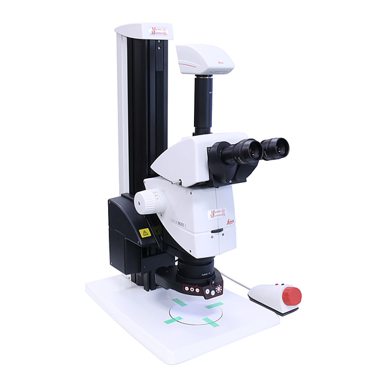
* Leica M205 C with 1.0× planapochromat and 10× eyepieces Leica M series Manual... -
Page 15: The Electronics: Comfort, Convenience And Safety
Never before have electronics been used as Reliability for your experiments diaphragm and more to the Leica LAS software. extensively in a Leica series as in the new Exact reproducibility of results is an increas- Thus you always know the conditions under M series. -
Page 16: The Modular Design: Everything Is Relative
The optics carriers, eyepieces, bases that cannot be met with standard parts, contact and more can be combined in any way you your Leica consultant. We have a solution for choose, allowing you to create the microscope every problem. -
Page 17: Maximum Compatibility
Maximum Compatibility Leica engineers were careful to ensure that the Tubes new M series—like its predecessors—remains The interface between the optics carrier and the compatible with existing series. This means tube has remained the same, so existing tubes that objectives, bases, tubes and so on can be fit the new M series. -
Page 18: On We Go
On We Go If your new Leica microscope has already been If, on the other hand, you are assembling the assembled and commissioned by your Leica microscope yourself, continue with the "Assem- consultant, click here to skip through the instal- bly"... -
Page 19: Assembly
Assembly Leica M series Manual... -
Page 20: Base And Focusing Column
1. Securely install the column adapter on the 2. Securely screw the focusing column to the column using the four included screws. base using the six included screws. Tools used ★ Hex socket screwdriver, 3 mm Leica M series Manual... -
Page 21: Optics Carrier
2. Press the optics carrier backwards to the ★ column so that the screw fit into the thread focusing column and screw it in place using provided and the lug fits into the groove. your other hand. Leica M series Manual... -
Page 22: Tube
Tools used positioning screw meshes with the guide position. No tools required. groove. ★ Preparations 1. Unscrew the positioning screw and remove the protective cover. Leica M series Manual... -
Page 23: Eyepieces
You can extend the overall magnification range 2. Remove the plastic tube guard. using available 10×, 16×, 25× and 40× wide- field eyepieces for persons wearing glasses. 4. Securely tighten the clamping screws. Leica M series Manual... -
Page 24: Objective
1. Remove the protective cap on the optics which is very heavy. Remove all specimens from on page 27. carrier by turning it. the stage plate first. 2. Screw the objective clockwise into the optics carrier. Leica M series Manual... -
Page 25: Objective Nosepiece - Assembly
1. Remove the transport anchor from the objective nosepiece. 3. Unscrew the three Phillips screws on the objective mount of the optics carrier and remove the intermediate ring. You can now adjust the parfocality (see instruc- tions on the next page). Leica M series Manual... -
Page 26: Objective Nosepiece - Adjusting Parfocality
5. Toggle to the 2× objective. Preparation 6. Select the strongest magnification and Open the iris diaphragm. refocus until the specimen appears abso- ★ lutely sharp. Set the dioptric correction of the eyepieces ★ to "0". Leica M series Manual... -
Page 27: Ax Carrier - Preparation
Before the AX carrier is installed, it may first switch in position. have to be prepared for the optics carrier to be used (Leica M125, M205 C or M165 C). 4. Important: push the switch all the way into 1. Check the switch position. -
Page 28: Ax Carrier - Assembly
1. Move the slide of the AX carrier into mid position. 3. Screw the objective to the AX carrier. 5. Install the optics carrier on the AX carrier. Wrong Right Leica M series Manual... -
Page 29: Transmitted-Light Base Tl St
4 Allen screws. installed. Make sure the devices are unpacked using the Allen key provided. on a flat, sufficiently dimensioned, and non-slip 3. Reattach the adapter plate to its original surface. position using the 6 Allen screws. Leica M series Manual... -
Page 30: Transmitted-Light Base Tl Bfdf: Before First Use
Removing the transport anchors • Before you can use the transmitted- light base for the first time, it is abso- lutely necessary to remove the two transport Anchor of mirror anchors as follows. Anchor of switching slide Leica M series Manual... -
Page 31: Transmitted-Light Base Tl Bfdf
3. Attach the stage to the base using the four Allen screws provided. Leica IsoPro™ manual cross-stage ★ ★ Leica IsoPro™ automatic cross-stage 4. Insert the glass plate back into the standard Standard stage 10 447 269 stage. -
Page 32: Tl Rc™ / Tl Rci
You can switch between the stage. stages at any time with just a few hand move- ments. The following paragraph assumes use of the base without the stage mounted. Disassembly is performed in reverse order of the following steps. Leica M series Manual... -
Page 33: Isopro™ Manual Cross-Stage: Assembly
1. Take the glass plate from the cross-stage. 2. Turn the cross-stage around and place it onto a non-slip surface. 3. Change the gear rod from the left to the right-hand side. 4. Skip the next two steps to mount the controls. Leica M series Manual... - Page 34 The fastener snaps into the part onto the transmitted-light base. cross-stage magnetically. 4. Attach the axis with the two Allen screws provided. 5. Attach the cover rail to the cross-stage. Leica M series Manual...
- Page 35 2. Attach your focusing drive column to the bottom using the three Allen screws. 5. Reinsert the glass plate back into the stan- dard stage. 3. Reattach the adapter plate to its original position using the three Allen screws. Leica M series Manual...
-
Page 36: Isopro™ Motorized Cross-Stage: Assembly
10 447 269), and the focusing drive will have to be mounted later. The motorized cross-stage is a sensitive preci- sion instrument. During installation, avoid subjecting the stage to impact or severe vibra- tions. Microscope base 3× M4 screws Motorized cross-stage Leica M series Manual... - Page 37 4. Remove the two M4 screws and the sleeve 5. Remove the four shock-absorbing cartons from the cross-stage. from the cross-stage. from the cross-stage. After removal, keep all the trans- port anchors in the plastic bag for future transport. Leica M series Manual...
- Page 38 3. Screw the cross-stage evenly onto the three threaded holes. 4. Push the cross-stage all the way back towards the column. 5. Reinsert the glass plate back into the stan- dard stage. Leica M series Manual...
- Page 39 2. Plug the CTL2 plug of the Leica PSC control- 4. Connect the PC and X-Y Stage DCI Module ler into another CTL2 interface. (with a suitable USB cable).
-
Page 40: Cables: Terminals
Cables: Terminals The new Leica M-series features extensive The Terminals The connection to the PC and to other instru- encoding with which various microscope data ments is made using the terminals on the rear and settings can be read out, transferred to the side of the column: PC and reproduced later. -
Page 41: Cables: Cable Duct
Tip: Estimate the length of the cable ends you 2. Remove the cover of the cable duct. will need before screwing on the cover. For thick cables, it is difficult to change the length retroactively. Leica M series Manual... -
Page 42: Cables: Diagram
Cables: Diagram Alternative installation Please use the Leica Application Suite to configure the functions LED5000 RL LED5000 MCI™ of the system. 115/230 V 115/230 V DCI Controlbox TL RCI™ PC USB Power/USB 115/230 V Footswitch 2... Footswitch 1 Smart Move Connector from Cross Stage (Connect to free CTL2-port on last footswitch.) -
Page 43: Leica Led5000 Mci
Leica LED5000 MCI™ The Leica LED5000 MCI™ (for "Multi Contrast Assembly 2. Connect the CAN-bus cable to either of the • Illumination") is installed using two screws. For 1. Hold the LED5000 MCI™ with one two sockets. (The flat part of the plug must... -
Page 44: Leica Led5000 Mci™: Alternative Assembly
For such purposes, the Leica LED5000 MCI™ is directly fastened to the column. Installation on the column 1. Pull the retaining stirrup out of the Leica LED5000 MCI™. Leica M series Manual... -
Page 45: Leica Led5000 Rl
Constraints objective as far as it will go and screw it the ring illuminator should be installed with The Leica LED5000 RL can be used in conjunc- into place. the cable facing backwards. However, it is also tion with the planapochromat 1× and planapo- possible to turn the ring illuminator sideways, chromat 0.63×... -
Page 46: Quick Start Guide
Quick Start Guide Leica M series Manual... -
Page 47: The Fastest Route To Success
The Fastest Route to Success Your Leica stereomicroscope has been delivered in completely assembled condition by your Leica partner, and naturally you want to get right to work. Therefore, your next step should be to study the Quick Start Guide, which outlines the most important steps at a glance. -
Page 48: Overview Of An M Series Microscope
Switch click stops on/off Coarse/fine focusing Fastening screw for the binocular tube (or accessories) Interchangeable objective Adjustable eyepiece tubes Eyepieces for spectacle wearers with dioptric correction and eyecups Fastening screws for the eyepieces Trinocular tube 10 Built-in iris diaphragm Leica M series Manual... -
Page 49: The Correct Interpupillary Distance
Not to worry—after a little while, it will become automatic. Reference value The distance between eye and eyepiece measures approx. 22 mm for 10/23B wide-field eyepieces for persons wearing glasses. ✓ ✗ Leica M series Manual... -
Page 50: Using The Eyepieces
2. If an eyepiece is equipped with the inte- great. Each eyepiece offers a certain magnification factor that has a determinative effect on the total magnification. Furthermore, all Leica eyepieces can be equipped with practical grati- cules that enable measuring and quantifying of specimens. -
Page 51: Focusing
The outer, fine adjustment is used for fine The coarse/fine adjustment carries a The focusing drive can be operated either focusing. load of up to 15 kg. ★ left- or right-handed. The resolution of the coarse/fine adjust- ★ ment is 1 µm. Leica M series Manual... -
Page 52: Adjusting The Resistance Of The Focus Drive
1. Grip the outer drive knobs with both hands and turn them towards each other until the desired resistance is reached during focus- ing. Leica M series Manual... -
Page 53: Changing The Magnification (Zoom)
1. Look into the eyepieces. covered: 2. Focus on the specimen. ★ Leica M125 = 16.5:1 Leica M165 C = 16.5:1 3. Rotate the magnification changer until the ★ Leica M205 C = 20.5:1 desired magnification is configured. ★ The rotary knob for the zoom can be used either left or right-handed. -
Page 54: Ratchet Steps And Magnification Levels
2. Push the bottom button upwards to enable of view diameters, with consideration given to enabled, photographs, measurement results the ratchet steps. the position of the magnification changer and etc. can be reproduced more accurately. the eyepiece and objective combination used. Leica M series Manual... -
Page 55: Parfocality: More Comfort And Convenience For Your Work
Parfocality: More Comfort and Convenience for Your Work All Leica stereomicroscopes are parfocally Parfocality matched, meaning that you can view a focused 1. Enlarge the view to the maximum level. specimen from the lowest to the highest magni- fication without having to refocus. There is no 2. -
Page 56: Iris Diaphragm
The and the depth of field increases. brighter, but the depth of field decreases. "depth of field" is the area of a specimen that is brought into sharp focus. Leica M series Manual... - Page 57 Eyepieces Leica M series Manual...
-
Page 58: Magnification Factors Of The Eyepieces
Dioptric correction Order number 10× ± 5 diopter settings 10 450 023 16× ± 5 diopter settings 10 450 024 25× ± 5 diopter settings 10 450 025 40× ± 5 diopter settings 10 450 026 Leica M series Manual... -
Page 59: Health Notes
The risk can be kept to a minimum by using individual eyepieces or detachable eyecups. Eyecups can be ordered separately. Please contact your Leica partner. Separate eyecups are an effective way of preventing infections. Leica M series Manual... -
Page 60: Dioptric Correction
Dioptric correction All Leica eyepieces are also available with Using the Dioptric Correction Note that when using dioptric correction, built-in dioptric correction, allowing the micro- 1. Set the dioptric correction of both eyepieces the advantage of parfocality is lost—thus scope to be used without glasses even by those to the mid position ("0"... -
Page 61: Dioptric Correction And Parfocality
Dioptric Correction and Parfocality Leica stereomicroscopes are parfocally matched. Adjusting 7. Look into the eyepieces. The prerequisite for this is the correct setting of 1. Set the dioptric correction for both the diopters and the parfocality. The following eyepieces to "0". -
Page 62: Graticules
Use with the AX carrier If possible, measure with the micro- scope carrier AX in vertical position. The measurements are more accurate without the convergence angle in the stereoscopic image. Leica M series Manual... - Page 63 Photography & Video Leica M series Manual...
-
Page 64: Photography & Video
For additional informa- online help. a new complete image. tion about Leica cameras, refer to the camera's documentation. Adapter If camera control using the Leica Application Suite is not required, conventional mirror reflex and rangefinder cameras from third-party manufacturers can be used. -
Page 65: Photo Tubes And C-Mounts
Cameras from third-party suppliers All Leica DFC cameras are equipped with a with a compatible C-mount adapter installed, it In addition to Leica DFC cameras with the stan- standardized C-mount interface. In turn, the can be corrected using the "Shading function"... -
Page 66: Trinocular Video/Phototube 50
50% is available for the two eyepieces. ★ 50% of the light is diverted to the video/ ★ photo beam path. Assembly Fasten the "trinocular tube 50%" to the optics carrier instead of the binocular observation tube (refer to page 22). Leica M series Manual... -
Page 67: Trinocular Video/Phototube 100
Assembly guide all available light into the camera. Fasten the "trinocular tube 100%" to the optics You can now photograph the specimen. carrier instead of the binocular observation tube (refer to page 22). Leica M series Manual... -
Page 68: Microscope Carrier
Microscope Carrier Leica M series Manual... -
Page 69: The Microscope Carrier Ax
Compatibility The planachromatic and planapochromatic objectives fit into the thread in the microscope carrier AX for the Leica M125, Leica 165 C and the Leica M205 C. 2. Push the microscope into the home posi- tion (mid position) to obtain a spatial view and tighten the clamping screw. - Page 70 Coaxial light and the Leica M205 C When using coaxial incident light together with 1. Unscrew the clamping screw. the Leica M205 C, unscrew the clamping screw and press the optics carrier towards the right 2. Push the microscope towards the left as (caution: the movement is only 2 mm).
-
Page 71: The Objective Nosepiece
Older Leica objectives can continue to be used, but without parfocality during the objective change. Leica M series Manual... -
Page 72: Objectives Andoptical Accessories
Objectives and optical accessories Leica M series Manual... -
Page 73: The Different Types Of Objectives
With planapochromatic objectives, the ★ finest structures are visible with high contrast. The sophisticated apochromatic correction allows these objectives to attain the highest color brilliance and fidelity. Leica M series Manual... -
Page 74: Leica M Series Manual
Bases Leica M series Manual... -
Page 75: Transmitted-Light Base Tl St: Controls
Rear side of the transmitted-light base TL ST Screws for changing the halogen lamp Power connection socket Adapter plate for easy assembly of focusing Power switch drives Removable glass plate Controller for light intensity Adjustment for deflection mirror Leica M series Manual... -
Page 76: Transmitted-Light Base Tl St: Operation
Inclined transmitted light Transmitted light that traverses the object obliquely will produce effects advantageous for observing semitransparent, opaque objects. Slowly pull the slider towards yourself until ★ the desired effect is achieved. Leica M series Manual... -
Page 77: Transmitted-Light Base Tl St: Lamp Replacement
2. Carefully pull out the lamp and mount by reduces the service life of the lamp! pulling them upwards. 3. Disconnect the lamp from the mount. 4. Insert the new lamp into the mount and reinsert the lamp holder. Leica M series Manual... -
Page 78: Transmitted-Light Base Tl Bfdf: Controls
Standard stage 10 447 269 Button to toggle between bright field and dark field Connector for cold light sources Button to toggle between bright field/ dark field (light conductor active f = 10 mm, end tube f = 13 mm) Leica M series Manual... -
Page 79: Transmitted-Light Base Tl Bfdf: Operation
"DF" ("dark field"). Transmitted-light control The TL BFDF transmitted-light base has a poten- tiometer that switches the light from "bright field" to "dark field". Fingertip with bright field illumination Identical subject with dark field illumination Leica M series Manual... -
Page 80: Tl Rc™ / Tl Rci™: Controls
2× CAN bus Standard stage 10 447 269 Screws for changing the halogen lamp Filter holder Control of top and bottom flaps of the Rottermann Contrast™ Button for mirror and horizontal movement of the mirror Transmitted-light base Leica M series Manual... -
Page 81: Tl Rci™: The Deflection Mirror
This means that the lower switch, rather tion and dark field-like illumination is possible. than of the upper switch, controls inverted relief contrast and vice-versa. Leica M series Manual... -
Page 82: Tl Rci™: Color Intensity And Temperature
The transmitted-light base TL RCI™ has two Using a USB mouse (only TL RCI™) electronic potentiometers that control the color The Leica USB mouse controls the CCIC™ and intensity (1) and color temperature (2). dimming function of the TL RCI™ base. Connect... -
Page 83: Tl Rc™ / Tl Rci™: Operation
The dynamic effect makes it easy to distinguish phase structures from amplitude structures. Switch for adjusting the inverted relief contrast Switch for adjusting the positive relief contrast Deflection mirror Leica M series Manual... -
Page 84: Tl Rci™: Methods In Transmitted Light
A dark field-like transmitted light is created. Outlines, fine edges and structures are bright, in contrast with the dark background, through diffraction of the light beams on the dark background. Leica M series Manual... -
Page 85: Tl Rci™: Relief Images
The effect can be strengthened or weakened by valleys. 2. Turn the deflection mirror into the notch gently tilting the deflection mirror. position at an angle of 45°. The effect can be strengthened or weakened by gently tilting the deflection mirror. Leica M series Manual... - Page 86 The dynamic effect makes it easy We recommend using the transmitted-light to distinguish phase structures from amplitude base with 1× or higher objectives, and not structures. objectives with a long focal length. Leica M series Manual...
-
Page 87: Using Filters
3. Insert the desired filter. ously. By customer request, the filters are also available as one-off items. 1. Switch off the light source or click (TL RCI™) the button for the shutter. 4. Switch the light source back on. Leica M series Manual... -
Page 88: Isopro™ (Non-Motorized): Controls
IsoPro™ (Non-motorized): Controls Operating the cross-stage IsoPro™ 1. To move the stage in X direction, rotate the outer knob. 2. To move the stage in Y direction, rotate the inner control ring. Leica M series Manual... -
Page 89: Isopro™ (Motorized): Controls
IsoPro™ (Motorized): Controls IsoPro X-Y Stage DCI module Leica PSC Controller Sub-D interface for Leica SmartMove™ Quick control/memory function 3 CTL2 interfaces Fine control in X direction USB interface (type B) Fine control in Y direction Motorized cross-stage Leica IsoPro ™... -
Page 90: System Illumination
System Illumination Leica M series Manual... -
Page 91: Leica Led5000 Mci
Leica LED5000 MCI™ Contact with the base • The Leica LED5000 MCI™ (for "Multi Contrast If the optics carriers are accidentally Illumination") is a universal high-output illu- lowered too far, contact between the minator. Three groups of 3 LEDs each can be base and MCI may result. - Page 92 The bottom row primarily provides contrast. The Leica LED5000 MCI™ can also be controlled by the LAS (Leica Application Suite) software. Maximum brightness Maximum contrast...
-
Page 93: Leica Led5000 Rl
10 increments. Touch either It is controlled using either the integrated or via of the two buttons to adjust the intensity in The Leica LED5000 RL has been designed for the Leica Application Suite (LAS). small increments. Hold a key to change the use with the 1.0×... - Page 94 Accessories Leica M series Manual...
-
Page 95: Leica Psc Controller
Connection Connect the Leica PSC controller and the Leica IsoPro™ motorized cross-stage. Fine control of the cross-stage The motorized Leica IsoPro™ cross-stage offers an accuracy of up to 0.25µm. To move to a posi- tion with maximum accuracy, use the left and right knobs on the joystick. -
Page 96: Dimensional Drawings
Dimensional Drawings Leica M series Manual... -
Page 97: Leica M125 / M165 C
Leica M125 / M165 C Leica M125 / M165 C with incident light base and new focusing column (dimensions in mm) Leica M series Manual... - Page 98 Leica M125 / M165 C (continued) Leica M125 / M165 C with transmitted-light base TL ST and manual focus (dimensions in mm) Leica M series Manual...
- Page 99 Leica M125 / M165 C (continued) Leica M125 / M165 C with transmitted-light stand TL RC™ and manual focus (dimensions in mm) Leica M series Manual...
- Page 100 Leica M125 / M165 C (continued) Leica M125 / M165 C with transmitted-light stand TL RC™, manual cross-stage Leica IsoPro™ and manual focus (dimensions in mm) max. 370 max. 370 X = +-75 mm Leica M series Manual...
-
Page 101: Leica M205 C
Leica M205 C Leica M205 C with transmitted-light stand TL ST and manual focusing drive (dimensions in mm) Leica M series Manual... - Page 102 Leica M205 C (continued) Leica M205 C with transmitted-light stand TL RCI™ and manual focusing drive (dimensions in mm) Leica M series Manual...
- Page 103 Leica M205 C (continued) Dimensions of Leica M205 C with transmitted-light stand TL RCI™, manual cross-stage Leica IsoPro™ and manual focus (dimensions in mm) max. 410 max. 410 X = +-75 mm Leica M series Manual...
-
Page 104: Leica Led5000 Mci
Leica LED5000 MCI Leica LED5000 MCI (dimensions in mm) 275.3 Leica M series Manual... -
Page 105: Leica Led5000 Rl
Leica LED5000 RL ø70 Leica M series Manual... -
Page 106: Specifications For The Bases
Specifications for the Bases Leica M series Manual... -
Page 107: Transmitted-Light Base Tl St
Relief Contrast System (RC™) CCIC (Constant Color Intensity Control) Internal shutter/lamp control Integrated filter holder Coated optics for increasing the color temperature Matching of high num. aperture Remote control options AntiShock™ Pads Dimensions (W×H×D) 340×430×85 mm Leica M series Manual... -
Page 108: Transmitted-Light Base Tl Bfdf
Coated optics for increasing the color temperature Matching of high num. aperture Yes** Remote control options Yes*** AntiShock™ Pads Dimensions (W×H×D) 340×390×90 mm *With cold light source Leica CLS150 LS **Concave mirror *** With external light source Leica M series Manual... -
Page 109: Tl Rc™ / Tl Rci
Matching of high num. aperture Yes*** Yes*** Remote control options Yes**** AntiShock™ Pads Dimensions of base (W×H×D) 340×390×95 mm 340×440×95 mm * Single-sided **With cold light source Leica CLS150 LS ***Concave mirror **** With external light source Leica M series Manual... -
Page 110: Isopro™ Motorized Xy Stage
IsoPro™ Motorized XY Stage Compatibility Leica incident light base and TL bases (TL BFDF, TL RC™, TL RCI™) Stage size (L × W × H) 335.5 mm × 370 mm × 41.5 mm Travel 152 mm × 102 mm (6" × 4") -
Page 111: Appendix
Appendix Leica M series Manual... -
Page 112: Calculating The Total Magnification And Field Of View Diameter
Calculation example: field of view diameter in the specimen MTOT VIS = MO × ME × z × q × r N FOV ∅ OF: M O × z ×q ×r 1 × 25 × 4 × 1.5 × 1.25 = 187.5× Leica M series Manual... -
Page 113: Care, Maintenance, Contact Persons
(Switzerland) AG, CH-9435 Heerbrugg. away from the instruments. decades, your Leica microscope will continue to work as well as on the very first day. Plugs, optical systems and mechanical parts ★... - Page 114 Keep accessories in a dust-free place when Remove dust with a pneumatic rubber bulb ★ ★ not in use. or with a soft brush. Clean objectives and eyepieces with special ★ optic cleaning cloths and with pure alco- hol. Leica M series Manual...
Need help?
Do you have a question about the M125 and is the answer not in the manual?
Questions and answers