Lincat Opus 700 User And Installation Instructions Manual
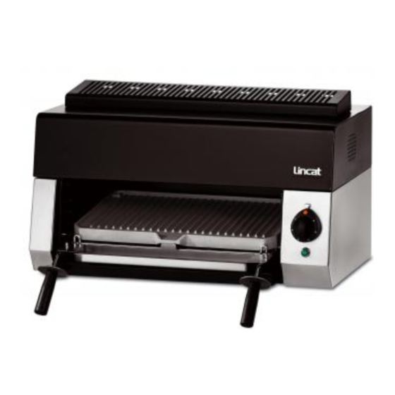
Electric salamander grill
Hide thumbs
Also See for Opus 700:
- Operating, and servicing instructions (23 pages) ,
- User, installation, servicing and conversion instructions (22 pages) ,
- User, installation and servicing instructions (16 pages)

Related Manuals for Lincat Opus 700


Summary of Contents for Lincat Opus 700
- Page 1 User and Installation Instructions Opus 700 Electric Salamander Grill OE7304 IS318 ECN3011...
- Page 2 USER / INSTALLATION INSTRUCTIONS Please read the following carefully before using this appliance. Warnings and Precautions This appliance must be installed by a competent installation engineer in accordance with the installation instructions, and should conform to the following requirements: • Health and Safety at Work Acts •...
-
Page 3: Section 1 - Technical Data
SECTION 1 – TECHNICAL DATA Salamander Grill Description OE7304 Product Code Overall height (mm) Width (mm) Depth, excluding grill shelf (mm) 525 x 265 (branding plate) Cooking Surface – w x d (mm) Weight (Kg) 560 x 285 x 200 Usable Grill Capacity –W x D x H (mm) 230VAC 1N~ and earth Electricity supply requirements... -
Page 4: Section 2 - Preparation For Use
SECTION 2 – PREPARATION FOR USE Figure 1 Remove all packaging material and protective coatings prior to installation. Control Panel On / Off Indicator Control Knob "Power On" Neon Figure 2 SITING The appliance must be installed in accordance with the appropriate regulations listed prior. The appliance should be installed on a level surface in a suitable position that is well lit, and positioned to minimise the possibility of accidental touching. -
Page 5: Section 4 - User Instructions
ELECTRICAL SUPPLY AND CONNECTION Connection of the electrical supply cable is made at the rear of the unit. Unclip the protective cover and fit a suitable cable into the strain relief and then to the inlet terminal block. The unit is supplied for connection to a single phase supply. - Page 6 Branding Plate Shelf-mounted Drip Tray Grill Shelf Figure 3 GRILL PAN An enamelled drip tray, or grill pan, is provided and sits in the base of the cooking cavity. This should always be in place when the grill is in use. CLEANING Ensure electricity supply is switched off before commencing cleaning.
-
Page 7: Section 5 - Component Replacement
SECTION 5 – COMPONENT REPLACEMENT HOOD 1. Remove the 2 screws on the underside of the front of the hood, at either side of the cooking cavity. 2. Release the 2 tabs by pulling them into the cavity. 3. Hinge back the hood to clear the inner flue and slide approximately 10mm to the right. 4. -
Page 8: Section 6 - Spare Parts List
SECTION 6 – SPARE PARTS LIST Part number Part description Used on BR11 Branding Plate OE7304 EL223 Element OE7304 EN10 Energy Regulator OE7304 RE28 Relay OE7304 HA05 Handle for SH13 OE7304 HA06 Handle Disc (Plastic) for SH13 OE7304 HA17 Handle Disc (Metal) for SH13 OE7304 KN233 Control Knob... - Page 9 ENSURE L1, L2 & L3 ARE LINKED ON TE45. THIS APPLIANCE IS SINGLE PHASE. NE39 GREEN NEON EN10 ENERGY REGULATOR TE45 TERMINAL EL223 RE28 2750W ELEMENT RELAY (2 off)
-
Page 10: Section 9 - Accessories
SECTION 9 - ACCESSORIES ACCESSORY INSTALLATION INSTRUCTIONS OA7907 Floor Stand • Position Salamander on top of floor stand, lining up the mounting holes in the frame with the pierce nuts in the base of the unit. • Fix in position using four M8 x 50mm long screws. •... -
Page 11: Section 10 - Service Information
Catering equipment should be routinely serviced to ensure a long and trouble free life. It is recommended that a competent qualified engineer service this appliance every 6 months. For help regarding the installation, maintenance and use of your LINCAT equipment, please call: - LINCAT SERVICE HELP DESK...
Need help?
Do you have a question about the Opus 700 and is the answer not in the manual?
Questions and answers