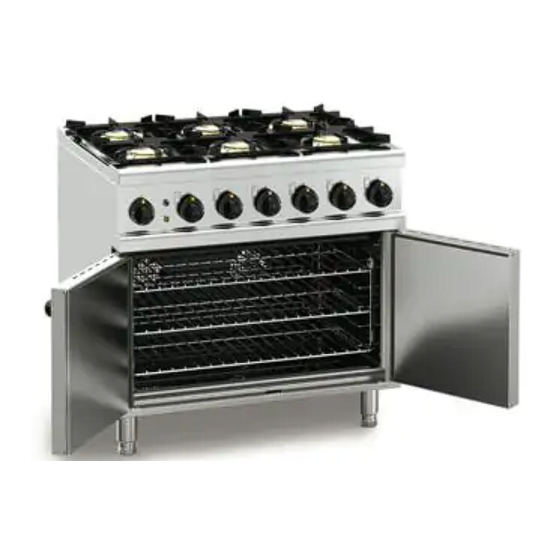
Lincat Opus OD7007 User, Installation, Servicing And Conversion Instructions
Dual fuel oven ranges
Hide thumbs
Also See for Opus OD7007:

Related Manuals for Lincat Opus OD7007


Summary of Contents for Lincat Opus OD7007
- Page 1 User, Installation, Servicing and Conversion Instructions Opus 700 Dual Fuel Oven Ranges OD7006 and OD7007 IS433 ECN3592...
-
Page 2: Customer Information
Used for the purposes for which it is intended, and with careful maintenance as outlined in this User Guide, your Lincat product will give you years of trouble free service. For use in GB & IE... -
Page 3: Table Of Contents
CONTENTS Contents Page Customer Information………………………………………………………. Warnings and Precautions………………………………………………… Technical Data……………………………………………………………….. Commissioning………………………………………………………………. Check List of Enclosures…………………………………………………... Installation…………………………………………………….……………… Conversion of Gas Types………………………………………………….. User…………………………………………………………………………….. 10-11 Servicing ……………………………………………………………………… Component Replacement ………………………………………….……… 12-14 Spare Parts List……………………………………………………………… Fault Finding…………………………………………………………………. Wiring Diagrams…………………………………………………………….. Service information………………………………………………………….. Guarantee………………………………………………………….………….. IS433 ECN3592... -
Page 4: Warnings And Precautions
WARNINGS AND PRECAUTIONS It is mandatory that all appliances are installed, commissioned and serviced by a qualified and competent person as defined by the regulations in force in the country of installation. Failure to comply will invalidate the warranty. WARNING! This appliance must be installed by a competent installation engineer in accordance with the installation instructions, and should conform to the following requirements: ... -
Page 5: Technical Data
TECHNICAL DATA Model OD7006 OD7007 Dimensions Overall Height (mm) Width (mm) Depth (mm) Weight (kg) Hob Cooking Surface w x d (mm) 600 x 600 900 x 600 Usable Oven Capacity w x d x h (mm) 500 x 540 x 400 715 x 540 x 400 Oven Shelf Size (mm) w x d 480 x 530... -
Page 6: Commissioning
Warranty Card User Instructions SERIAL NUMBER Each appliance manufactured at Lincat has a unique identifying number found in the top NOTE right hand corner of the data plate attached at the rear of the appliance. Please record that number in the space provided should it be required for future reference. -
Page 7: Installation
INSTALLATION SITING The installer must ensure that all regulations are met and that there is an unobstructed minimum distance of 1000mm from the top of the flue to the ceiling, which must be of non-combustible material. The appliance should be installed on a level surface ensuring the unit is stable and firmly located. Any partitions, walls or kitchen furniture in close proximity must be of non-combustible materials and not be closer than 50mm from the sides and rear of the flue. -
Page 8: Conversion Of Gas Types
CONVERSION OF GAS TYPES Conversion of Gas Type – Injector Changes Model Inlet Pressure Injector Mark Part No. 1.90 JE254 x 4 OD7006 20 mbar JE216 x 4 1.90 JE254 x 6 OD7007 20 mbar JE216 x 6 1.20 JE255 x 4 OD7006 37 mbar... - Page 9 Hob Valve Bypass Injectors Remove the bypass injectors C from each of the hob burner control valves B. Replace the bypass injectors applicable to the required gas type. Screw fully home but do not over tighten. Hob Tap Components Part Description Manifold...
-
Page 10: User
USER INSTRUCTION APPLIANCE USE This appliance is only for professional use and should only be used by qualified personnel. Ensure that the person responsible understands how to light, safely operate, clean and shut down the appliance and is made aware of the position and operation of the gas isolating cock in the event of an emergency. - Page 11 CLEANING Ensure the appliance is cool and the gas supply is isolated before commencing cleaning. After use wash the unit down with a warm detergent solution. Frequently check the burner cap ports for blockages. Clear as necessary. Do not use abrasives on stainless steel or enamelled parts. Do not use any products containing chlorine or hydrochloric acid to clean stainless steel surfaces.
-
Page 12: Servicing
SERVICING SERVICE ACCESS To access and service the gas control valves Remove the control knobs and fascia panel to gain access to the valves. Remove the two screws securing the valve boss and carefully withdraw the spindle from the valve. ... -
Page 13: Component Replacement
COMPONENT REPLACEMENT Access to Hob components can be more easily gained by removal of the the hob top (as shown below) rather than removing the fascia. HOB TOP ACCESS PANEL FASCIA FIXING SCREWS HOB TOP FASCIA FIXING SCREWS CONTROL KNOB HOOK HOB OVER FASCIA BEFORE FASTENING AT... - Page 14 Oven Fans Ensure that the gas supply to this unit is turned off and the electrical supply is disconnected. Remove the oven shelves. Loosen the fan guard screws and lift off the keyhole slots. Remove the hex head nut from the centre of the fan, this is a left-hand thread, and remove the fan blade.
-
Page 15: Spare Parts List
SPARE PARTS LIST Part Number Part Description Used On BU55 Door Bushes All models BU224 Burner Base All models BU225 Burner Injector Holder All models BU226 Burner Cap All models CO113 Copper Washer All models CA143 125mm Braked Swivel Castors All models CA145 125mm Un-Braked Swivel Castors... -
Page 16: Fault Finding
FAULT FINDING Burner/s will not light or stay lit Is there gas at the burner? Check injector for blockages Are thermocouple connections loose? Tighten connections Is the thermocouple voltage less than 15mV? Replace thermocouple Is the valve damaged? Replace valve Recheck system ... -
Page 17: Wiring Diagrams
OD7006 Wiring (E356) TE14 USE OUTER PAIRS OF TERMINALS ONLY NO CONNECTIONS TO INNER PAIR OF CONTACTS CO214 TH63 NE39 GREEN TH46 EL149 FA12 NE40 AMBER SW58 TO CHASSIS CONTROL PANEL COMPONENTS WIRES WITH A # TO BE STRIPPED 10mm NOT STD 6mm OD7007 Wiring (E329) I. -
Page 18: Service Information
Gas catering equipment should be routinely serviced to ensure a long trouble free life. It is recommended that this appliance is serviced every 6 months by a competent gas engineer. For help regarding the installation, maintenance and use of your LINCAT equipment, please call:- LINCAT SERVICE HELP DESK ...
Need help?
Do you have a question about the Opus OD7007 and is the answer not in the manual?
Questions and answers