Table of Contents
Advertisement
Quick Links
Download this manual
See also:
User Manual
Advertisement
Table of Contents

Related Manuals for Advantech EDG-4508+


Summary of Contents for Advantech EDG-4508+
-
Page 1: User Manual
EDG-4508+ 8-Port Ethernet to RS-232/422/485 Data Gateway EDG-4508R+ 8-Port Ethernet to RS-232/422/485 Data Gateway with Rear Wiring EDG-4516+ 16-Port Ethernet to RS-232/422/485 Data Gateway EDG-4516R+ 16-Port Ethernet to RS-232/422/485 Data Gateway with Rear Wiring User Manual... - Page 2 No part of this manual may be reproduced, copied, translated or transmitted in any form or by any means without the prior written permission of Advantech Co., Ltd. Information provided in this manual is intended to be accurate and reliable.
- Page 3 Product Warranty (2 years) Advantech warrants to you, the original purchaser, that each of its prod- ucts will be free from defects in materials and workmanship for two years from the date of purchase. This warranty does not apply to any products which have been repaired or...
- Page 4 Technical Support and Assistance Step 1. Visit the Advantech web site at www.advantech.com/support where you can find the latest information about the product. Step 2. Contact your distributor, sales representative, or Advantech's customer service center for technical support if you need addi- tional assistance.
-
Page 5: Table Of Contents
Contents Chapter 1 Overview ............2 Introduction ............... 2 Features ................2 Specifications ..............3 Packing Checklist.............. 3 Chapter 2 Getting Started ..........6 Figure 2.1:Installation Flow Chart ......... 6 Understanding EDG-4508(R)+ and EDG-4516(R)+ ..7 Connecting Hardware............8 Figure 2.2:EDG-4508+/4516+ Front Panels ....8 Figure 2.3:EDG-4508R+/4516R+ Front Panels .... - Page 6 Security Configuration ............ 33 Chapter 4 Port Mapping Utility........36 Overview ................. 36 Virtual COM Port Settings..........36 Inquiring Virtual COM Port Setting........ 39 4.3.1 Updating EDG Firmware ..........40 4.3.2 Self Test Function ............41 4.3.3 Save the Configuration ..........44 Chapter 5 Web-Based Configuration ......
- Page 7 Overview...
-
Page 8: Chapter 1 Overview
Chapter 1 Overview 1.1 Introduction This manual provides the necessary information to use EDG-4508(R)+ and EDG-4516(R)+. The Advantech Ethernet Data Gateway series (EDG series) consists of fast and cost-effective data gateways between RS-232/ 422/485 and Ethernet interfaces. EDG-4508(R)+ and EDG-4516(R)+ are part of the Ethernet Data Gate- way (EDG) family of multiple port modules. -
Page 9: Specifications
1.3 Specifications • I/O controller: 16C654 or compatible (auto hardware flow control) • LAN Speed: 100Base-TX (10/100 Mbps) • Ethernet Connection: RJ-45 • Serial: RS-232, RS-422 and RS-485 • Serial Connection: RJ-48 • DI/O: programmable 4DI,4DO for extra control • Signals: TxD, RxD, RTS, CTS, DTR, DSR, DCD, GND •... - Page 10 EDG-4508(R)+/4516(R)+ User Manual 4...
- Page 11 Getting Started...
-
Page 12: Chapter 2 Getting Started
Chapter 2 Getting Started Plug LAN Cable (RJ-45) to EDG-4508(R)+ /EDG-4516(R)+ Install Configuration Utility Troubleshooting to PC Search all EDG Series in Configuration Utility Complete all settings and IP addresses on PC Test connection by Ping IP address from PC Set up Serial port by Port Mapping Utility Connect cable (s) to serial... -
Page 13: Understanding Edg-4508(R)+ And Edg-4516(R)
2.1 Understanding EDG-4508(R)+ and EDG-4516(R)+ EDG-4508(R)+ and EDG-4516(R)+ are advanced Ethernet data gateway units. They extend traditional COM ports of a PC to Ethernet access. Through Ethernet networking, users can control and monitor remote serial devices and equipment over LAN or WAN. Since EDG-4508(R)+ and EDG-4516(R)+ are connected with the TCP/IP protocol, you will have to know fundamental facts about Ethernet net- working to get the server setup correctly. -
Page 14: Connecting Hardware
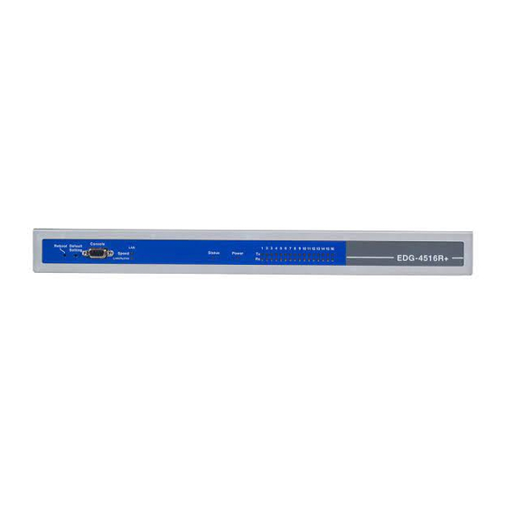
2.2 Connecting Hardware Figure 2.2: EDG-4508+/4516+ Front Panels Figure 2.3: EDG-4508R+/4516R+ Front Panels EDG-4508(R)+/4516(R)+ User Manual 8... -
Page 15: Figure 2.4:Edg-4508+/4516+ Led Indicators And Con Nectors
Figure 2.4: EDG-4508+/4516+ LED Indicators and Connectors Figure 2.5: EDG-4508R+/4516R+ LED Indicators Chapter 2... -
Page 16: Table 2.1:Edg-4508+/4516+ Led & Connector Defini Tions
Table 2.1: EDG-4508+/4516+ LED & Connector Definitions Item LED Status Description Power on Power off or no power Status Heart Beat Status Flash Monitoring Device Locate Function Steady Enable Dual Power Indicator Status (Optional) F Type Console connector Console for Console Configuration Ethernet RJ-45 Ethernet Connector Ethernet data being... -
Page 17: Figure 2.6:Edg-4508+/4516+ Rear Panel
DI/O PIN Connector Power Switch & Connector Fuse Storage Figure 2.6: EDG-4508+/4516+ Rear Panel Figure 2.7: EDG-4508R+/4516R+ Rear Panel Chapter 2... -
Page 18: Rack Mounting
2.2.1 Rack Mounting Figure 2.8: Rack Mounting EDG-4508(R)+/4516(R)+ User Manual 12... -
Page 19: Network Connection
2.2.2 Network Connection Figure 2.9: Ethernet Connector of EDG-4508+/4516+ Figure 2.10: Ethernet Connector of EDG-4508R+/4516R+ Chapter 2... -
Page 20: Power Supply Connection
2.2.3 Power Supply Connection Fuse Storage Figure 2.11: Power Switch and Connector with Fuse 2.2.4 Serial Port Connection Figure 2.12: 8 Ports RS-232/422/485 Serial Connector for EDG-4508+ Figure 2.13: 16 Ports RS-232/422/485 Serial Connector for EDG-4516+ Figure 2.14: RS-232/485/422 Serial Connectors for EDG-4508R+/4516R+ EDG-4508(R)+/4516(R)+ User Manual 14... -
Page 21: Ordering Information
2.2.5 Ordering Information • EDG-4508+ 8-port RS-232/422/485 to Ethernet Data Gateway with Front Wiring • EDG-4508R+ 8-port RS-232/422/485 to Ethernet Data Gateway with Rear Wiring • EDG-4516+ 16-port RS-232/422/485 to Ethernet Data Gateway with Front Wiring • EDG-4516R+ 16-port RS-232/422/485 to Ethernet Data Gateway with Rear Wiring •... -
Page 22: Installation
Ethernet card and the TCP/IP protocol installed. The following are the required steps for installing EDG- 4508(R)+ and EDG-4516(R)+. 1. Insert the Advantech industrial communication CD-ROM into the drive (e.g. D:\) on the host PC. Change the host computer's default drive from C: to D: 2. - Page 23 4. Carefully read the Software License Agreement, and press "Next" to continue. 5. The Setup program will specify a default installation path, C:\Program Files\Advantech\EDG COMPort Utility. Chapter 2...
- Page 24 If a new destination path is necessary, just click the Browse button to change the path. After you have specified the installation path, click the Next button. 6. In this step, you may select a specific program folder or just use the default setting and press "Next".
- Page 25 7. After setup has copied all program files to your computer, click the Finish button to finish the installation. Chapter 2...
- Page 26 EDG-4508(R)+/4516(R)+ User Manual 20...
- Page 27 Configuration...
-
Page 28: Chapter 3 Configuration
Start Menu as follows. Start Menu --> All Program --> Advantech --> EDG COMPort This EDG configuration utility will automatically search all the EDG devices on the network and show them on the left side of the utility. From here you can easily configure various parameters for TCP/IP configura- tion. - Page 29 You can click on the device name to show the features of the specific device. Click on the "+" before the model name (e.g. EDG-4516(R)+), and the utility will expand the tree structure to show the individual device name. For Example, EDG Configuration Utility shows "ADAM-00D0C968E17F"...
-
Page 30: Locating Edg-4508(R)+/4516(R)
3.2 Locating EDG-4508(R)+/4516(R)+ The configuration utility provides a "Locate" function to assist you in finding a specific device. You can select the EDG Series as a group or just select one specific module, e.g. EDG-4508+ or EDG-4516+. There are two different options for the Locate function (1) Designated: locates a specific device for you. -
Page 31: Device System Configuration
3.3 Device System Configuration Four functional categories Firmware Device Name Version Device List Device Description The configuration utility only searches for EDG-4508(R)+ and EDG- 4516(R)+ on the local network, and cannot search beyond a router or gateway. Make sure that the EDG-4508(R)+ or EDG-4516(R)+ you want to monitor resides in the same local network segment as the host PC. -
Page 32: Network Configuration
3.4 Network Configuration TCP/IP Option Ethernet Option Ethernet Option MAC Address This does not need configuration. Link Speed This function will show the current linking speed to be either 10Mbps or 100Mbps. However, the utility will auto-detect the current transmission speed on the network segment and set the transmission speed for the device accordingly. -
Page 33: Port Configuration
3.5 Port Configuration Port Setting Option Port Configuration Option Port Setting You can modify the description for individual port settings in the Port Setting Option. Name Show Port Name 8 Ports for EDG-4508(R)+ 16 Ports for EDG-4516(R)+ Description Show individual description for each port. You can change the description for your connected module to identify the connection from EDG Configuration Utility. - Page 34 Port Configuration You can modify port configuration in this Configuration Option such as Type, Parity, Flow Control, Data Bits, Stop Bits, Baud Rate and Host Idle Timeout. Type Serial Port Type You can change the connection type for your module to: RS-232, RS-422 or RS-485.
- Page 35 Parity Parity Check Type You can follow the parity check type of your connected module. The fol- lowing types are provided. • None • Odd • Even • Mark • Space Flow Control Flow Control Type You can choose the flow control type of your connected module. The fol- lowing types are available.
- Page 36 Data Bits Data Bits Type You can choose the number of Data Bits of your connected module to be 5, 6, 7 or 8. Stop Bits Stop Bits Type You can choose 1, 1.5 or 2 Stop Bits for your connected module EDG-4508(R)+/4516(R)+ User Manual 30...
- Page 37 Baud Rate Flow Control Type You can choose the Baud Rate of your connected module. The following rates are available: • 7,200 • 9,600 • 14,400 • 19,200 • 38,400 • 57,600 • 115,200 • 230,400 * Set All Port The ‘Set All Port’...
- Page 38 Host Idle Timeout The ‘Host Idle Timeout’ setting monitors the connection between the host and the device. If the ‘Host Idle Timeout’ setting time is reached, the device will release the resources allocated to the port mapping. This pre- vents a stalled host from affecting the connected device. . Note Host Idle Timeout and Auto Reconnection Function Detail...
-
Page 39: Security Configuration
3.6 Security Configuration For security reasons, you are highly recommended to use EDG’s security features. The EDG configuration utility provides security functions for the network structure. Only configure the allowed IP The system will auto detect the IP address for the currently connected computer. - Page 40 EDG-4508(R)+/4516(R)+ User Manual 34...
- Page 41 Port Mapping Utility...
-
Page 42: Chapter 4 Port Mapping Utility
Chapter 4 Port Mapping Utility 4.1 Overview The purpose of the port mapping utility is to help you manage all ports on one Windows 98/NT/2000/ME/XP platform. The utility displays three types of ports: used ports, unused ports and EDG ports. Please follow the Virtual COM port setting steps. - Page 43 2. Click the ADD button to assign a COM port to an EDG device. Module of Installed Device You can choose between all connected EDG devices. In this example, "EDG-4516+" was chosen. IP Address of Installed Device Enter the IP address you assigned in chapter 3.4. Port of Installed Device Choose the port where you want to setup: 8 ports for EDG-4508(R)+ and 16 ports for EDG-4516(R)+.
- Page 44 Memo You can add a description to the port setting if necessary. Click here to add a single port setting to your specification. Add All You can assign all ports to follow current settings by clicking the "Add All" button. This is more convenient than adding ports individually. For this example, we have selected COM21 and made all necessary settings for Port 1 of EDG-4516+.
-
Page 45: Inquiring Virtual Com Port Setting
Note If you assigned a different COM port to the same EDG series module port, the following dialog box will remind you. 4.3 Inquiring Virtual COM Port Setting You can check the virtual COM port setting by clicking on the EDG device’s ports. -
Page 46: Updating Edg Firmware
4.3.1 Updating EDG Firmware Updating Firmware Advantech continually upgrades its firmware. You can use the download function located on the Port Mapping utility to carry out the upgrade pro- cedure. Please access Advantech's web site at http://www.advantech.com to download the required computer file and then follow these instructions. -
Page 47: Self Test Function
4.3.2 Self Test Function Test The purpose of this test is to confirm that the communication from the host PC to the EDG device is OK. When the test is selected, an external test will be performed to check that the connection signal between each port is working properly. - Page 48 Signal Test • RTS->CTS: Checks the RTS and CTS signals between two ports. • DTR->RI: Checks the DTR and RI signals between two ports. • DTR->DSR: Checks the DTR and DSR signals between two ports. • DTR->DCD: Checks the DTR and DCD signals between two ports. Communication Parameters Test •...
- Page 49 Delete You can delete Port Mapping Setting by clicking the button. Apply If any changes are made, please press the button to confirm your modifications. Exit If you want to quit the utility, please click on the button. If any changes are made in the COM Port Mapping setting, the system reboot requirement will show up.
-
Page 50: Save The Configuration
4.3.3 Save the Configuration If you want to save or recover the configuration, you can select the "Import/Export" items. a. Select "File" b. Select "Import" or "Export". Save or open the configurations EDG-4508(R)+/4516(R)+ User Manual 44... - Page 51 Web-Based Configuration...
-
Page 52: Chapter 5 Web-Based Configuration
Chapter 5 Web-Based Configuration 5.1 Overview EDG devices can be configured through a web interface. By using a stan- dard web browser, the same procedure as with the Windows configura- tion utility can be used. In the browser’s address field, enter the IP Address of your EDG device. -
Page 53: Network Configuration
5.3 Network Configuration Under network configuration, there are: MAC address, IP Address, Sub- net Mask and Default Gateway. Enter the corresponding values for your network environment. Step 1. Enter IP Address, Subnet Mask and Default Gateway Step 2. Press ‘Save’ to store the settings. All new configurations will take effect after Note reset. -
Page 54: Port Configuration
5.4 Port Configuration Under port configuration, you can as sign the type and host idle timeout for individual ports. EDG-4508(R)+ and EDG-4516(R)+ support Note RS-232/ RS-422/RS-485.. Note The Host Time Out function is similar to the one in the Configuration Utility. EDG-4508(R)+/4516(R)+ User Manual 48... -
Page 55: Di/O Event Configuration
5.5 DI/O Event Configuration In event configuration, you can assign an DI event by enabling the check box and choosing the optimized action mode, Server IP and TCP Port for the active event. DI 0, DI 1, DI 2, DI 3 Options for Event 1 will be activated when any one of DI signal meets the Action option. -
Page 56: Reset Configuration
5.6 Reset Configuration All configurations will take effect after this reset step. Press the reset but- ton and the system will give a reset response. It will take a few seconds to reconnect with the new values. EDG-4508(R)+/4516(R)+ User Manual 50... - Page 57 Console Configuration...
-
Page 58: Chapter 6 Console Configuration
Chapter 6 Console Configuration 6.1 Overview The purpose of the Console Configuration is to help you manage your device in console mode. One of the main functions of the console mode is to change the web configuration login password. You can use terminal software like Hyper Terminal, Telix and other related terminal software. - Page 59 Step 3. Selecting a COM Port Confirm that the console configuration works ok. Step 4. COM Port Setting To connect the EDG series for console configuration, the port setting should match the EDG series' default setting. Console Configuration Default Setting Baud Rate: 57600 Data Bits: 8 Parity: None...
-
Page 60: Command List
Step 5. Connecting Successfully After connecting the device in console mode, you can simply type the "Help" command to show the Supported Command Lists 6.3 Command List Command Function version Displays the current firmware version Displays the log file date Displays or sets the date time Displays or sets the time... - Page 61 • log [Usage] log [Function] displays log file >log [05-09-2003 17:01:17] System up • date: displays or sets the date [Usage] date [Function] displays the date >date Current date is 05-09-2003 [Usage] date [mm-dd-yy [dse]] [Function] sets the date >date 06-09-03 >date >...
- Page 62 • net [Usage] net [Function] displays the configuration of net >net Current net is ip 172.18.3.226 gw 0.0.0.0 netmask 255.255.255.0 [Usage] net set ip d.d.d.d gw d.d.d.d netmask d.d.d.d [Function] sets the configuration of net >net set ip 172.18.3.227 gw 0.0.0.0 netmask 255.255.255.0 >net Current net is ip 172.18.3.227 gw 0.0.0.0 netmask 255.255.255.0 [USAGE] net save...
- Page 63 • port [USAGE] port [nn | all] [FUNCTION] displays the status of port(s) >port all The Port01 is type 422, idleto 30, idle The Port02 is type 232, idleto 30, idle The Port03 is type 232, idleto 30, idle The Port04 is type 232, idleto 30, idle The Port05 is type 232, idleto 30, idle The Port06 is type 232, idleto 30, idle The Port07 is type 232, idleto 30, idle...
- Page 64 • event [USAGE] event [nn | all] [FUNCTION] displays the configuration of event(s) [USAGE] event nn iomap xx action [L2H|H2L|CHG] server d.d.d.d:d [FUNCTION] sets the configuration of event [USAGE] event [nn | all] clear [FUNCTION] clears the configuration of event >event 2 iomap f action L2H server 172.18.3.58:503 >event 2 The Event2 is iomap f action L2H server 172.18.3.58:503...
- Page 65 • ping [USAGE] ping addr (addr: IP address of destination host) [FUNCTION] Sends ICMP ECHO_REQUEST packets to network hosts >ping 172.18.3.226 32 bytes from 172.18.3.226: icmp_seq=0 ttl=64 time=1 ms 32 bytes from 172.18.3.226: icmp_seq=1 ttl=64 time=1 ms 32 bytes from 172.18.3.226: icmp_seq=2 ttl=64 time=1 ms 32 bytes from 172.18.3.226: icmp_seq=3 ttl=64 time=1 ms •...
- Page 66 EDG-4508(R)+/4516(R)+ User Manual 60...
- Page 67 Event and DI/O Monitoring...
-
Page 68: Chapter 7 Event And Di/O Monitoring
Chapter 7 Event and DI/O Monitoring 7.1 Overview The purpose of Event and DIO Test is to help you monitor your EDG-4508(R)+/4516(R)+ DI/DO event(s). Follow these steps to test the DI/DO event(s). 7.2 Event and DI/O Monitoring 7.2.1 Polling Monitoring The following screen will appear once the EVENT Tester Program is executed. -
Page 69: Event Monitoring
7.2.2 Event Monitoring Once you have executed the steps in Chapter 3.4, you can use the tester to monitor the event status with the port and IP you have assigned before. Please follow these steps: Step 1. Assign IP and TCP Port for monitoring (Setting Event monitoring from Web Event Configuration) Step 2. -
Page 70: Di Value Inverse Option
Step 3. We can activate the DI0 event; tester will show the green indicator. Message Log will show event log with timer and event description. (DI0 Active and Event Monitor Shows Green) 7.2.3 DI Value Inverse Option Because of different wiring issues, we have provided DI value inverse optional function to Inverse DI value. - Page 71 Step 2. After enabling DI value inverse function, Green indicator means inactive and Red indicator means active. Step 3. After DI value inverse is enabled, follow the event configuration rule from the web configuration. Chapter 7...
-
Page 72: Programming I/O
O event handling environment. We provide a programmable I/O sample program for customer use. After installing the EDG COM Port Utility, the sample programs will be on the location as follow: C:\Program Files\Advantech\EDG COMPort Utility\samples\vc\ edgevtio. How to use the sample files? (1) The sample programs include following file and the develop envi- ronment is based on Microsoft Visual C++. - Page 73 memset(&HostAddr, 0, sizeof(SOCKADDR_IN)); HostAddr.sin_family = AF_INET; HostAddr.sin_addr.s_addr = INADDR_ANY; HostAddr.sin_port = htons(5000); +-->The TCP Port in the server application It remarks the function of htons(n), the parameter n means the TCP Port in server application and It helps the programmer to make his own program easier by referencing the note we provided.
- Page 74 mbtcp.h File name of mbtcp means Modbus TCP; we provide the easier definition of necessary parameter. For example, #define MODBUSTCPMAXMSGLENGTH #define MODBUSTCPMSGHDRLENGTH typedef struct __MODBUSTCPMSG { unsigned short wTransactionId; unsigned short wProtocolId; unsigned char byteMsgLenHigh; unsigned char byteMsgLenLow; unsigned char Data[2]; } TMODBUSTCPMSG;...
- Page 75 Troubleshooting...
-
Page 76: Chapter 8 Troubleshooting
This chapter explains how to solve some of the most common problems with the EDG Series. If you still have problems after reading this chapter, contact your dealer, or e-mail Advantech for help. "Configuration Utility can not find EDG Series"... - Page 77 "The host PC can access the EDG Series at this local site but later relocates the EDG Series to a remote site that PCs cannot access." Your IP address might have changed because of different network inter- face connections, and as a result, you are no longer on the EDG Series' Access Control list.
- Page 78 EDG-4508(R)+/4516(R)+ User Manual 72...
-
Page 80: Appendix A
Appendix A A.1 RS-232 Pin Assignment A.2 RJ-48 Cable PIN Assignment 2 3 4 5 6 7 8 9 2 3 4 5 6 7 8 9 EDG-4508(R)+/4516(R)+ User Manual 74... - Page 81 RS-422 Pin No. Description RS-485 Pin No. Description DATA- DATA+ Appendix A...
- Page 82 EDG-4508(R)+/4516(R)+ User Manual 76...
Need help?
Do you have a question about the EDG-4508+ and is the answer not in the manual?
Questions and answers