
Related Manuals for JAI CV-A50


Summary of Contents for JAI CV-A50
- Page 1 Industrial Monochrome CCD Camera CV-A50 / CV-A60 Operation Manual Camera: CV-A50 Revision B CV-A60 Revision A Manual: Version 2.1 A50Manualjul14.doc JPT 14-07-03...
-
Page 2: Table Of Contents
6.10. Other Functions...17 7. Configuring the Camera ... 18 7.1. RS-232C control..18 7.2. CV-A50/60 RS-232C command list...19 7.3. Camera Control Tool for CV-A50/60 ...20 7.4.1 HD/VD input-output selection ...21 7.4.2. Selecting termination of HD/VD input signals...21 8. Specifications ... 22 9. -
Page 3: General
1. General The difference from the previous manual is that the CCD sensor in CV-A50 is changed to new types. Now the used CCD sensors are: ICX-408AL-6, 409AL-6, 418ALL-6, 419ALL-6. The CV-A50/A60 is a range of monochrome CCIR and EIA interlaced 1/2” and 1/3” CCD cameras, designed for automated application, featuring an extremely small housing and a wide range of unique functions. -
Page 4: Camera Housing And Dimensions
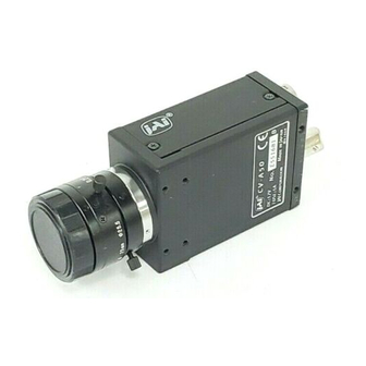
4. Camera Housing and Dimensions 12 pin Hirose connector for frame grabber interfacing and power (12V DC). BNC connector for video output. VS 1.0 Vpp 75 Ohm. 6 pin Hirose connector for trigger input and RS-232C control interface. Gain potentiometer for manual gain setting. Mounting holes, 8 x M3. -
Page 5: Pin Assignment
EEN will be low all the time in normal continous mode (TR=0), if the selected exposure time is longer than the video readout time. For schematic diagram of the input and output circuit with alternative settings refer to 5.3. CV-A50 / CV-A60 Pin configuration is compatible with EIAJ standard Pin no. -
Page 6: Input And Output Circuits
In the following schematic diagrams the input and output circuits for video and timing signals are shown. Jumper settings are shown as for factory default. For alternative connections refer to “10.1. CV-A50/60 emulating CV-M50 interfacing.” 5.3.1. Video output The video output is a 75 Ω DC coupled circuit. -
Page 7: Functions And Operations
6. Functions and Operations Apart from the standard continuous operation, the CV-A50/60 features three external asynchronous trigger modes (edge pre-select, pulse width controlled and start/stop) and a special frame-delay readout mode. Long integration time mode is also supported. 6.1. Basic functions Some of the primary camera functions need a general introduction before the operation modes are described. -
Page 8: Input-Output Of Hd/Vd Signals
6.2. Input-output of HD/VD Signals In the default setting the camera will accept external HD/VD signals on pin 6 and 7 of the 12 pin Hirose connector. If external HD/VD is applied, the camera will synchronize to it. If no external sync signals are applied, the camera will operate with its internal x-tal controlled sync. - Page 9 CV-A50 / CV-A60 Fig. 10. Horizontal timing details and pixel numbering for the CCD array. CCIR Fig. 11. Horizontal timing details and pixel numbering for the CCD array. EIA - 8 -...
- Page 10 CV-A50 / CV-A60 Fig. 12. Vertical timing details for interlaced. CCIR Fig. 12A. Vertical timing details for non-interlaced. CCIR - 9 -...
- Page 11 CV-A50 / CV-A60 Fig. 13. Vertical timing details for interlaced. EIA Fig. 13A. Vertical timing details for non-interlaced. EIA - 10 -...
-
Page 12: External Trigger Modes
6.4. External Trigger Modes This camera has 5 external asynchronous trigger modes, which can be set by RS-232C commands. Edge Pre-select Mode.TR=1 Pulse Width Control Mode. TR=2 Frame Delay read out mode. TR=3 Long Time Exposure Mode. TR=4 Start/stop Mode. TR=5 An external trigger pulse initiates the capture (input on pin 11 of the 12-pin Hirose connector or pin 5 of the 6-pin Hirose). -
Page 13: Edge Pre-Select Mode
6.5. Edge Pre-select Mode The leading edge of the trigger pulse initiates the exposure. The exposure time (accumulation time) is governed by the pre-defined shutter speed set by RS-232C. The resulting video is output as “odd field” for EIA and “even field” for CCIR, and appear 9H (EIA9 or 10H (CCIR) after the leading edge of WEN (polarity is user selectable). -
Page 14: Pulse Width Control Mode
6.6. Pulse Width Control Mode The leading edge of the trigger pulse initiates the exposure. The exposure time (accumulation time) is governed by duration of the trigger pulse. The resulting video is output as “odd field” for EIA and “even field” for CCIR, and appear 9H (EIA9 or 10H (CCIR) after the leading edge of WEN (polarity is user selectable). -
Page 15: Frame-Delay Read Out Mode
6.7. Frame-delay read out Mode This mode allows simultaneous capture of multiple camera using a common external trigger pulse subsequent multiplexed (sequential) readout using a single input frame grabber, as the user has control over when the image is read out from the CCD sensor. The exposure starts at the falling edge of the ext. -
Page 16: Long Time Exposure Mode
6.8. Long Time Exposure Mode The exposure time is the interval between 2 ext. VD pulses sent to the VD input of the camera (Pin No. 7 of the 12-pin Hirose connector). The exposure starts after input of the first ext. VD pulse, and ends after the next input of the next ext. -
Page 17: Start/Stop Mode
6.9. Start/Stop Mode The exposure time is controlled by the interval between the ext. trigger and the ext. VD signal. The exposure starts at the first HD pulse after the falling edge of the ext. trigger, and stops 14.5 H after the falling edge of the VD pulse. It means that the trigger pulse must be applied after the external VD pulse, for exposures less than 14.5 H. -
Page 18: Other Functions
Important notes on using this • As the start of exposure will be synchronized with the internal H signal, the start of exposure may be shifted by max 1H. • To avoid this shift (jitter), synchronize the camera with an external HD and make sure that the trigger pulse aligns to the HD signal as shown in Fig. -
Page 19: Configuring The Camera
All configuration of the A50/60 camera is done via the RS-232C port. The camera can be set up from a PC running terminal emulator software, or using JAI´s camera control software. Below is the description of the ASCII based short command protocol. -
Page 20: Cv-A50/60 Rs-232C Command List
7.2. CV-A50/60 RS-232C command list. Command Name A – General settings and useful commands Echo Back Camera Status request Online Help request Firmware version B – Timing and shutter related commands Scanning format Trigger mode Shutter mode Shutter speed Programmable expos. -
Page 21: Camera Control Tool For Cv-A50/60
CV-A50 / CV-A60 7.3. Camera Control Tool for CV-A50/60 From www.jai.com CV-A50/60 Camera Control Tool for Windows 98/NT/2000 can be downloaded. The control tool contents a camera control program and tools for making your own program. Below the different windows are shown. -
Page 22: Internal Switch And Jumper Settings
7.4. Internal Switch and Jumper Settings. 7.4.1 HD/VD input-output selection In the default setting the camera will accept external HD/VD signals on pins 6 and 7 of the 12 pin Hirose connector. The composite video signal from the camera will be synchronized to an external HD/VD source connected to the camera. -
Page 23: Specifications
8. Specifications Specifications Scanning system Frame rate (Full frame) Line frequency Pixel frequency CCD sensor 1/2”. CV-A50 *) CCD sensor 1/3”. CV-A60 Sensing area 1/2”. CV-A50 1/3”. CV-A60 Effective pixels Pixels in video output Cell size 1/2”. CV-A50 1/3”. CV-A60... -
Page 24: Spectral Sensitivity
10. Appendix 10.1. CV-A50 or CV-A60 emulating CV-M50 interfacing The CV-A50 and CV-A60 have a slightly different pin configuration on the 12-pin Hirose connector, compared to the M-series. This new configuration is compliant to the EIA-J standard. This means, however, that the CV-A50 and CV-A60 are not completely backward compatible with the CV-M50, CV-M300, etc in all cases (depending on the cable configuration). -
Page 25: Wen Out On Pin 6 On 6 Pin Connector
Configuration shown in Bold+Italic is factory default setting 10.3. CV-A50/60 without sync on video output. For applications where the video output signal should be without the composite sync signal, it is possible to remove the sync signal by removing an internal resistor. -
Page 26: Precautions
CV-A50 / CV-A60 10.4. Precautions Personnel not trained in dealing with similar electronic devices should not service this camera. The camera contains components sensitive to electrostatic discharge. The handling of these devices should follow the requirements of electrostatic sensitive components. -
Page 27: Users Record
Company and product names mentioned in this manual are trademarks or registered trademarks of their respective owners. JAI A-S cannot be held responsible for any technical or typographical errors and reserves the right to make changes to products and documentation without prior notification.
Need help?
Do you have a question about the CV-A50 and is the answer not in the manual?
Questions and answers