Table of Contents
Advertisement
Quick Links
Advertisement
Table of Contents

Related Manuals for Epson PhotoPC2100Z


Summary of Contents for Epson PhotoPC2100Z
- Page 1 SERVICE MANUAL Digital Still Camera EPSON PhotoPC 2100Z ® SEDC01002...
- Page 2 SEIKO EPSON CORPORATION. All efforts have been made to ensure the accuracy of the contents of this manual. However, should any errors be detected, SEIKO EPSON would greatly appreciate being informed of them.
- Page 3 REPAIRS ON EPSON PRODUCT SHOULD BE PERFORMED ONLY BY AN EPSON CERTIFIED REPAIR TECHNICIAN. MAKE CERTAIN THAT THE SOURCE VOLTAGES IS THE SAME AS THE RATED VOLTAGE, LISTED ON THE SERIAL NUMBER/RATING PLATE. IF THE EPSON PRODUCT HAS A PRIMARY AC RATING DIFFERENT FROM AVAILABLE POWER SOURCE, DO NOT CONNECT IT TO THE POWER SOURCE.
-
Page 4: About This Manual
Provides preventive maintenance procedures and the lists of P O I N T condition that is necessary to accomplish a task efficiently. It may Epson-approved lubricants and adhesives required for servicing also provide additional information that is related to a specific the product. - Page 5 Revision Status Revision Date of Issue Description October 15, 2001 First release November 12,2001 "Optics" on page -6: Revise the specification. "Shooting Mode" on page -7 : Revise the specification. "Shooting Operation" on page -10 : Revise the specification. "Playback Mode Functions" on page -11 : Revise the specification. "Beep Sound Specifications"...
- Page 6 November 30,2001 "LCD (Brightness) Adjustment" on page -65 : Add the CAUTION and revise the adjustment procedure. "USB ID Writing" on page -71 : Error correction. February 20,2002 "Adjustment Programs" on page -61: Revise the CAUTION. "Installation" on page -64 : Revise the procedure. "BC (Battery Check) Compensation Value Writing"...
-
Page 7: Table Of Contents
Chapter 1 Product Description 1.3.18.4 Processing for Number 999 Folder ..........24 1.3.18.5 Others ....................24 1.1 Features ....................... 4 1.4 Interface Specifications ..................25 1.2 Exterior View ...................... 5 1.4.1 USB Interface .................... 25 1.2.1 Dimensions and Weight ................5 1.4.2 AC Adapter Input .................. - Page 8 Chapter 3 Troubleshooting 5.3.7 USB ID Writing ..................71 3.1 Troubleshooting ....................44 Chapter 6 Maintenance Chapter 4 Disassembly and Assembly 6.1 Overview ......................73 6.1.1 Check Items before Shipment ..............73 4.1 Overview ......................47 4.1.1 Precautions ....................47 Chapter 7 Appendix 4.1.2 Tools ......................
-
Page 9: Chapter 1 Product Description
C H A P T E R PRODUCT DESCRIPTION... -
Page 10: Features
User interfaces Shooting is possible immediately after opening the lens barrier. Major features of EPSON PhotoPC 2100Z are as follows: Function display is more easy to understand, thanks to use of icon animation. Access FDA format (Function Direct Assign) as GUI operations, which has a Advanced appearance high evaluation of user-friendliness. -
Page 11: Exterior View
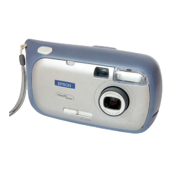
PhotoPC 2100Z Revision B 1.2 Exterior View 1.2.1 Dimensions and Weight Dimensions 130 mm × 73 mm × 46.7 mm (not including some protrusions) Weight 265 g (without any of the batteries, strap and memory card) Tripod mount Compliant with JIS B7103 1/4 Appearance Figure 1-1. -
Page 12: Functional Specifications
PhotoPC 2100Z Revision B 1.3 Functional Specifications 1.3.2 Optics 1.3.1 Image Data 1/2.6 inch color area CCD, interlace reading, complementary color filter Total pixels: 2,300,000 pixels (1901 x 1212) Recording format Effective pixels: 2,180,000 pixels (1806 x 1206) JPEG compression: DCF (Exif ) format Lens Thumbnail image... -
Page 13: Shooting Mode
PhotoPC 2100Z Revision B 1.3.3 Shooting Mode Table 1-1. Flash Auto 1.3.3.1 Shooting Functions ISO140 ISO110 ISO110 ~ 200 Display of information zone (Flash Firing) The following information is displayed in the “information zone” during shooting Wide LV8.3 or above LV8.3 or below mode. - Page 14 Sequential numbering of files +1.5EV offset The highest EPSON folder number and file number in the DCIM Folder in the CF card Shutter speed: It is possible for exposure can +1.5EV. When it is dark r are stored in memory.
- Page 15 PhotoPC 2100Z Revision B Digital zoom Smooth digital zoom for a maximum of 2.5 magnification can be used. 9-stage switching Processing is slow during digital zoom operation. Shift to VRF shooting mode during digital zoom on, digital zoom function is removed.
-
Page 16: Shooting Operation
PhotoPC 2100Z Revision B 1.3.3.2 Shooting Operation Table 1-6. Shooting Process Operation (continued) User/Camera Contents of Camera Target Pressing the shutter button halfway (focus lock) Operation Operation Processing Time Evaluates AF/AE/AWB, and reflects the evaluated value in the preview Pressing the display. -
Page 17: Playback Mode Functions
EPSON's cameras. 95% framing display is performed, but only with an aspect ratio of 3:2 only. Table 1-7. Processing (Operation) for Images Taken by Other EPSON's Cameras One-by-one image playback (forward/backward) PhotoPC 800 Images are displayed one by one by switching. Images are scrolled by means of the W/... -
Page 18: Setup Mode Functions
PhotoPC 2100Z Revision B 1.3.5 Setup Mode Functions 1.3.5.1 Beep Sound Specifications The following three types of sounds are used: Display of information zone A: 4.9KHz Displays the following information in the “information zone” while in setup mode. B: 1.2KHz Date / cursor / battery status C: 2.4KHz Date and time setting... -
Page 19: Communication With Pc
PhotoPC 2100Z Revision B Table 1-8. Beep Sound Specifications (continued) 1.3.6 Communication with PC Sound Type of communication Item Pattern Mode Status Sound Patterns Only USB communication (Mass Storage Class) is available. Name Serial communication is not supported. Shooting Self-timer button AC (repeats until shutter starts Start of communication... -
Page 20: Memory
PhotoPC 2100Z Revision B 1.3.7 Memory 1.3.8 Built-in Clock Built-in RAM Built-in clock 8MB (64Mb (32 bits × 2M)) The camera incorporates a clock. Default is January 1, 2001, 0:00. Does not count down earlier than this time. Built-in ROM Capable of counting up to December 31, 2035, 23:59. -
Page 21: Miscellaneous (Abnormal Operation)
When the batteries (or AC adapter) are removed during operation and re-inserted LCD monitor Playback mode is set by pressing the playback button irrespective of the EPSON 1.6 type D-TFD color LCD monitor previous operation. 55,000 pixels: 237 x 234 pixels... -
Page 22: Led Indications
PhotoPC 2100Z Revision B 1.3.11.2 LED Indications *2: Duty flashing has off time longer than on time. 0.5Hz: on for 0.1 second and off for 1.9 second. Table 1-9. LED Indications Camera LED INDICATIONS FOR CF FULL TO ITS CAPACITY (NO CF INSERTED) Detailed Status Remarks Status... -
Page 23: Shooting Status Display On Color Lcd
PhotoPC 2100Z Revision B 1.3.11.3 Shooting Status Display on Color LCD LED INDICATION FOR ERROR STATUS The color LCD monitor displays color frames for different functions. This function is In an error status, the red LED is lit and beep sound A (4.9KHz) is emitted for three available only for LCD shooting. -
Page 24: Switches And Buttons
PhotoPC 2100Z Revision B 1.3.12 Switches and Buttons 1.3.12.2 Locations of Switches and Buttons The figures below show the names and locations of switches and buttons. 1.3.12.1 Switches and Buttons The table below shows a list of switches and buttons. Shutter Button Table 1-13. -
Page 25: Lens Extending And Retracting Control
PhotoPC 2100Z Revision B 1.3.13 Lens Extending and Retracting Control Lens extending and retracting are controlled by the opening/closing operation of the lens cover. Setting the Lens Cover Switch to “Open” position: Opens the lens cover and extends the lens. Setting the Lens Cover Switch to “Close”... -
Page 26: Storage In The Camera
PhotoPC 2100Z Revision B : Stored, ×: Default, ∆: Conditional 1.3.14 Storage in the Camera 1.3.14.1 Shooting The table below indicates the conditions under which the camera stores the parameters in shooting mode. Table 1-14. Storage System in Shooting Mode Mode Switching Viewfinder ↔... -
Page 27: Playback / Dpof
PhotoPC 2100Z Revision B : Stored, ×: Default, ∆: Conditional 1.3.15 Playback / DPOF The table below indicates the conditions under which the camera stores the parameters in playback mode. Table 1-15. Storage System in Playback Mode Mode Switching After Power Saving Mode Playback Button Item... -
Page 28: Setup
PhotoPC 2100Z Revision B : Stored, ×: Default ∆: Conditional 1.3.15.1 SETUP The table below indicates the conditions under which the camera stores the parameters in SETUP mode. Table 1-16. Storage System in SETUP Mode Mode Switching Backup Battery Runs Power Saving Mode 2 Lens Cover Closed After Communication... -
Page 29: Processing Time
1440) About 10 images Note: *1: The number of shots is based on EPSON's measurement conditions. *2: Each number indicated above is the average number of shots when no data has been stored in the memory. If other files have been stored in the memory, the number of shots permitted decreases depending on the remaining capacity. -
Page 30: Sequential Numbering Of Files
1.3.18.3 Defining the Highest File Number in CF Card If the folder of the highest number in the card is an EPSON folder, the highest file number in that holder is defined as the highest file number in the memory card. -
Page 31: Interface Specifications
PhotoPC 2100Z Revision B 1.4 Interface Specifications 1.4.2 AC Adapter Input Polarity: Center-plus USB connector For exclusive use with the AC adapter EU-40 (7.0V 2A) The exclusive USB cable must be used. AC adapter input 1.4.3 CompactFlash DC input terminal for AC adapter (7.0V) EIAJ RC-5320 type 3 (compatible with EU- CompactFlash interface CompactFlash Card Type1 is supported. -
Page 32: Exclusive Communication Cable
(Old method) / 200 and more images (New method) Viewfinder shooting 1000 images or more Playback 210 minutes The battery life depends on measurement conditions. The measurement method is provided by EPSON. The conditions are followings; Product Description Interface Specifications... -
Page 33: Power Saving Specifications
PhotoPC 2100Z Revision B 1.4.7 Power Saving Specifications LCD SHOOTING This section provides the power saving specifications for PhotoPC 2100Z. Old method 1.4.7.1 Shooting Mode BATTERY Power saving mode 1 (The camera enters this mode after 2 minutes of no operation) New method Power saving mode 1 is entered after displaying icon animation. -
Page 34: Playback Mode
PhotoPC 2100Z Revision B Power saving mode 2 (The camera enters this mode from power saving mode 1 1.4.7.2 Playback Mode after 30 seconds of no operation) BATTERY Restoration condition: The camera is restored to the normal status by one of the following events: Power saving mode 1 (The camera enters this mode after 2 minutes of no operation) -
Page 35: Communicate Mode
PhotoPC 2100Z Revision B Complete off (Power is turned off from the power saving mode 2 after 2 minutes 1.4.7.4 SETUP Mode of no operation) BATTERY Table 1-24. Camera Status Power saving mode 1 (The camera enters this mode after 2 minutes of no Power Saving Power Saving Complete... - Page 36 PhotoPC 2100Z Revision B Complete off (Power is turned off from the power saving mode 2 after 2 minutes of no operation) Table 1-26. Camera Status Power Saving Power Saving Complete Default Mode 1 Mode 2 LCD Monitor Lens Note: *1: The orange LED flashes (Duty is changed). *2: Startup time is longer than in the viewfinder mode (because of CPU shutdown).
-
Page 37: Accessories
PhotoPC 2100Z Revision B 1.5 Accessories AA alkali battery x 4 CF memory card 8MB Hand strap Instruction manuals (CR-ROM) USB cable (Exclusive use with PhotoPC 2100Z) CD-ROM install guide Bundle software (EU, Asia only) Photo Suite 3SE (Win) Photo Suite 3 (Mac) Photo Vista Full Version (Win/Mac) Product Description Accessories... -
Page 38: Option
PhotoPC 2100Z Revision B 1.6 Option AC ADAPTER NI-MH BATTERY CHARGER Model name: Model name: EU-40 (same as that for PhotoPC 3000Z) EU-38 (same as that for PhotoPC 800) Model number: Model number: B867081, B867131, B867091, B867101, B867121, B867101, B867111, B867151, B818171-0200, B818181-0100, B818173-0100, B818174-0200, B818175-0200, B867171 B818178-0200, B818177-0200, B818182-0000... -
Page 39: Environmental Conditions
1.7.2 Power Supply Specifications DC input voltage (AC adapter) Average: 7.0 VDC Maximum: The AC adapter (EU-40) made by Epson must be used. Maximum DC input voltage Maximum: The AC adapter (EU-40) made by Epson must be used. 1.7.3 Intended Location of Use... -
Page 40: Safety Standards & Reliability
PhotoPC 2100Z Revision B 1.8 Safety Standards & Reliability 1.8.1 EMI and Safety Standards Table 1-27. EMI and Safety Standards Market EMI and Safety Standards FCC part15 subpart B class B Canada CSA C108.8 class B Europe EMC Directive 89 / 336 / EEC (CE Marking) EN55022 Class B EN61000-3-2 (When AC adapter is used) EN61000-3-3 (When AC adapter is used) -
Page 41: Prohibitions And Precautions
PhotoPC 2100Z Revision B 1.9 Prohibitions and Precautions Never see the sun through the viewfinder. Never use any AC adapter other than the specified one. Never use any batteries other than the specified ones. Remove the batteries when the camera is not to be used for a long time. Do not insert or eject the CF card when power is on. -
Page 42: Chapter 2 Operating Principles
C H A P T E R OPERATING PRINCIPLES... -
Page 43: Overview
PhotoPC 2100Z Revision A 2.1 Overview This chapter explains operating principles of PhotoPC 2100Z. 2.1.1 Circuit The circuit block diagram of PhotoPC 2100Z is shown on the next page. Operating Principles Overview... - Page 44 PhotoPC 2100Z Revision A Operating Principles Overview...
-
Page 45: Operating Principles Of Control Circuit
Records taken pictures. Converts the image formed on the CCD by the lens into an electrical signal. LCD Controller EPSON EM1811D 1/2.6 inches, 2,310,000 pixels, complementary color filter, Based on the video signal generated by the main CPU, the LCD interline transfer controller generates various signals which are necessary to drive the LCD. -
Page 46: Operating Principles Of Power Supply Circuit
PhotoPC 2100Z Revision A Table 2-2. Peripheral Elements of 8-bit CPU (continued) 2.1.3 Operating Principles of Power Supply Circuit Major Element / Unit Functions 2.1.3.1 Power Supply Voltages Focusing Motor Incorporated in the lens barrel to drive the lens for focusing. Power supplies to PhotoPC 2100Z are as listed below. - Page 47 PhotoPC 2100Z Revision A [PS_block7019e.pdf] Operating Principles Overview...
-
Page 48: Operating Principles Of Power Supply Circuit
PhotoPC 2100Z Revision A 2.1.3.2 Operating Principles of Power Supply Circuit 2.1.4 Operating Principles of Flash Circuit The control IC (IC1) in the power supply circuit has a 2-channel control system. One The major functions of the flash circuit are to charge the flash capacitor at the flash channel is used for voltage down by L81 to generate 3.3 V. - Page 49 C H A P T E R TROUBLESHOOTING...
-
Page 50: Troubleshooting
PhotoPC 2100Z Revision A 3.1 Troubleshooting Table 3-1. Troubleshooting (continued) Problem Possible Cause Checking and Remedy This section describes how to identify the defective unit or parts from observed Taken pictures Shorted CCD power supply Replace Main Circuit Board. problems. are completely Faulty operation of shutter Check initial operation of shutter... - Page 51 PhotoPC 2100Z Revision A Table 3-1. Troubleshooting (continued) Problem Possible Cause Checking and Remedy Power does not Main CPU does not operate, so that Replace Main Circuit Board. turn on, with the 8-bit CPU has displayed an error. camera beeping Flash memory firmware has Replace Main Circuit Board.
-
Page 52: Chapter 4 Disassembly And Assembly
C H A P T E R DISASSEMBLY AND ASSEMBLY... -
Page 53: Overview
PhotoPC 2100Z Revision B 4.1 Overview This section describes procedures for disassembling the main components of the Remove the batteries and plug off the AC adapter before W A R N I N G product. disassembling the camera. Always wear gloves for disassembly and reassembly to avoid Unless otherwise specified, disassembled units or components can be reassembled by injury from sharp metal edges. -
Page 54: Tools
Attached at the end of this manual, A2 size RS-232C interface EPSON 1091792 RS-232C cable EPSON 1091790 Serial cable (serial 17-pin-DIN 7-pin) EPSON 1104424 Stabilized DC power supply Note: “ ”:available on the market, “EPSON”: available from EPSON Disassembly and Assembly Overview... -
Page 55: Screws
PhotoPC 2100Z Revision B 4.1.3 Screws 4.2 Disassembly Table below shows the screws used with PhotoPC 2100Z. The flowchart below shows step-by-step disassembly procedure for PhotoPC 2100Z. Table 4-2. Screws When disassembling each component, refer to the page number shown in the figure below. -
Page 56: Housing Disassembly
PhotoPC 2100Z Revision B 4.2.1 Housing Disassembly Hooks 4.2.1.1 Rear Cover Removal Remove the one screw (THB1.7x5.5) and the four screws (THB1.7x4.0) securing the CN1104 Rear Cover. THB1.7x4.0 THB1.7x5.5 THB1.7x4.0 Figure 4-3. Rear Cover Removal THB1.7x4.0 Disconnect the FFC of the Rear Cover from the connector CN1104 on the Main Circuit Board. -
Page 57: Front Cover Removal
PhotoPC 2100Z Revision B 4.2.1.2 Front Cover Removal W A R N I N G When the Rear Cover has been removed, the terminals of the capacitor C3108 for flash firing appears at the upper left corner of Remove the Rear Cover. (See "Rear Cover Removal" on page 50) the camera. -
Page 58: Front Cover Disassembly
PhotoPC 2100Z Revision B 4.2.1.3 Front Cover Disassembly 4.2.2 Disassembly of Circuit Boards Disengage the seven hooks fastening the Face Plate to the Front Cover. 4.2.2.1 Release Circuit Board Removal Remove the housing. (See "Housing Disassembly" on page 50) Disconnect the FFC of the Release Circuit Board from the connector CN1103 on the Main Circuit Board. -
Page 59: Power Supply Circuit Board Removal
PhotoPC 2100Z Revision B 4.2.2.2 Power Supply Circuit Board Removal 4.2.2.3 Monitor LCD Removal Remove the housing. (See "Housing Disassembly" on page 50) Remove the housing. (See "Housing Disassembly" on page 50) Remove the one screw (THB1.7x2.5) and the one screw (SPB1.7x4.0) securing the Remove the Power Supply Circuit Board. -
Page 60: Flash Circuit Board Removal
PhotoPC 2100Z Revision B Disengage the two hooks fastening the bottom end of the Fixing Frame to the Main 4.2.2.4 Flash Circuit Board Removal Circuit Board, and disengage the upper hook of the LCD from the Main Circuit Board. Remove the housing. (See "Housing Disassembly" on page 50) While lifting the Monitor LCD, disconnect the FFC from the connectors CN1105 and Remove the Power Supply Circuit Board. - Page 61 PhotoPC 2100Z Revision B C H E C K When installing the Flash Circuit Board, make sure that the When soldering the Flash Tube lead wires, take care not to C A U T I O N P O I N T circuit board is installed in the groove in the battery box.
-
Page 62: Battery Box Removal
PhotoPC 2100Z Revision B 4.2.2.5 Battery Box Removal Remove the one screw (THB1.7x4.0) securing the Main Circuit Board and Battery Box. Remove the housing. (See "Housing Disassembly" on page 50) NOTE: Tightening torque for the screw THB1.7x4.0: 0.12N⋅m Remove the Power Supply Circuit Board. (See "Power Supply Circuit Board Removal" on page 53) Remove the Flash Circuit Board. -
Page 63: Lens Assy (Lens & Ccd Unit) Removal
PhotoPC 2100Z Revision B 4.2.2.6 Lens Assy (Lens & CCD Unit) Removal PCB Fixing Frame Hook of Battery Box Remove the housing. (See "Housing Disassembly" on page 50) Remove the Power Supply Circuit Board. (See "Power Supply Circuit Board Removal" on page 53) Remove the Flash Circuit Board. - Page 64 PhotoPC 2100Z Revision B NOTE: Tightening torque for the screw SPB 1.7x2.5: 0.12N⋅m CCD terminals SPB1.7x2.5 Do not remove the two black screws of the Lens Assy, which C A U T I O N connect the CCD and the lens barrel to each other. If you remove them, dust or other foreign matters could adhere to the CCD.
-
Page 65: Chapter 5 Adjustment
C H A P T E R ADJUSTMENT... -
Page 66: Overview
PhotoPC 2100Z Revision E 5.1 Overview This section describes the adjustments required according to service components once The table below shows the adjustments required when components have been replaced. they have been replaced and also describes procedures for such adjustments. Table 5-1. -
Page 67: Tools
PhotoPC 2100Z Revision E 5.2 Tools The PC to be used must be of a model which permits use of the C A U T I O N USB interface on Windows 98 or a later operating system. 5.2.1 Tools Only one program file must be stored in one CF card if the file The table below lists the tools needed for adjustments of PhotoPC 2100Z. -
Page 68: Explanation Of Error Codes
PhotoPC 2100Z Revision E Without firmware installation, the adjustment by CF 5.2.3 Explanation of Error Codes C A U T I O N card has the counter that control to adjustment count on If any error occurs during execution of these adjustment programs, the LCD monitor of each adjustment item. -
Page 69: Adjustment
PhotoPC 2100Z Revision E 6: AF adjustment error 5.3 Adjustment Corrective action Check the conditions under which the adjustment is performed. Perform the 5.3.1 Installation of firmware adjustment again and if a similar error recurs, replace the Lens Assy (with CCD) with a new one. -
Page 70: Installation
PhotoPC 2100Z Revision E 5.3.2 BC (Battery Check) Compensation Value Writing Playback Button Print Button This adjustment is executed in order to input the threshold values for battery check into flash memory on the Main Circuit Board. This adjustment includes the initialization of the adjusted value storage area in the camera. -
Page 71: Lcd (Brightness) Adjustment
PhotoPC 2100Z Revision E Insert into the camera the CF card in which the BC compensation program has been 5.3.3 LCD (Brightness) Adjustment installed. Adjust the brightness on the monitor to optimize the contrast of display on the monitor. Hold down the F Button and Shutter Button together and press the Playback Button, Adjusted values are written in flash memory on the Main Circuit Board. - Page 72 PhotoPC 2100Z Revision E With the PC having two or more serial ports, use COM1 port, if C A U T I O N possible. When c the camera to PC by the RS-232c interface, connect the following figure. Do not misconnect the cables, otherwise the RS-232C interface board may have damage.
-
Page 73: Ccd Gain Adjustment, Shutter Compensation Black Defect Writing And White Defect Compensation
PhotoPC 2100Z Revision E 5.3.4 CCD Gain Adjustment, Shutter Compensation Pressing the shutter button fully will turn off power to the camera. Black Defect Writing and White defect Remove the CF card from the camera. compensation 10. Close the lens cover of the camera. The adjustments to be made here are CCD gain adjustment, shutter compensation and 11. -
Page 74: Strobo Adjustment
PhotoPC 2100Z Revision E 5.3.5 Strobo Adjustment This process adjusts the amount of flash light with the lens positioned on the WIDE (wide-angle) side and TELE (telescopic) side. Adjusted values are written in flash memory on the Main Circuit Board. For this adjustment, use of a dark box or dark room is desirable. -
Page 75: Af (Auto Focus) Compensation
PhotoPC 2100Z Revision E 5.3.6 AF (Auto Focus) Compensation In this adjustment, the adjusted values for AF in-focus positions are written into flash Do not move the camera during adjustment. C A U T I O N memory on the Main Circuit Board. 70 cm AF Adjustment Chart Figure 5-7. - Page 76 PhotoPC 2100Z Revision E Press the Shutter Button fully to turn off power to the camera. Remove the CF card from the camera. If a printed chart is to be used, make sure that the pattern of C A U T I O N the chart is not incomplete, soiled or blur.
-
Page 77: Usb Id Writing
PhotoPC 2100Z Revision E 5.3.7 USB ID Writing In this adjustment, the USB ID is written in flash memory on the Main Circuit Board. If the display shows “A camera number can't be inputted” during C A U T I O N When the Main Circuit Board has been replaced with a new one, the camera can not USB ID writing, it signifies that the USB ID is not written use the USB ID which is stored on the old circuit board. -
Page 78: Chapter 6 Maintenance
C H A P T E R MAINTENANCE... -
Page 79: Overview
PhotoPC 2100Z Revision B 6.1 Overview Table 6-2. Check Items before Shipment PhotoPC 2100Z requires no specific maintenance (lubrication / adhesion / cleaning). Check Item OK/NG Camera should be cleaned according to its necessity, however, such as for dust What is firmware version? Ver. incoming at the repairing service or fingerprint. -
Page 80: Chapter 7 Appendix
C H A P T E R APPENDIX... -
Page 81: Circuit Board Connection Diagram
PhotoPC 2100Z Revision A 7.1 Circuit Board Connection Diagram The next page shows the circuit board connection diagram. Appendix Circuit Board Connection Diagram... -
Page 83: Circuit Board Component Layout
PhotoPC 2100Z Revision A 7.2 Circuit Board Component Layout This section shows the circuit board component layouts for PhotoPC 2100Z. Figure 7-1. Main Circuit Board 1 Appendix Circuit Board Component Layout... - Page 84 PhotoPC 2100Z Revision A Figure 7-2. Main Circuit Board 2 Appendix Circuit Board Component Layout...
- Page 85 PhotoPC 2100Z Revision A Figure 7-4. Release Circuit Board (Solder Side) Figure 7-3. Release Circuit Board (Components Side) Appendix Circuit Board Component Layout...
- Page 86 PhotoPC 2100Z Revision A Figure 7-6. Flash Circuit Board 2 Figure 7-5. Flash Circuit Board 1 Appendix Circuit Board Component Layout...
-
Page 89: Circuit Diagrams
PhotoPC 2100Z Revision A 7.3 Circuit Diagrams This section shows the following circuit diagrams for PhotoPC 3100Z. Circuit Diagram of Main Circuit Board 1-8 Circuit Diagram of Release Circuit Board Circuit Diagram of Flash Circuit Board Circuit Diagram of Power Supply Circuit Board Appendix Circuit Diagrams... -
Page 101: Exploded Diagrams
PhotoPC 2100Z Revision A 7.4 Exploded Diagrams This section shows exploded diagrams. The parts to which no reference number is assigned will not be available as after-sale service parts. FOR CP-80Z/PHOTO PC2100Z NO.1 Rev.01 B150 Appendix Exploded Diagrams... - Page 102 PhotoPC 2100Z Revision A The parts to which no reference number is assigned will not be available as after-sale service parts. FOR CP-80Z/PHOTO PC2100Z NO.2 Rev.01 B150 Appendix Exploded Diagrams...
- Page 103 PhotoPC 2100Z Revision A The parts to which no reference number is assigned will not be available as after-sale service parts. FOR CP-80Z/PHOTO PC2100Z NO.3 Rev.01 B150 Appendix Exploded Diagrams...
- Page 104 PhotoPC 2100Z Revision A The parts to which no reference number is assigned will not be available as after-sale service parts. FOR CP-80Z/PHOTO PC2100Z NO.4 Rev.01 B150 Appendix Exploded Diagrams...
- Page 105 PhotoPC 2100Z Revision A The parts to which no reference number is assigned will not be available as after-sale service parts. FOR CP-80Z/PHOTO PC2100Z NO.5 Rev.01 B150 Appendix Exploded Diagrams...
-
Page 106: Asp List
PhotoPC 2100Z Revision A 7.4.1 ASP List Table 7-1. ASP List Ref. No. Sales Part Code The Ref. Nos. correspond to the numbers shown in the exploded diagrams. LENS ASSY. RETAINER PCB Table 7-1. ASP List RETAINER MONITOR Ref. No. Sales Part Code SCREW SP BOLT 1.7X2-3X0.6 FRONT COVER ASSY. -
Page 107: Af Adjustment Chart
PhotoPC 2100Z Revision A 7.5 AF Adjustment Chart The AF adjustment chart is shown on the next page. For use, output the chart with the A2 size. (See "AF (Auto Focus) Compensation" on page 69) Appendix AF Adjustment Chart...
Need help?
Do you have a question about the PhotoPC2100Z and is the answer not in the manual?
Questions and answers