Allied Telesis AT-FS705L Installation Manual
Fast ethernet switch
Hide thumbs
Also See for AT-FS705L:
- Datasheet (2 pages) ,
- Datasheet (2 pages) ,
- Installation manual (35 pages)
Table of Contents
Advertisement
Advertisement
Table of Contents

Related Manuals for Allied Telesis AT-FS705L


Summary of Contents for Allied Telesis AT-FS705L
-
Page 1: Installation Guide
AT-FS705L Fast Ethernet Switch Installation Guide PN 613-50326-00 Rev C... - Page 2 Allied Telesyn, Inc. reserves the right to make changes in specifications and other information contained in this document without prior written notice. The information provided herein is subject to change without notice. In no event shall Allied Telesyn, Inc. be liable for any incidental, special, indirect, or consequential damages whatsoever, including but not limited to lost profits, arising out of or related to this manual or the information contained herein, even if Allied Telesyn, Inc.
-
Page 3: Electrical Safety And Emission Compliance Statements
Electrical Safety and Emission Compliance Statements Standards: This product meets the following standards: U.S. Federal Communications Commission Declaration Of Conformity Manufacture Name: Allied Telesyn, Inc. Manufacture Address: 960 Stewart Drive, Suite B Sunnyvale, CA 94085 USA Manufacture Telephone: 408-730-0950 Declares that the product:... - Page 4 Electrical Safety and Emission Compliance Statements RFI Emission EN55022 Class B Immunity EN55024 Electrical Safety EN60950 (TUV), UL60950 ( Important: Appendix B contains translated safety statements for installing this equipment. When you see the , go to Appendix B for the translated safety statement in your language.
-
Page 5: Table Of Contents
Table of Contents Electrical Safety and Emission Compliance Statements .....iii Welcome to Allied Telesyn ................vii Where to Find Web-based Guides ..............vii Documentation Conventions ................vii Contacting Allied Teleysn Technical Support..........viii Online Support ..................viii Telephone Support ...................viii E-mail Support ..................viii Returning Products ................... - Page 6 Chapter 2 Installation ....................... 9 Verifying the Package Contents ................ 9 Planning the Installation ................. 10 Selecting a Site ..................10 Reviewing Safety Guidelines ..............11 Installing the Switch on a Desktop..............12 Wall-Mounting the Switch ................13 Warranty Registration ..................13 Chapter 3 Troubleshooting ....................
-
Page 7: Welcome To Allied Telesyn
AT-FS705L Fast Ethernet Switch. Where to Find Web-based Guides The Allied Telesyn web site at www.alliedtelesyn.com offers you an easy way to access the most recent documentation, software, and technical information for all of our products. For product guides, select “Support &... -
Page 8: Contacting Allied Teleysn Technical Support
You can use the Knowledge Base to submit questions to our technical support staff and review answers to previously asked questions. Telephone Support For technical support by phone, contact Allied Telesyn at one of the following locations: Americas Germany... -
Page 9: Returning Products
Authorization (RMA) number. A product sent to Allied Telesyn without a RMA number will be returned to the sender at the sender’s expense. To obtain an RMA number contact Allied Telesyn’s Technical Support at one of the following locations: North America... -
Page 10: Tell Us What You Think
Tell Us What You Think If you have any comments or suggestions on how we might improve this or other Allied Telesyn documents, please fill out the General Enquiry Form online. This form can be accessed by selecting “Contact Us” from... -
Page 11: Chapter 1 Overview
Chapter 1 Overview The AT-FS705L is an unmanaged Layer 2 switch. This switch can be used in a variety of network configurations and topologies. You can use the switch to create small workgroups with dedicated 10 Mbps and 100 Mbps links to your network devices, such as workstations, servers, printers, and routers. -
Page 12: Features
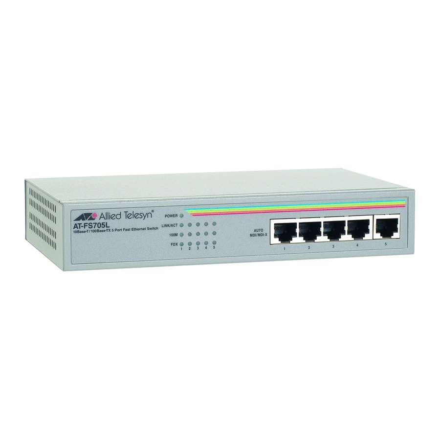
Overview Features LEDs for unit and port status Auto MDI/MDI-X on the twisted pair ports Half- or full-duplex operation on both ports Five RJ-45 twisted pair connectors Store and forward switching mode MAC address table with a capacity of 2,000 addresses Small compact size for use on a desktop or wall-mountable Status LEDs Table 1 defines the LEDs for the switch. -
Page 13: Twisted Pair Ports
The twisted pair ports on the AT-FS705L switch can operate in either half- duplex or full-duplex mode. The switch sets the duplex mode automatically through auto-negotiation. -
Page 14: Auto Mdi/Mdi-X
MDI to MDI, you would use a crossover cable. The AT-FS705L switch features automatic MDI/MDI-X. The RJ-45 port automatically determines the configurations of the port on the device to which it is connected and then configures itself appropriately. For example, if a port on a switch is connected to a port on a bridge, which is typically wired as MDI, the port on the switch automatically configures itself as MDI-X. -
Page 15: Store And Forward
The MAC address table in the AT-FS705L switch can store up to 2,000 MAC addresses. To prevent the table from becoming filled with addresses of end- nodes that are no longer active, the switch has a MAC address aging timer. -
Page 16: Network Topologies
Overview Network Topologies The AT-FS705L switch can be used in three different topologies: standalone, cascade, and uplink. Each topology is describe below. Standalone A standalone topology uses one switch to connect the end-nodes. Figure 2 illustrates a standalone topology that uses an AT-FS705L switch to connect several workstations and a server. -
Page 17: Cascade
AT-FS705L Switch Installation Guide Cascade Figure 3 illustrates two AT-FS705L switches connected together to support multiple network segments. This is commonly referred to as ‘cascading.’ Figure 3 Cascading Topology... -
Page 18: Uplink
Overview Uplink Figure 4 illustrates multiple AT-FS705L switches can be interconnected using uplinks from a centralized backbone Fast Ethernet switch. Sales Department Engineering Department Finance Department Fast Ethernet Switch IS Department SNMP Station 100 Mbps 10 Mbps 10 Mbps Figure 4 Uplink Topology... -
Page 19: Chapter 2 Installation
Chapter 2 Installation This chapter contains the installation instructions for the AT-FS705L switch. This switch can be used on a desktop or mounted on a wall. Verifying the Package Contents Make sure the following items are included in your package. If any item is missing or damaged, contact your Allied Telesyn sales representative for assistance. -
Page 20: Planning The Installation
Installation Planning the Installation Be sure to observe the following guidelines when planning the installation of your switch. The end-nodes connected to the twisted pair ports can operate at 10 Mbps or 100 Mbps and half or full-duplex. The switch uses auto- negotiation to determine the correct speed and duplex mode for each port. -
Page 21: Reviewing Safety Guidelines
AT-FS705L Switch Installation Guide Reviewing Safety Guidelines Please review the following safety guidelines before installing the AT-FS705L switch. Warning Electrical Shock Hazard: To prevent electrical shock, do not remove the cover. There are no user-serviceable parts inside. The unit contains hazardous voltages and should only be opened by a trained and qualified technician. -
Page 22: Installing The Switch On A Desktop
Installation Installing the Switch on a Desktop The AT-FS705L switch can be used on a desktop or mounted on a wall. To wall-mount the switch, refer to “Wall-Mounting the Switch” on page 13. To install an AT-FS705L switch on a desktop, perform the following... -
Page 23: Wall-Mounting The Switch
AT-FS705L Switch Installation Guide Wall-Mounting the Switch The switch can be mounted horizontally on a wall using the keyholes on the bottom of the switch. The screws, plastic anchors, and other materials necessary to mount the switch on a wall are not provided. -
Page 25: Chapter 3 Troubleshooting
Chapter 3 Troubleshooting Follow the guidelines below to test and troubleshoot the installation in the event a problem occurs. If the POWER LED is OFF, do the following; Make sure that the power cord is securely connected to the wall outlet and the power connector is securely connected to the back of the switch. - Page 26 Troubleshooting If there is a communication problem between the end-nodes connected to the switch, do the following: Verify that the end-nodes are operating with the same duplex mode. If you are still experiencing problems after testing and troubleshooting the installation, refer to “Contacting Allied Teleysn Technical Support” on page viii or visit our web site at www.alliedtelesyn.com for support information.
-
Page 27: Technical Specifications
Appendix A Technical Specifications Physical Dimensions: W x D x H 197 mm x 117 mm x 37 mm (7.75 in x 4.59 in x 1.45 in) Weight: 0.610 kg (1.35 lbs) Environmental Maximum Operating: 0° to 40° C (32° to 104° F) Maximum Storage: -20°... -
Page 28: Agency Compliance
Technical Specifications Agency Compliance EMI/RFI: FCC Class B, EN55022 Class B Electrical Safety: , TUV Immunity: EN55024 Pinout Assignments Figure 6 shows the pinout assignments for the RJ-45 connector. Pin 8 Pin 1 Figure 6 RJ-45 Pin Assignments Table 3 lists the 10Base-T/100Base-TX connector pins and their signals when the port is operating in either MDI or MDI-X configuration. -
Page 29: Translated Safety And Emission Information
Appendix B Translated Safety and Emission Information Important: This appendix contains multiple-language translations for the safety statements in this guide. Wichtig: Dieser Anhang enthält Übersetzungen der in diesem Handbuch enthaltenen Sicherheitshinweise in mehreren Sprachen. Vigtigt: Dette tillæg indeholder oversættelser i flere sprog af sikkerhedsadvarslerne i denne håndbog. - Page 30 Translated Safety and Emission Information Standards: This product meets the following standards. U.S. Federal Communications Commission Declaration Of Conformity Manufacture Name: Allied Telesyn, Inc. Manufacture Address: 960 Stewart Drive, Suite B Sunnyvale, CA 94085 USA Manufacture Telephone: 408-730-0950 Declares that the product:...
- Page 31 AT-FS705L Switch Installation Guide Safety Electrical Notices Warning: Electric Shock Hazard To prevent electric shock, do not remove the cover. No user-serviceable parts inside. This unit contains hazardous voltages and should only be opened by a trained and qualified technician. To avoid the possibility of electric shock, disconnect electric power to the product before connecting or disconnecting the LAN cables.
- Page 32 Translated Safety and Emission Information Automatische Spannungseinstellung Dieses Gerät stellt sich automatisch auf die auf dem Etikett aufgeführten Spannungswerte ein Vorsicht: Das netzkabel dient zum trennen der stromversorgung. Zur trennung vom netz, kabel aus der steckdose ziehen. Geräte Der Klasse 1 Diese Geräte Müssen Geerdet Sein. Der Netzstecker darf nur mit einer vorschriftsmäßig geerdeten Steckdose verbunden werden.
- Page 33 AT-FS705L Switch Installation Guide Betjeningstemperatur: Dette apparat er konstrueret til en omgivende temperatur på maksimum 40 grader C. Alle Lande: Installation af produktet skal ske i overensstemmelse med lokal og national lovgivning for elektriske installationer. Eisen: Dit product voldoet aan de volgende eisen.
- Page 34 Translated Safety and Emission Information Normes: ce produit est conforme aux normes de suivantes: Emission d’interférences radioélectriques EN55022 Classe B Immunité EN55024 Sécurité électrique EN60950 (TUV), UL60950 ( Sécurité Information Sur Les Risques Électriques Avertissement: Danger D’électrocution Pour éviter toute électrocution, ne pas ôter le revêtement protecteur du matériel.
- Page 35 AT-FS705L Switch Installation Guide Standardit: Tämä tuote on seuraavien standardien mukainen. Radioaaltojen häirintä EN55022 Luokka B Kestävyys EN55024 Sähköturvallisuus EN60950 (TUV), UL60950 ( Turvallisuus Sähköön Liittyviä Huomautuksia Varoitus: Sähköiskuvaara Estääksesi sähköiskun älä poista kantta. Sisällä ei ole käyttäjän huollettavissa olevia osia. Tämä laite sisältää vaarallisia jännitteitä ja sen voi avata vain koulutettu ja pätevä...
- Page 36 Translated Safety and Emission Information Standard: Questo prodotto è conforme ai seguenti standard. Emissione RFI (interferenza di radiofrequenza) EN55022 Classe B Immunità EN55024 Sicurezza elettrica EN60950 (TUV), UL60950 ( Norme Di Sicurezza Avvertenze Elettriche Attenzione: Pericolo Di Scosse Elettriche Per evitare scosse elettriche non asportare il coperchio. Le componenti interne non sono riparabili dall’utente.
- Page 37 AT-FS705L Switch Installation Guide Sikkerhetsnormer: Dette produktet tilfredsstiller følgende sikkerhetsnormer. RFI stråling EN55022 Klasse B Immunitet EN55024 Elektrisk sikkerhet EN60950 (TUV), UL60950 ( Sikkerhet Elektrisitet Advarsel: Fare For Elektrisk Sjokk For å unngå elektrisk sjokk, må dekslet ikke tas av. Det finnes ingen deler som brukeren kan reparere på...
- Page 38 Translated Safety and Emission Information Padrões: Este produto atende aos seguintes padrões. Emissão de interferência de radiofrequência EN55022 Classe B Imunidade EN55024 Segurança Eléctrica EN60950 (TUV), UL60950 ( Segurança Avisos Sobre Características Elétricas Atenção: Perigo De Choque Elétrico Para evitar choque elétrico, não retire a tampa. Não contém peças que possam ser consertadas pelo usuário.
- Page 39 AT-FS705L Switch Installation Guide Estándares: Este producto cumple con los siguientes estándares. Emisión RFI EN55022 Clase B EN55024 Inmunidad Seguridad eléctrica EN60950 (TUV), UL60950 ( Seguridad Avisos Electricos Advertencia: Peligro de electrochoque Para evitar un electrochoque, no quite la tapa. No hay ningún componente en el interior al cual puede prestar servicio el usuario.
- Page 40 Translated Safety and Emission Information Standarder: Denna produkt uppfyller följande standarder. Radiostörning EN55022 Klass B Immunitet EN55024 EN60950 (TUV), UL60950 ( Elsäkerhet Säkerhet Tillkännagivanden Beträffande Elektricitetsrisk: Risk för elektrisk stöt För att undvika elektrisk stöt, ta ej av locket. Det finns inga delar inuti som behöver underhållas.
Need help?
Do you have a question about the AT-FS705L and is the answer not in the manual?
Questions and answers